PSB560 Installation Instructions
Open the original PDF document
View PDF[t] 800.413.8783 805.494.0622 E-mail: service@sdcsecurity.com 801 Avenida Acaso, Camarillo, CA 93012 PO Box 3670, Camarillo, CA 93011
INSTALLATION INSTRUCTIONS
PSB560 PRESSURE SENSE BAR
The PSB560 is a pressure sense bar designed to release any magnetic lock with minimal applied pressure and requires no prior knowledge or effort for free egress. The available standard lengths fit standard door openings of 36". 42" and 48" (with stops no greater than 5/8") without cutting.
- 1. Using a level, mark a horizontal center line at the standard 40" to 42" from the finished floor.
- With the template provided, mark all mounting holes and the wire hole by placing the template on the face of the door against the door jamb with door in the closed position as illustrated in Figure A.
- 3. Using a 3/8" drill bit, drill four (4) mounting holes through the door and the one (1) wire mounting hole in the hinge side of the door.
- 4. Install the sexbolts provided from the outside of the door.
- 5. Install the bar mounting bracket to the latch side of the door using the 1/4-20 screws provided.
- 6. Insert the bar rail under the tab of the installed latch side bracket.
- 7. Position the bar against the door and install the second bar mounting bracket using the 1/4-20 mounting screws provided. Make sure the bar rail is located under the bracket's mounting tab.
- NOTE: If bar length needs be cut, install both mounting brackets on the door and measure between upright tabs on bracket for proper length of bar.
- 9. Pull wire cable through the door's wire transfer (see Figure B for wiring connections).
FINAL ASSEMBLY AND TESTING
- 1. Turn on the power.
- 2. Depress the bar and verify proper orientation. The sensitivity is factory set and should not need adjustment under normal conditions.
- 3. Install the end caps with the #8-32 screws provided.
Armored Power Transfer SDC PSB560
SENSITIVITY ADJUSTMENT
Sensor Bar may be installed without sensor adjustments. Calibration is not required. If a higher activation pressure setting is desired to inhibit tampering from the outside, the sensors may be adjusted from 5 lbs. through 15 lbs. without removing the bar from the door.
- 1. Open the door.
- 2. Remove the latch side end cap.
- 3. Slide the touch bar to one side.
- 4. Adjust the pot on the electronics modules to the desired sensitivity.
-
5. Slide the bar back into position and test the sensitivity.
- NOTE: Care must be taken to properly align the sensor assemblies when sliding the bar back into position.
- 6. Reinstall end cap.

|
Access
Control Line Security |
Destructive
Attack |
Endurance |
Standby
Power |
|---|---|---|---|
| I | I | IV | I |
Devices are to be installed in accordance with the applicable codes and local authorities having jurisdiction. These devices are not intended to replace Listed panic hardware.
5,969,440
[t] 800.413.8783 8 805.494.0622 8 E-mail: service@sdcsecurity.com 8 801 Avenida Acaso, Camarillo, CA 93012 9 PO Box 3670, Camarillo, CA 93011
FIG. "A"
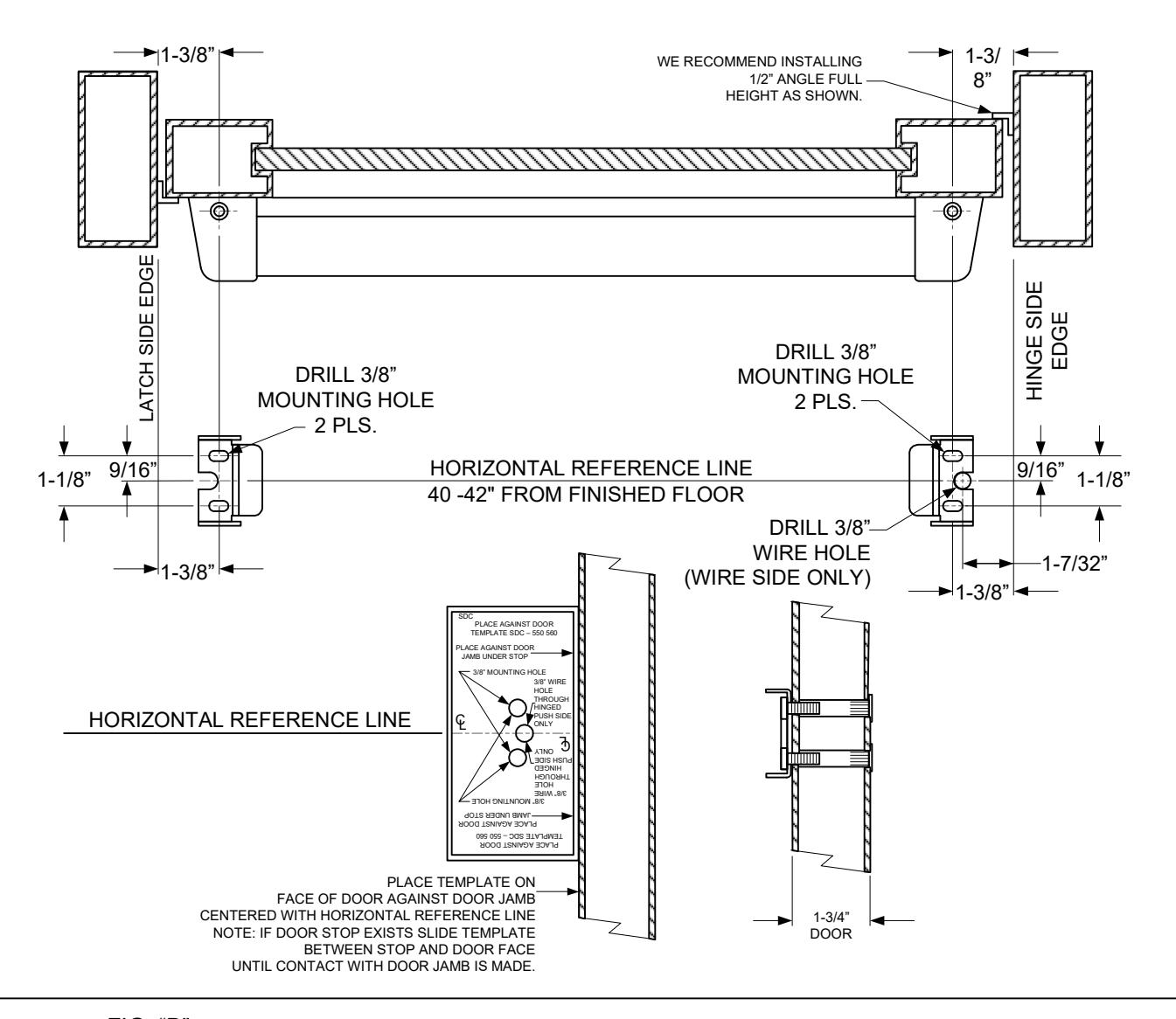
FIG. "B"
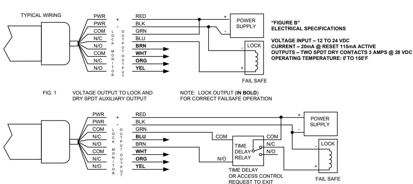
FIG. 2 DRY CONTACT OUTPUT TO TD OR ACCESS CONTROL AND DRY SPDT AUXILIARY OUTPUT
NOTE: LOCK OUTPUT (IN BOLD) FOR CORRECT FAILSAFE OPERATION