PS440B 480B Installation Instruction
Open the original PDF document
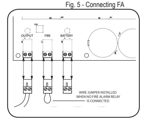
View PDFConnecting to the Fire Alarm Link (if needed)
- 1. Shut off the 120 VAC to the power supply.
- 2. Remove the jumper wire from "FIRE" terminal. (see fig 5)
- 3. Connect to normally closed fire alarm relay.
- 4. Restore AC voltage to power supply
| TROUBLESHOOTING | ||
|---|---|---|
| Symptom | Possible Cause | Solution |
|
EL Exit device can't fully
retract latch |
Possibility 1- Wire gauge from power supply to exit device too small | Check with your device manufacturer's wiring specifications. |
| Possibility 2- Distance from Power Supply. to exit device is too far | Check with your device manufacturer's wiring specifications. | |
| Possibility 3- Exit device out of adjustment | Re-adjust exit device according to manufacturer's mechanical recommendations. | |
|
Green channel LED won't
light up, channel isn't working |
Possibility 1- Dead short or overload | Shut off power, detect short, restore power, channel will reset. |
| Possibility 2- Bad solenoid in locking hardware or defective interface device between hardware and power supply. | Check solenoid coil resistance and compare to manufacturer spec. If not close, contact service representative. | |
|
Power supply not working
and red LED not lit. |
Possibility 1- AC fuse blown | Replace fuse with 2A Slow Blow 250VAC 5mm x 20mm |
| Possibility 2- Short Circuit | If replacement fuse has blown then there is likely a short circuit in the board & it will need to be replaced. | |
Installation Instructions PS440B/480B

DESCRIPTION
The PS440B and PS480B are regulated, linear power supplies rated at 4 Amps continuous but designed to provide the brief surge requited by 24VDC solenoid driven latch pull-back devices. These power supplies may also be used to power electrified mortise and cylindrical locks, electric strikes, mag locks, motorized exit devices, etc.
SPECIFICATIONS
- Input voltage: 120 VAC, 60Hz, 2 Amp Input Fuse
- Output voltage: Regulated 24VDC +/- 10%
- Current Rating: 4 Amps continuous, 6 Amp boost @ 20% duty cycle
- UL294 Sixth edition
- Class 2 Rated power limited output
- Inputs: PS404B: 4 Independent, solid-state inputs triggered by normally open dry contact PS408B: 8 Independent, solid-state inputs triggered by normally open dry contact
- Solid-State Outputs<sup>1</sup>:PS404B: 4 Auto resetting rated @ 1.5 Amp PS408B: 8 Auto resetting rated @ .75 Amp
- Enclosure: 13"W x 15.5"H x 5"D (accommodates two 7AH batteries)
- AC Fuse Type: 5mm x 20mm rated @2 Amp 250VAC
- LEDs: Red = A/C Power Indicator, Green = D/C Output Indicator, Orange = Battery Output Indicator
- Temperature Range: 0 to 49° C
- Fire Alarm Link
- Battery charging: Regulated, independent battery charging
- Battery backup: Automatic uninterrupted battery backup. Note: Battery capacity for emergency standby is at least 1 hour. Batteries not included (accommodates 2 each 7AH batteries)
- Maximum humidity: 85%
- Made in USA
- UL294 (6e) Security Levels: Destructive Attack: Level I Line Security: Level I Endurance: Level IV Standby Power: Level IV
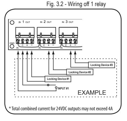
1. Total combined current for 24VDC outputs may not exceed 4A


Mounting Notes
- For UL Installations, the power supply must be installed in the protected area within an Access Controlled room
- 2. Must be Installed within accordance with the National Electrical Code, ANSI/NFPA 70.
- 3. Must be Installed within accordance with Local authority having jurisdiction.
-
4. The AC input wiring shall
- a. be in conduit,
- b. be minimum No. 18 AWG wire.
- c. maintain ¼ inch spacing between non power-limited wiring, and
- d. be fail safe to meet the requirements of NFPA 101, Paragraph 7.2.1.6.
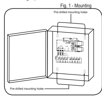
STEP 1 - Mount the power supply
- 1. Find a cool and dry location to mount the power supply.
- Using the four mounting holes in the power supply box, secure the box to a wall or other solid surface. (Note: The box is designed & approved for indoor use only.)
- 3. Proceed to step 2.
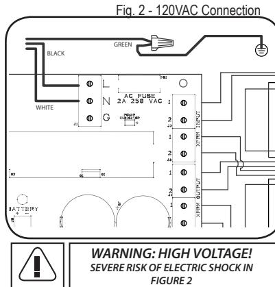
STEP 2 - 120VAC wiring connection
- Make sure 120VAC service is off at power supply (Breaker should be shut off).
- 2. Make sure 120VAC supply wire is rated at 90° C or higher.
- Connect 120VAC supply wire to the terminal block. Connect ground to pigtail attached to enclosure.
- 4. Restore AC power to power supply. Red LED should now be on.
- 5. Proceed to step 3.
STEP 3 - Wiring the Electrified Hardware
1. Shut off breaker supplying AC power to the power supply.
For firing devices independently continue to section A. Firing devices simultaneously proceed to section B.
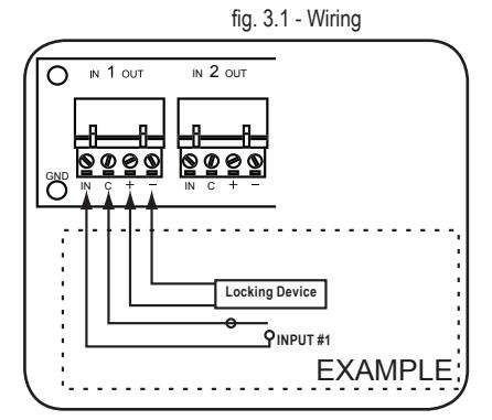
Section A.
- Using wiring diagram in fig 3.1, wire your exit devices.
- Restore power to power supply and trigger exit devices to make sure they are working correctly.
Section B.
- Using wiring diagram in fig 3.2, wire your exit devices.
- 2. Restore power to power supply and trigger exit devices to make sure they are working correctly.
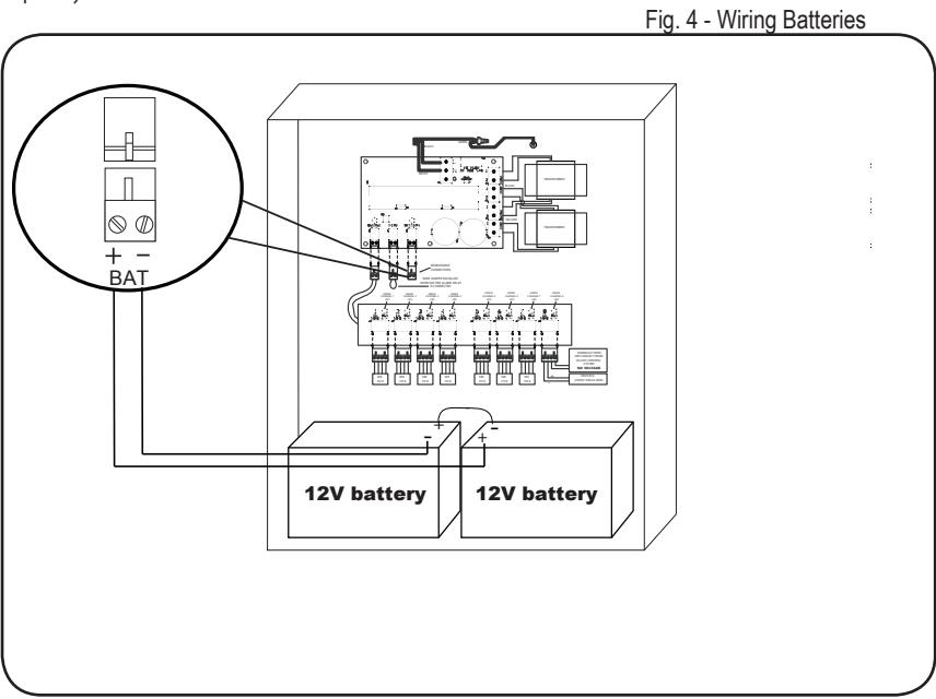
Wiring Batteries (Batteries not included)
- 1. Turn on 120VAC to power supply
- 2. WARNING: Make sure battery polarity is correct before you proceed.
- 3. Hook up batteries with battery leads as shown in fig 4. The enclosure will accommodate (2) 7AH 12V batteries.
NOTES:
- 1. When installing batteries for the first time or replacing old batteries make sure the batteries installed are fully charged.
- We recommend you label the battery with the date the batteries were installed. Most battery manufactures recommend the batteries be replaced after 4-5 years of service. You may want to check with your battery manufacturer when establishing a "replace by" date.