PS1 Installation Instruction
Open the original PDF document
View PDFInstallation Instructions PS1
Application: Designed specifically to supply power for EL latch pullback exit devices that operate at 24VDC.
FEATURES & SPECIFICATIONS
- Input voltage 120 VAC, 60Hz, 0.36 A
- Output rated 24 Vdc, 1 A
- (1) solid state input/output triggered by dry contact (No relay required)
- LEDs Red-Power indicator (LED 2) , Green-Channel indicator (LED 1)
- Temperature range 0 to 49° C
- Line voltage wiring shall be a minimum of 18 AWG in conduit
- All wiring that is not line voltage shall be a minimum of 22 AWG
- 1/4 inch spacing must be maintained between power-limited and nonpower-limited wiring
- Enclosure 10"W x 10"H x 4"D (12.5"W x 15"H x 5"D optional)
- Wiring from the FACP to be in accordance with NFPA 101, section 7.6.1.6.2
- Fuses AC= 2.0 A Slow Blow 250V 5m X 20mm


STEP 1 Mount the power supply
STEP 2 120 VAC wiring connection
Make sure 120VAC service is off at power supply PS1 (Breaker should be shut off).
Make sure 120VAC supply wire is rated at 90° C or higher.
Connect 120VAC supply wire to the AC input.
Connect ground wire to green pigtail attached to the enclosure chassis using the supplied wire nut.
Restore AC power to the power supply. Red LED should now be on.
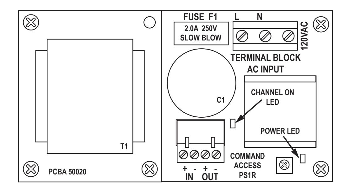
GREEN Fig 2 - AC wiring WHITE BLACK FUSE F1 2.0A 250V SLOW BLOW TERMINAL BLOCK CAUTION! HIGH VOLTAGE PRESENT ON AC INPUT. WARNING! FOR CONTINIOUS PROTECTION AGAINST FIRE. DISCONNECT AC POWER PRIOR TO SERVICING REPLACE ONLY WITH THE SAME TYPE AND RATING FUSE. ATTENTION! POUR UNE PRO REMPLACER UN ATTENTION! HAUTE TENSION PRÉSENT SUR L'ENTRÉE AC ENTION: TIAGTE TENSION SENT SUR L'ENTRÉE AC. CONNECT AC PUISSANCE AVANT L'ENTRETIEN. NE PROTECTION CONTINUE CONTRE LES INCENDIES. ACER UNIQUEMENT PAR LE MEME TYPE FUSE.
STEP 3 Wiring the devices
Shut off breaker supplying AC power to the power supply.
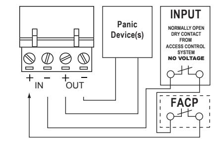
Wire your exit device(s) per the diagram(s).
NOTE: NO VOLTAGE ON INPUTS...DRY CONTACT ONLY
Restore power to power supply and trigger the device(s) to make sure they are working correctly.
STEP 4 Adjusting the Output Voltage
Fig 3.1 - Typical wiring diagram.
Fia 1 - Mountina
Panic Device(s) | NPUT | NORMALLY OPEN DRY CONTACT | ACCESS CONTROL SYSTEM NO VOLTAGE
Fig 3.2 Fire Alarm tie-in wiring diagram.
Pre-drilled
mounting holes
FUSE F1
0
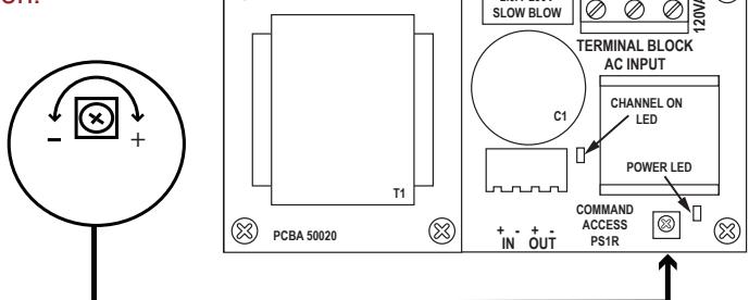
Fig 4 - Output Adjustment
(X)
NOTE: The output voltage cannot be adjusted in an UL installation.
To adjust output voltage, locate adjustment dial shown and go to step 2.
Turn adjustment dial clockwise to increase output voltage. Turn adjustment dial counter-clockwise to decrease output voltage.
| TROUBLESHOOTING | ||
|---|---|---|
| SYMPTOMS | POSSIBLE CAUSES | PROBLEMS |
|
EL Exit device can't fully
retract latch |
Possibility 1 - Wire gauge from pwer supply to exit device is too thin | Check with your device manufacturer's wiring specifications. |
| Possibility 2 - Distance from pwer supply to exit device is too far | Check with your device manufacturer's wiring specifications. | |
| Possibility 3 - Exit device out of adjustmernt | Re-adjust exit device according to manufacturer's mechanical recommendations. | |
| Power supply not working and red LED not lit | Possibility 4 - AC fuse blown | Replace fuse with a 5mm x 20mm, 2.0 A 250VAC, slow blow fuse only |