PM300D Installation Instruction
Open the original PDF document
View PDF

PM300/PM300D
INSTALLATION INSTRUCTIONS
The PM300 is a power booster interface module. It fits inside of an electric latch pullback exit device & gives it a local boost.
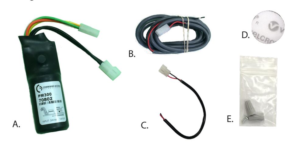
Includes
- A. PM300 Module
- B. 6' Power Lead
- C. 12" Retrofit Wiring Harness
- D. 3/4" Velcro
- E. Wire Connectors
Tools Required
• Wire Stripper
Specifications:
- Wires: Input to PM300 non-polarized Black (+)(-)
- Operating Voltage Range: 22-30 VDC
- Output from PM300: Yellow=Pull Coil; Orange= Hold Coil; Green=Common
- Fuse: Glass 3.5 5A, Resettable 1A trip
- Relay: 5A or greater
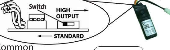
Standard Mode High Output Mode
- Fuse: Resettable 2A trip
- Relay: 10A or greater
Scan me
PM300 Compatibility Chart
Power Supply Options for PM300 and PM300D in Standard Mode :
The PM300 works best with the Command Access PS210, PS220/220B, PS440B, PS480B, PS1, PS2, & PS5 series regulated power supplies. The PM300 also works with most Regulated power supplies rated at 24VDC and 1.5A or higher. Although we do not recommend using power supplies that we have not thoroughly tested with the PM300. Please check our compatibility chart in the link below for a list of other manufacturers power supplies.
Power Supply Options for PM300 and PM300D in High Output Mode :
In High Output mode, the PM300 is designed for & MUST BE powered by the Command Access PS210, PS220/220B, PS440B, PS1, and PS5-4 power supplies only.
Note: High Output is recommended for sluggish devices, vertical rods, & overcoming door misalignment.
Wire Run Guidelines:
For best results we recommend that your maximum wire run not exceed the following:
18ga.= 700'

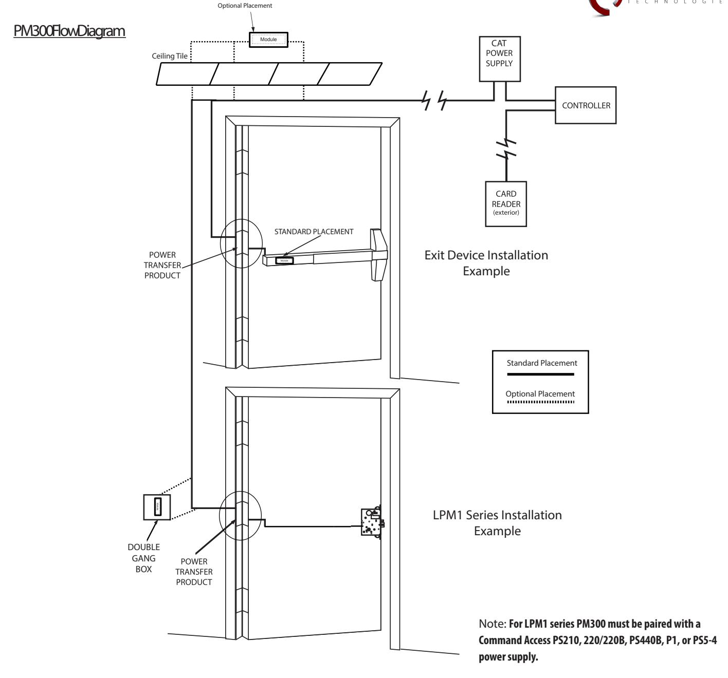
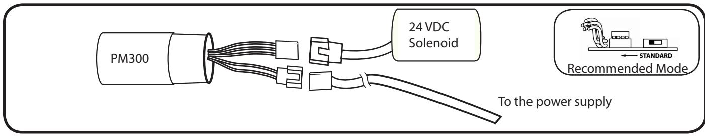
How to hook it up for Command Access & Von Duprin Devices:
The unit comes with an easy plug-in 3 prong connector that connects directly to Command Access and Von Duprin solenoids. There is a second easy plug-in 2 prong connector that connects to the 6' power lead. The 6' power lead should be connected to the positive and negative leads from the power supply.

How to hook it up for other Manufactures Devices:
The unit comes with a plug-in 3-prong wire harness that to retrofits to the existing solenoid. There is a second simple plug-in 2-prong wire harness that connects to the power from the power supply. Connect the power lead to the positive and negative leads from the power supply. Generic examples and specific retrofits explained below.
Adams Rite wire connections instructions:
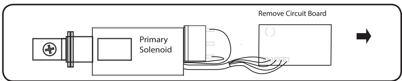
Remove pushbar and separate push pad from device to gain access to the solenoid/circuit board assembly.
Cut wires from Adams Rite Circuit board and remove board. A.
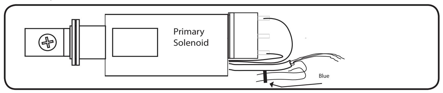
Tape back the two Blue wire. B.
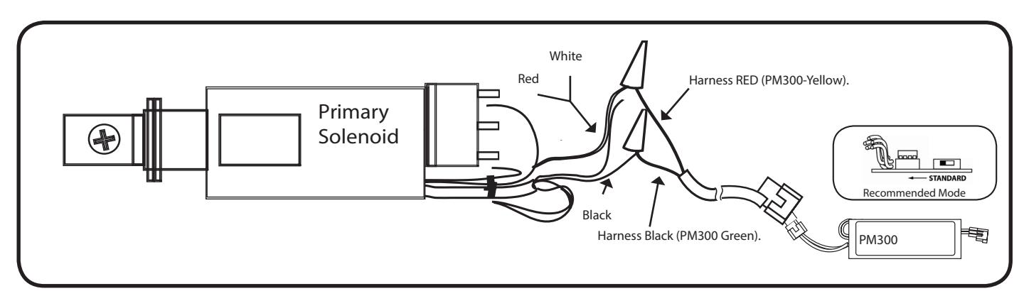
Connect White and Red wires from solenoid to RED wire from harness. Next, connect Black wire from solenoid to BLACK wire from harness. Next, connect PM300. C.

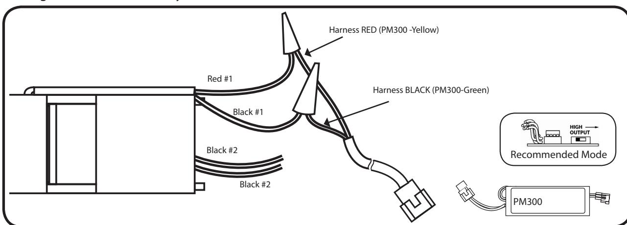
Corbin/Russwin wire connections instructions:
Remove pushbar and separate push pad from device to gain access to the solenoid/circuit board assembly.
A. Cut wires to disconnect solenoid from circuit board. Remove circuit board.
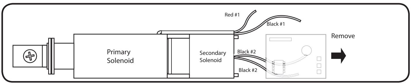
Connect Red #1 solenoid wire to RED harness wire. Next, connect Black #1 to BLACK harness wire. Disregard the two Secondary Black wires. Next, connect PM300. B.
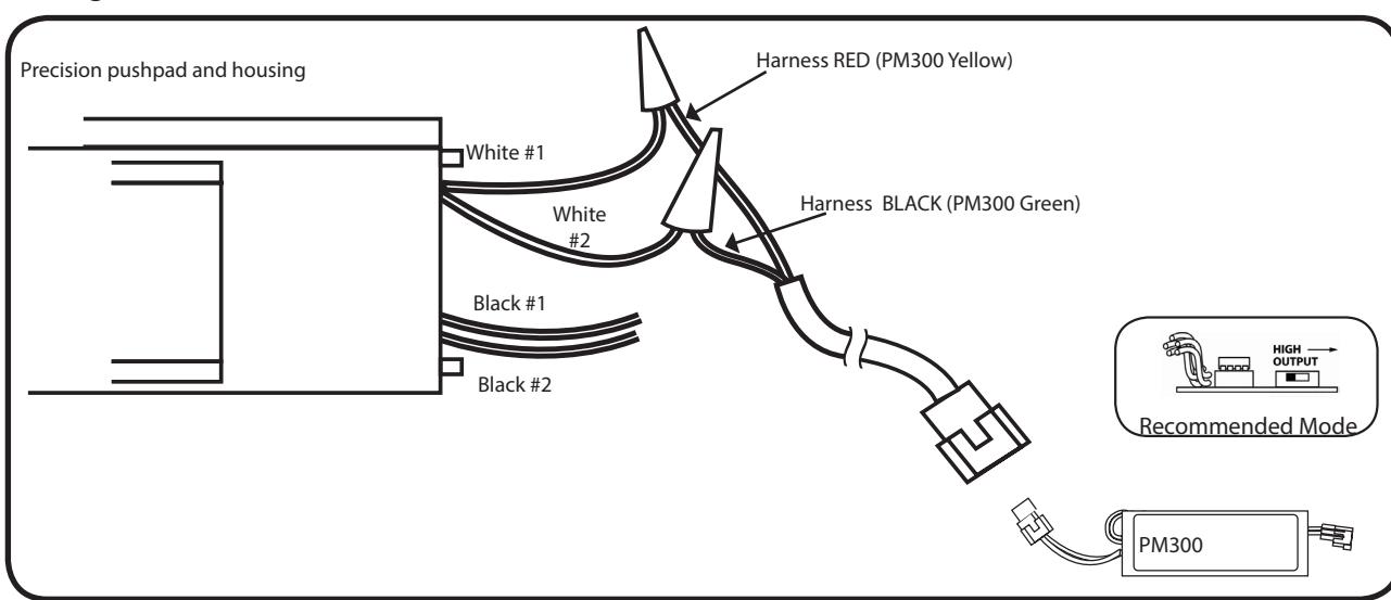
Precision wire connections instructions:
Page 4
Remove pushbar and separate push pad from device to gain access to the solenoid/circuit board assembly.
Connect primary White #1 wire to RED harness wire. Next connect White #2 wire to BLACK harness wire. Disregard both Black #2 wires. Next, connect PM300. A.