PG Passport 1000 Mortise Lock Installation Instructions
Open the original PDF document
View PDFInstallation Instructions

Passport 1000 PG
Mortise Lock

This product can expose you to lead which is known to the state of California to cause cancer and birth defects or other reproductive harm. For more information go to www. P65warnings.ca.gov.
1-800-727-5477 • www.sargentlock.com

Attention Installer: Improper installation may result in damage to the product and void the factory warranty.

| 1 | Warning3 | |
|---|---|---|
| 2 | General Description3 | |
| 3 | Hardware Specifi cations4 | |
| 4 | Electronics Specifi cations4 | |
| 5 | Parts Breakdown5 | |
| 6 | Installation Instructions - Door Preparation6 | |
| 7 | Installation Instructions - Change Hand of Lock Body8 | |
| 8 | Installation Instructions - Installation of Lock Body 10 | |
| 9 | Installation Instructions - Installation of Outside & Inside Lever Assembly Lock Body 10 | |
| 10 | Installation Instructions - Installation of Cylinder 11 | |
| 11 | Installation Instructions - Deadbolt Functions Only (82276 & 82277) 11 | |
| 12 | Installation Instructions - Gasket Installation (Optional) 12 | |
| 13 | Installation Instructions - Installation of Outside Escutcheon and Mounting Plate Assembly 12 | |
| 14 | Installation Instructions - Installation of Inside Component Assembly 13 | |
| 15 | Installation Instructions - Installation of Connectors 14 | |
| 16 | Installation Instructions - Battery / Battery Pack Installation and DIP Switch Setting Verifi cation 14 | |
| 17 | Installation Instructions - Installation of Inside Escutcheon 15 | |
| 18 | Installation Instructions - Application of Front Plate 15 | |
| 19 | Setting up the LockLink™ and Contact Card for First Use 16 | |
| 20 | LockSet Programming 17 | |
| 21 | Operational Check22 |

1 Warning
FCC
This equipment has been tested and found to comply with the limits for a Class B digital device, pursuant to Part 15 of the FCC Rules. These limits are designed to provide reasonable protection against harmful interference in a residential installation.
This equipment generates, uses, and can radiate radio frequency energy and, if not installed and used in accordance with the instructions, may cause harmful interference to radio communications. However, there is no guarantee that interference will not occur in a particular installation. If this equipment does cause harmful interference to radio or television reception, which can be determined by turning the equipment off and on, the user is encouraged to try to correct the interference by one or more of the following measures:
- Reorient or relocate the receiving antenna.
- Increase the separation between the equipment and receiver.
- Connect the equipment into an outlet on a circuit different from that to which the receiver is connected.
- Consult the dealer or an experienced radio/TV technician for help.
Industry Canada
Statement: The term "IC:" before the radio certifi cation number only signifi es that Industry Canada technical specifi cations were met.
This Class B digital apparatus meets all requirements of the Canadian Interference Causing Equipment Regulations. Operation is subject to the following two conditions: (1) this device may not cause harmful interference, and (2) this device must accept any interference received, including interference that may cause undesired operation.
Cet appareillage numérique de la classe B répond à toutes les exigences de l'interférence canadienne causant des règlements d'équipement. L'opération est sujette aux deux conditions suivantes: (1) ce dispositif peut ne pas causer l'interférence nocive, et (2) ce dispositif doit accepter n'importe quelle interférence reçue, y compris l'interférence qui peut causer l'opération peu désirée.
2 General Description
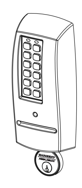
Designed specifi cally for the campus market, the SARGENT Passport 1000 PG Mortise Lock (powered by PERSONA) provides offl ine card/PIN access control, as well as detailed audit capabilities.
- The PG Offl ine unit is available with both keypad and magstripe card technology, or magstripe only.
- The PG operates on six (6) "AA" alkaline batteries and may be used for both indoor and outdoor applications.
Note: A weather-protective gasket is recommended for outdoor applications.

3 Hardware Specifi cations
- Stand alone, battery-operated
- Complete lockset with on-board memory
- Available with or without keypad (magstripe only)
- ADA compliant
- Easily retrofi ts existing PERSONA door preps (mortise)
- Latch Stainless steel
- Deadbolt Stainless steel
- Guardbolt Stainless steel, non handed
- Handing (RH/LH) can be specifi ed but is easily fi eld-reversible without disassembling the lock body
- Case 12 gauge heavy duty wrought steel
- Outside lever controlled by any combination of keypad, magstripe reader, or mechanical cylinder
- Inside lever retracts latch and deadbolt
- Locks furnished for 1-3/4" doors. Can be furnished for other door sizes upon request (consult factory)
- UL Listed (3 hr.)
4 Electronics Specifi cations
- Over 1 million users per door; 700 event transaction audit trail
- Multiple time zone and holiday access scheduling
- First-In unlock confi guration, either by time or by valid time or by user (selectable)
- Input Power: DC 9V, 1.5A through 6 AA Alkaline Batteries or Electrical Power
- Card Coercivity: HiCo (4000 Oersted) or LoCo (300 Oersted)
PERSONA Campus™ Online Software Features
- Use existing magstripe ID cards (high or low coercivity)
- New keycards can invalidate and reactivate key cards/users encoded quickly and easily through the "Conference Guest Wizard"
- Assign pre-defi ned access patterns and access points as well as keycard start and end times (group or individually)
- Importing student/personnel information is easy using the Import module
- Provide Deadbolt override at user-specifi ed doors for groups or individuals
- Connect to an external database for seamless integration of common information
- Remote technical support is available
- PERSONA Campus Online Software runs as a standalone system on a single PC or networked using existing TCP/IP networks

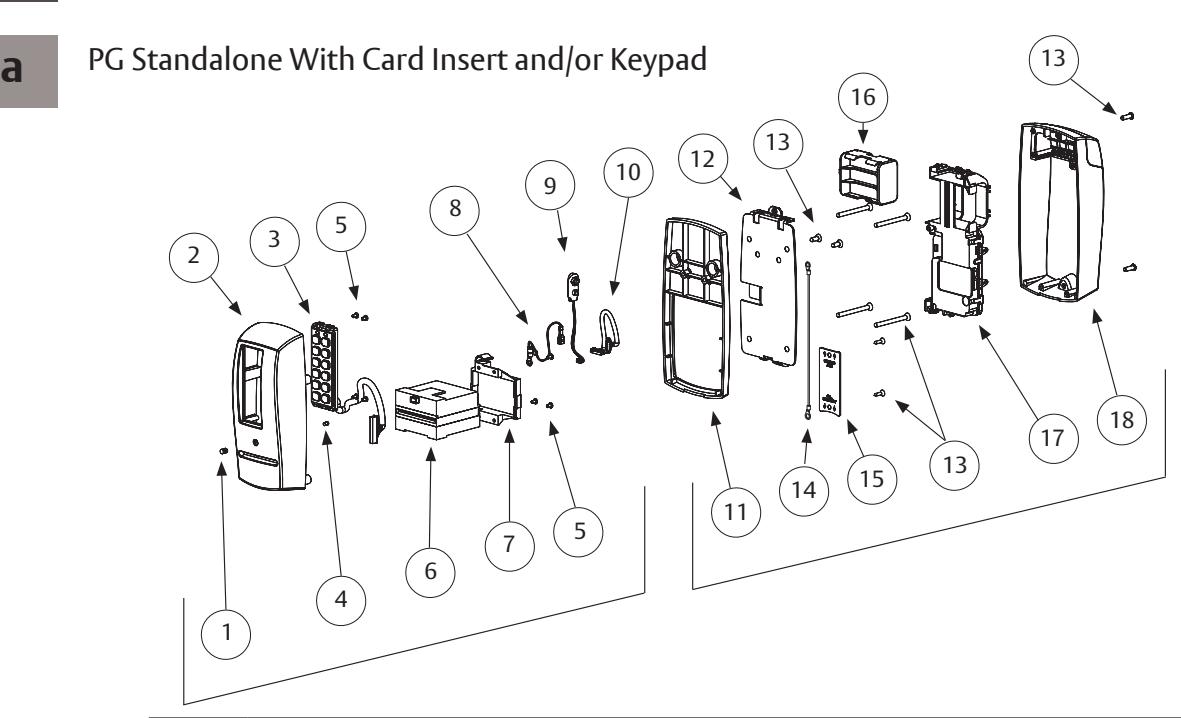
5 Parts Breakdown
| ITEM | PART NO. | DESCRIPTION |
|---|---|---|
| 1 | 52-0757 | Lens (Cliplite) |
| 2 | 52-0736 | Outside Passport Escutcheon (With Keypad) |
| 52-0737 | Outside Passport Escutcheon (Without Keypad) | |
| 3 | 52-3593 | Slim Style Keypad Assembly (KP-PG Only) |
| 4 | 52-0760 | Light Pipe (Cliplite) |
| 5 | 01-9299 | 4-40 X 3/16 Machine Screw |
| 6 | 52-0741 | LCU Card Reader |
| 7 | 52-0742 | Card Reader Mount |
| 8 | 52-2501 | Grounding Harness |
| 9 | 52-3597 | 9V Battery Harness |
| 10 | 52-3599 | Wire Harness LCU to Inteface PCB |
| 11 | 52-0875 | PG Passport 1000 Spacer (Included only with 1-3/8" thick doors) |
| 12 | 52-0748 | Inside Mounting Plate |
| 13 | 52-3804 | Screw Pack |
| 14 | 52-3906 | Grounding Harness |
| 15 | 52-0871 | Wire Cover Plate |
| 16 | 52-0751 | Battery Cartridge |
| 17 | 52-4245 | Modular Component |
| 18 | 52-3592 | Inside Escutcheon Assembly |

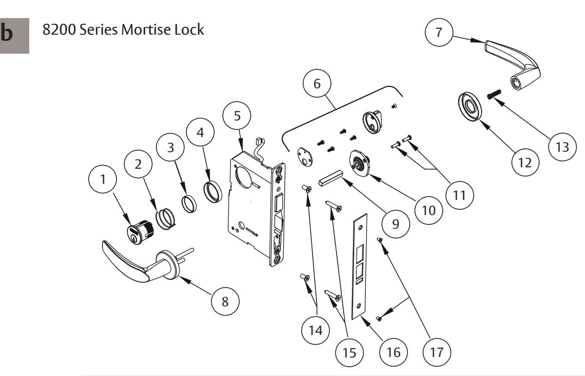
5 Parts Breakdown
| ITEM | PART NO. | DESCRIPTION |
|---|---|---|
| 1 | See catalog | Cylinder & Key Assembly |
| 2 | 13-0140 | Compression Spring |
| 3 | See catalog | Blocking Ring |
| 4 | See catalog | Cylinder Rosette |
| 5 | See catalog | Mortise Lock body |
| 6 | 77-2591 Tab | Turn Lever Assembly |
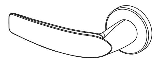
| 7 | See catalog | Inside Lever Handle |
| 8 | See catalog | Outside Lever Assembly |
| 9 | 82-0368 | Spindle |
| 10 | 82-3088 | Inside Lever/knob Adapter Plate Assembly |
| 11 | 01-1495 | 8-32 X 5/8 Machine Screw |
| 12 | See catalog | Mortise Rose |
| 13 | 82-0347 | Spindle Spring |
| 14 | Cr-fhm1 | 1/4-20 X 1/2 Machine Screw |
| 15 | Cr-fhws | 12 X 1-1/4 Wood Screw |
| 16 | 82-0084 | Outside Front, Stamped |
| 17 | 01-0028 | 8-32 X 1/4 Machine Screw |

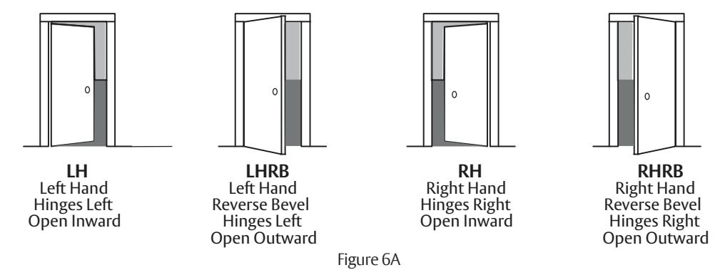
6 Installation Instructions - Door Preparation
a Verify Hand and Bevel of Door
Stand on outside/locked side of door when determining the door hand.
b Door Preparation
Prior to installation, all holes must be free of burrs, debris and sharp edges.
If doors are not properly reinforced per ANSI 115.2, commercially available reinforcements should be installed. Prepare door according to appropriate template:
- Field template A7949 (or wood doors).
- Manufacturer's template 4629 (for metal doors).
1-800-727-5477 • www.sargentlock.com
A7807D 12/22

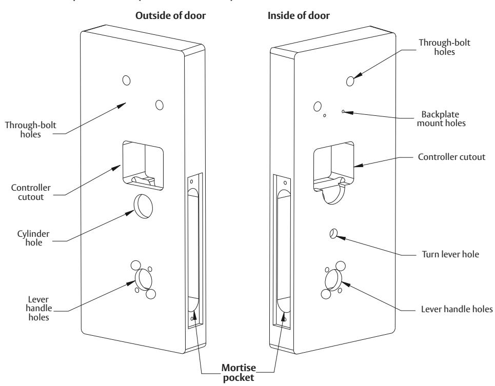
6 Installation Instructions - Door Preparation
c Prepare Lock Body
NOTE: Lock body is shipped with a removable perforated sticker covering the retaining ring on the non-cylinder side (inside of door) of the lock body.
Cables and connectors are coiled inside the retaining ring.
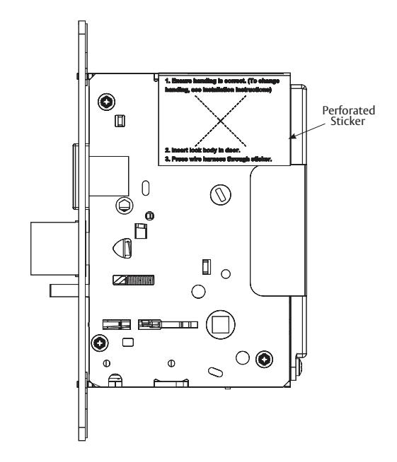
• If the handing of the lock body does not need to be changed, skip 2 and proceed to 3.
The lock body sticker states the following:
- 1. Ensure the handing is correct. (To change handing, see Installation Instructions - Change Hand of Lock Body.)
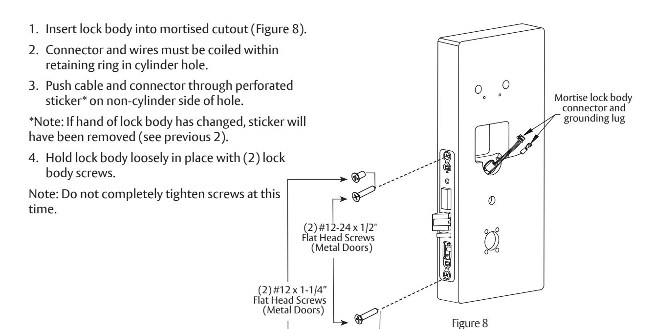
- 2. Insert lock body in door.
- 3. Press wire harness through sticker.
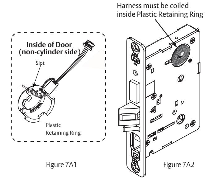
7 Installation Instructions - Change Hand of Lock Body
a Retaining Ring
- 1. Peel back the sticker that covers the retaining ring and remove the retaining ring.
- 2. Orient the plastic retaining ring so that the word BOTTOM is located at the bottom of the cylinder hole (Figure 7A1).
- 3. Route the wires from the top of the cylinder hole into the slot on the top of the plastic retaining ring, NOT through the retaining ring (Figure 7A2) and insert the retaining ring into the non-cylinder side of the cylinder hole.
- 4. The cable and connector must be coiled inside retaining ring before inserting mortise into door prep pocket (Figure 7A2). Make sure the plastic retaining ring is seated correctly.

7
Installation Instructions - Change Hand of Lock Body, continued
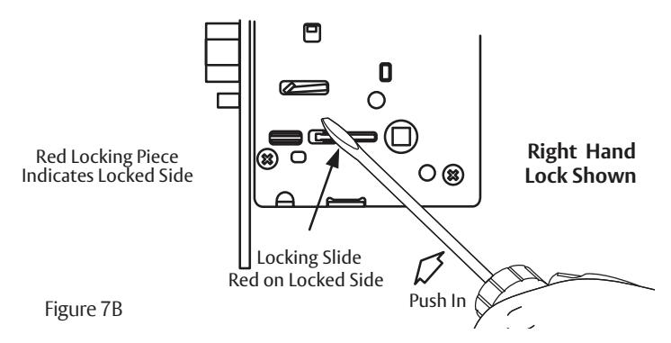
b
Reverse Lock Hand
Red surface of locking piece must face the outside/locked side of door. To rotate locking piece (Figure 7B):
- 1. Position lock body with red surface of locking piece visible.
- 2. Insert blade type screwdriver into locking piece slot to rotate locking piece toward back of lock body.
- 3. Rotate the locking piece 180° until RED surface is on opposite side.
Note: Red indicates locked side (outside). Wire harness MUST exit through the non-cylinder side (inside) of the lock body (Figure 7C).
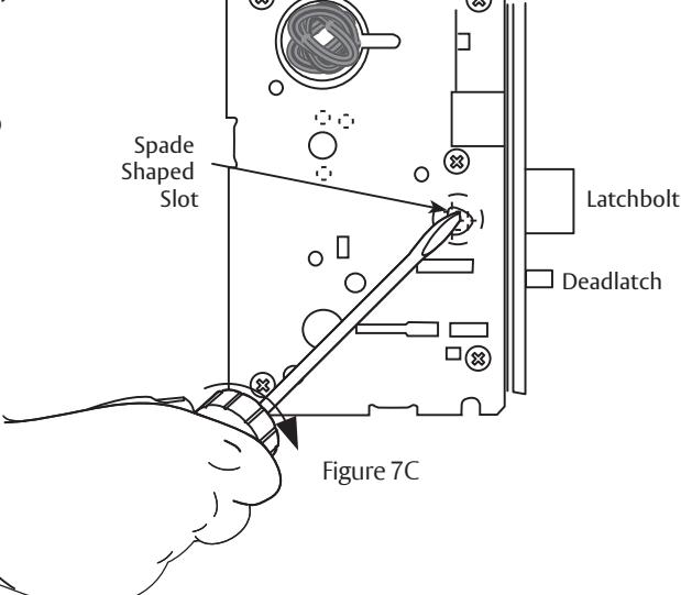
C
Reverse Latch Hand
Beveled surface of latchbolt must face strike (Figure 7C1). The deadlatch is self adjusting.
To change the hand of the latchbolt:
- 1. Insert the blade of a slotted screwdriver (>1/4") into the spade shape slot behind latch.
- 2. Rotate the screwdriver 90° to push latchbolt out until back of bolt clears lock case front.
- 3. Rotate latchbolt 180° until the latchbolt drops back into the lock body.
Note: Latch cannot be unscrewed.
8 Installation Instructions - Installation of Lock Body
9
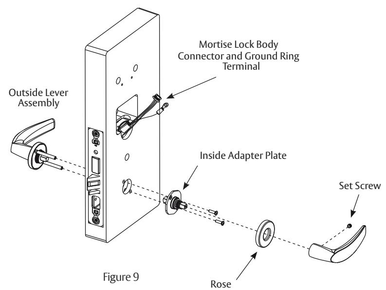
Installation Instructions - Installation of Outside & Inside Lever Assembly Lock Body
Align through bolt posts on outside lever assembly with door prepped holes (Figure 9).
- 1. Slide the outside lever assembly with spindle though the door and lock body.
- 2. Secure lever assembly with the inside adapter plate with (2) screws:
DO NOT TIGHTEN.
- 3. Securely tighten the lock body screws on edge of door.
- 4. Securely tighten both inside adapter screws.
- 5. Place rose over inside adapter and tighten clockwise.
- 6. Fasten inside lever to inside adapter and tighten lever set screw snugly.

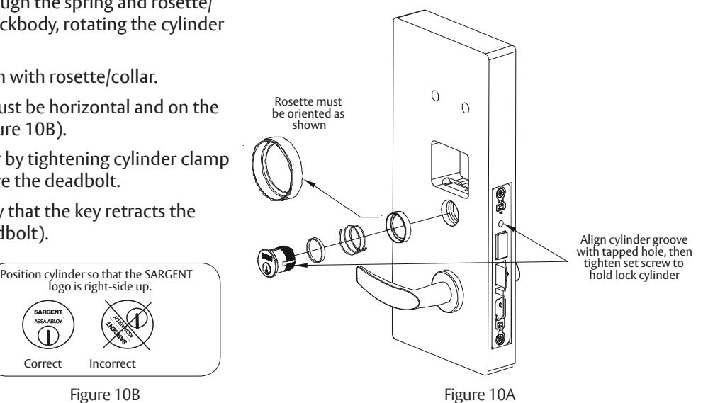
10 Installation Instructions - Installation of Cylinder
Note: For proper cylinder/parts orientation see Figure 10A. Slide cylinder through the spring and rosette/ collar and screw into lockbody, rotating the cylinder clockwise.
Cylinder should be fl ush with rosette/collar.
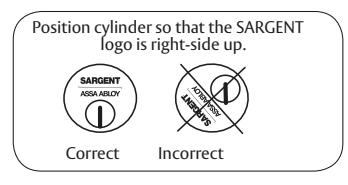
Note: SARGENT logo must be horizontal and on the top of the cylinder (Figure 10B).
- 1. Secure the cylinder by tightening cylinder clamp screw located above the deadbolt.
- 2. Using the key, verify that the key retracts the latchbolt (and deadbolt).
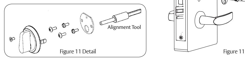
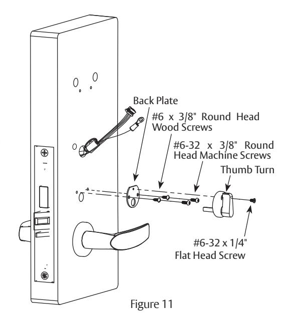
11 Installation Instructions - Deadbolt Functions Only (82276 & 82277)
- 1. Insert alignment tool (supplied) into lock body thumb turn.
- 2. Slide back plate over tool and make level.
- 3. Secure back plate to door with two (2) #6 x 3/8" round head wood screws or #6-32 x 3/8" round head machine screws.
- 4. Dispose of tool, position thumb turn over back plate (Figure 11) and secure with #6-32 x 1/4" fl at head screw.
Note: Thumb turn should cover screw head when deadbolt is retracted.
5. Refer to instructions (A5675G) included in package included with lock.
A7807D 12/22

13
12 Installation Instructions - Gasket Installation (Optional)
Note: Optional, for non-fi re rated doors only.
For non-fi re rated door applications, an optional gasket (Figure 12) may be used as a weather seal between the escutcheon and the outside door surface.
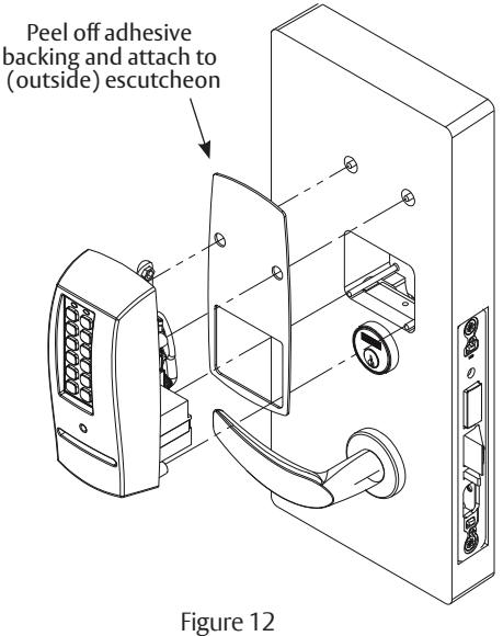
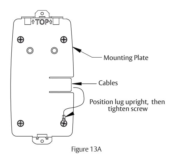
Installation Instructions - Installation of Outside Escutcheon and Mounting Plate Assembly
- 1. Insert the mounting posts through holes as shown.
- 2. On the inside of the door, position the mounting plate over the indicated holes.
Note: Feed controller and keypad cables through side opening (Figure 13A).
12

13
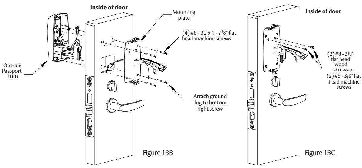
Installation Instructions - Installation of Outside Escutcheon and Mounting Plate Assembly, continued
Cable from lock body feeds thru bottom (Figure 13A and 13B).
- 3. Attach grounding lug to bottom right screw and note upright positioning of lug as shown (Figure 13B).
- 4. Insert other three corner screws and tighten, fastening the outside escutcheon to the door (Figure 13B). IMPORTANT: If the following step is skipped, the product will not be UL-compliant:
- 5. Attach two (2) #8 x 3/8" fl at head wood screws for wood doors, or (2) #8-32 x 3/8" fl at head machine screws for metal doors (Figure 13C).
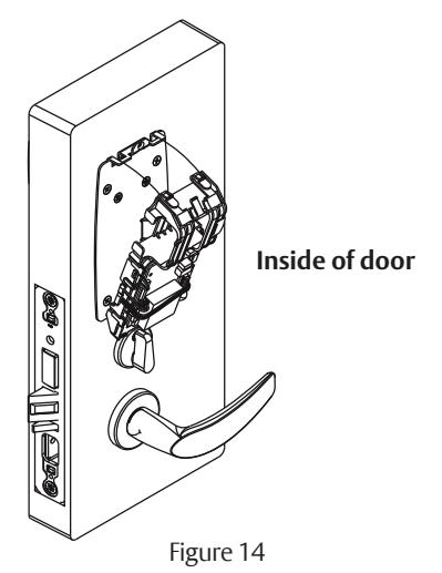
14 Installation Instructions - Installation of Inside Component Assembly
Insert bottom of component assembly fi rst (Figure 14), then clip top of component assembly to backplate, verifying both tabs attached securely.
A7807D 12/22

15 Installation Instructions - Installation of Connectors
Secure the following connectors onto the circuit board (Figure 15 and Detail):
Note: Connectors go on only one way. Do not force and do not offset connectors.
Be sure they are completely seated (fl ush).
- 1. Secure the mortise lock body assembly connector (10-pin).
- 2. Secure the mortise keypad/ card reader connector (14-pin).
- 3. Secure the LCU connector (7-pin).
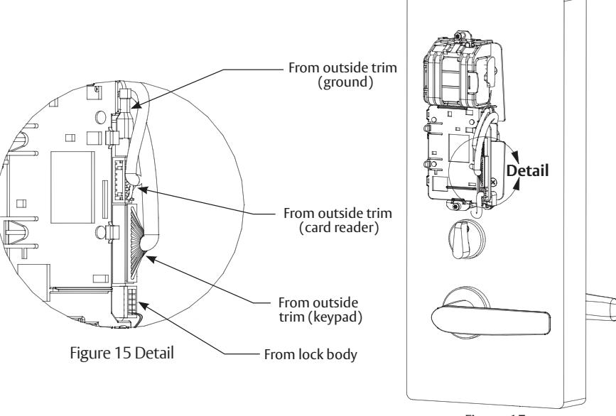
Figure 15
16
Installation Instructions - Battery / Battery Pack Installation and DIP Switch Setting Verifi cation
- 1. Place (6) "AA" batteries into the compartment being careful to align polarity (- & +) properly.
- 2. Insert battery pack and click into place, making sure polarity terminals on the battery pack are oriented upwards (Figure 16).
- 3. Verify DIP switch settings are correct for the application.
PERSONA PG Controller DIP Switch Settings (Fig 10A):
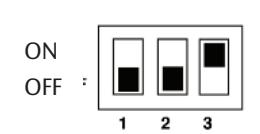
SARGENT mortise lock with and without deadbolt:
- Switch 1 and 2 OFF
- Switch 3 ON
ON OFF
SARGENT cylinder or exit locks:
- Switch 1 OFF
- Switch 2 and 3 ON
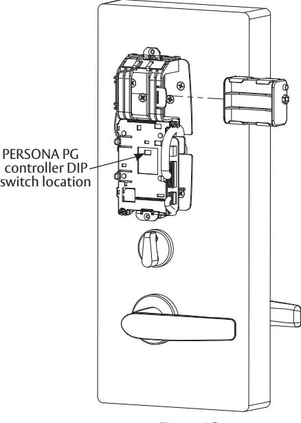
Figure 16

17 Installation Instructions - Installation of Inside Escutcheon
- 1. Position inside escutcheon.
- 2. Insert screws, top and bottom, and tighten securely. DO NOT OVERTIGHTEN.
Note: All wires should be placed inside to avoid being pinched.
3. Straighten escutcheon and tighten securely.
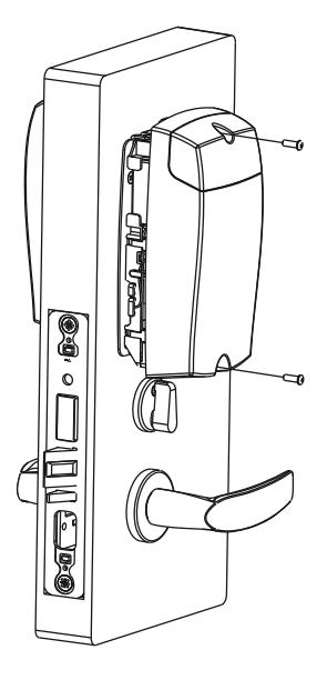
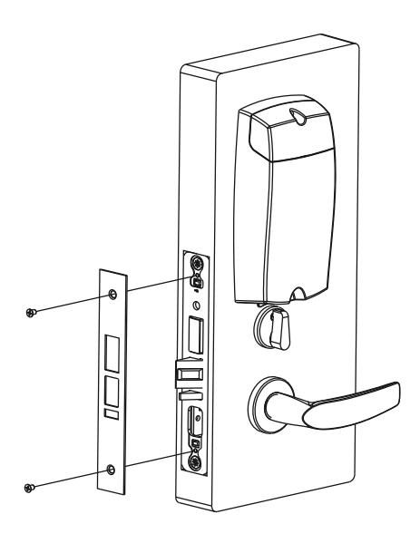
18 Installation Instructions - Application of Front Plate
Attach front plate with (2) #8-32 X 1/4" fl at head screws.

19 Setting up the LockLink™ and Contact Card for First Use*
*NOTE: The following steps in this section are only performed one time. Once Bluetooth pairing is complete, these steps do not need to be repeated to program locks (Section 8 "Lockset Programming")
a Pairing the Pocket PC with the Contact Card
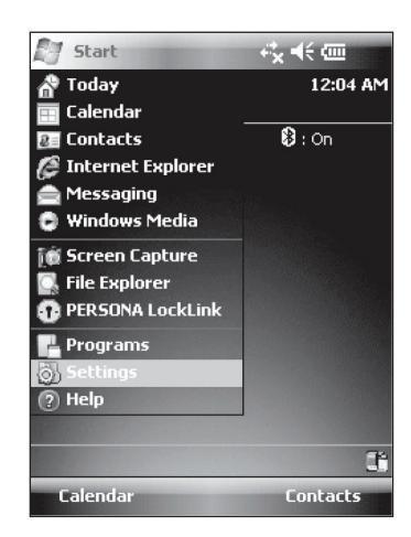
- 1. To begin, highlight (by tapping) the button and select the 'Settings' menu.
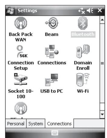
- 2. Next, tap the 'Connections' tab at the bottom of the screen and highlight the Bluetooth icon from the 'Settings' menu.
3. Insert the Contact Card into a lock (provides power to Contact Card) and then select "Add New Device..."
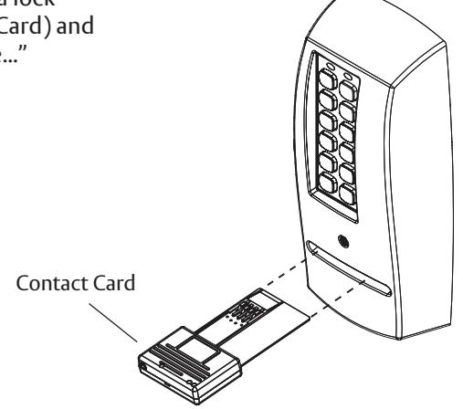
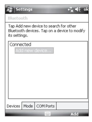
-
4. The Pocket PC will enable Bluetooth and begin discovery. If you receive a warning, "No Devices Found," then check again to see the blue light fl ashing on the Contact Card and tap 'Retry'.
- If the blue light is not fl ashing, remove the Contact Card, wait for the lights to go dark, then reinsert it before tapping 'Retry'.
- If this step fails repeatedly, then contact PERSONA technical support at (800)–481–8464.

19 Setting up the LockLink™ and Contact Card for First Use, continued
b Confi guring the LockLink™ Software
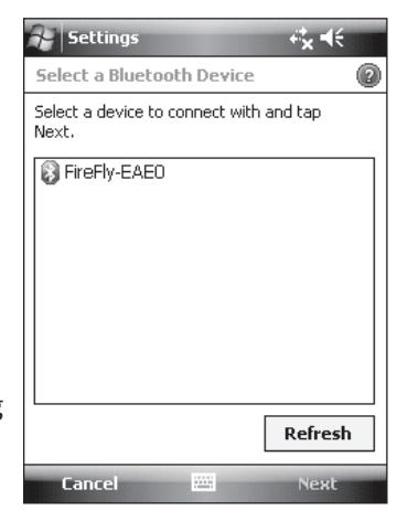
- 1. When the list entry appears, highlight it and tap 'Next'.
- 2. Enter "1234" when prompted for 'Passcode.'
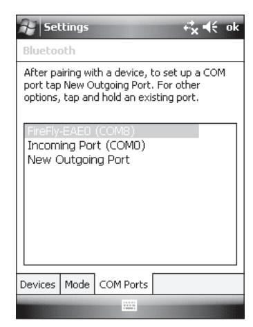
- 3. Tap the 'COM Ports' tab at the bottom of the screen. Note the COM port number assigned to the Firefl y device.
NOTE: If you do not see the FireFly-EAE0 device in the COM port list, tap 'New Outgoing Port' and pick the FireFly-EAE0 device before tapping 'Next'.
4. Choose an available COM port number (COM8 is often a good choice) and tap 'Finish."
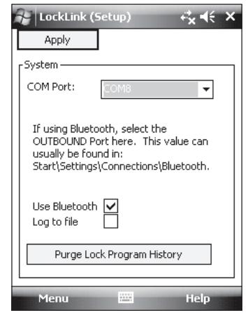
20 LockSet Programming
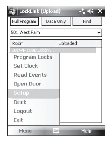
- 1. Tap then tap to launch the LockLink program.
- 2. Choose Menu and then 'Setup'.
- 3. Select the COM port noted in Step 3 of Section 20b.
- 4. Check the 'Use Bluetooth' box and tap 'Apply'.

20 LockSet Programming, continued

a Start the PERSONA LockLink™ Software
- 1. Tap on the Pocket PC Screen.
- 2. If visible, select PERSONA LockLink™ to launch the program; otherwise, tap Start and Programs to launch the Programs list and then select the PERSONA LockLink™ icon (right).
- 3. Log into the LockLink™ by tapping the arrow and selecting your username from the drop down list:
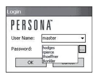
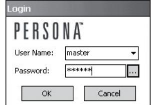
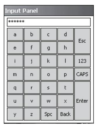
- 4. Type in your password. You can use the onscreen keyboard entry method to enter information.
- 5. To access the full screen keyboard (shown at right) tap on the ellipsis (three dots) next to the password fi eld.
Once you have entered your password, you will begin on the Upload screen. This is the proper place to be for programming locks.
Note: Be sure to perform an Operational Check (see Section 9) for each lock.

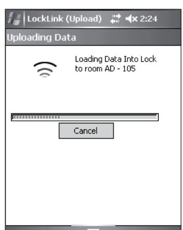
b Upload Full Program
After locks are installed, they must have program fi les copied into them before they can receive and interpret data. In many ways, the program fi les act as the locks' operating system by interpreting the lock data to control each lock's behavior.
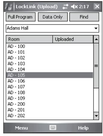
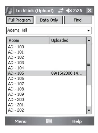
1. Highlight (by tapping) the name of the lock that you wish to program.
If the list of locks is longer than the display, locate the lock using the scroll bar at the right of the display or use the button at the top of the display.
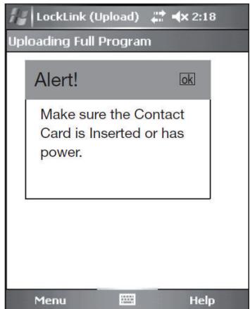
- 2. Tap the button to completely initialize the lock; the message "Alert! Make sure the Contact Card is Inserted or has power."
- 3. Tap "ok."

20 LockSet Programming, continued

b Upload Full Program, continued
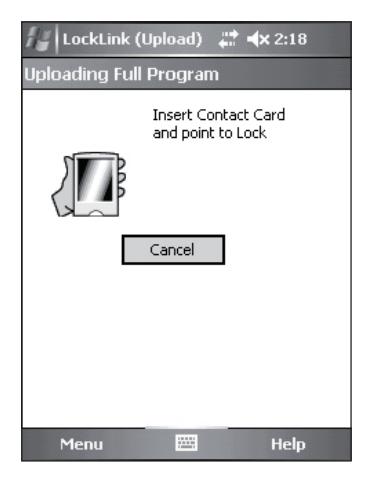
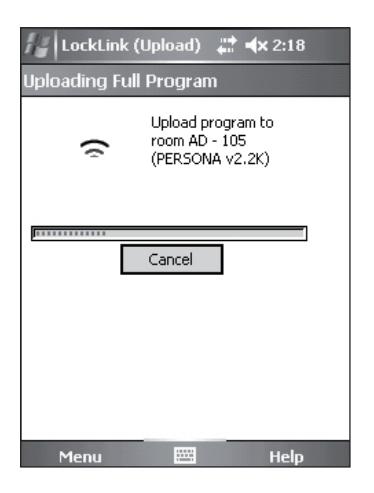
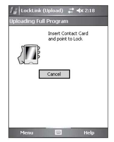
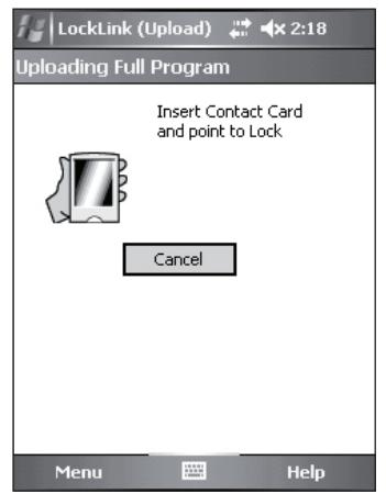
4. Follow the directions on the screen.
NOTE: You will be prompted to insert the Contact Card into the lock three times.
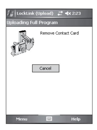
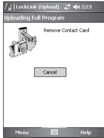
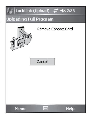
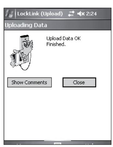
5. When the data has fi nished loading, you are notifi ed to remove the Contact Card from the lock.
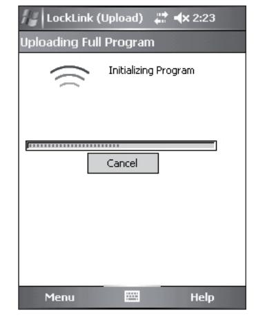
6. Reinsert Contact Card a second time to initialize the program.
Note: You should hear the motor run briefl y.

20 LockSet Programming, continued

b Upload Full Program, continued
7. Program initializes and directs you to remove the Contact Card.
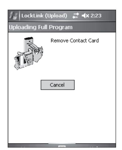
8. Follow the on-screen directions and reinsert the Contact Card a third time.
- 9. Remove the Contact Card.
- 10. To exit and return to the program screen, tap the button.

20 LockSet Programming, continued

b Upload Full Program, continued
- 11. After programming the new lockset, verify operation by performing the Operational Check (refer to Section 22).
- 12. Repeat this procedure for each lock to be programmed with lock data.
NOTE: With a successful upload, the time and date that the lock was programmed will appear beside each lock name.

21 Operational Check
IMPORTANT: Be sure to test functions prior to closing door. In all cases, perform the following checks:
-
1. Ensure that inside lever retracts latch (and deadbolt for deadbolt functions).
- For devices with cylinders, the following checks apply:
Insert key into cylinder and rotate:
- a. There should be no friction against lock case, wire harness, or any other obstructions. If harness friction exists, refer to the section on 'Installation of Inside Component Assembly' in PERSONA instructions A7807 (this manual).
- b. The key should retract the latch and the key should rotate freely.
- c. The key should extend and retract the latchbolt.
- For units without a keypad, the following checks apply:
Insert test card marked NO PIN and retract:
- a. Ensure lockset displays a green fl ash (and no other lights).
- b. Ensure outside lever retracts latch, the door opens, and that there is no binding against lock case, wire harness or other obstructions.
- For units with a keypad, test the keypad by using the following checks:
Create and insert a test card marked 'PIN 1234' and retract:
- a. Ensure lockset displays solid yellow light.
- b. Type 1, 2, 3, 4 on keypad.
- c. Ensure outside lever retracts latch, the door opens, and that there is no binding against lock case, wire harness or other obstructions.
- d. Test again with card marked 'PIN 5678'.
- e. Test again with card marked 'PIN 9090'.
- 2. Any rapid yellow or rapid red fl ashing lights indicate a low power condition. Check the battery voltage at the top of the battery pack to check for the required 9V. If the voltage is correct, inspect the wiring for a possible short.
- 3. When you have completed the tests, close the door, ensuring latchbolt and deadbolt fully extend into strike plate without binding.

Company is prohibited. Patent pending and/or patent www.assaabloydss.com/patents.