PG Passport 1000 Exit Device Installation Instructions
Open the original PDF document
View PDF

A7809C 01/18
Table of Contents
| 1 | Warning | 2 |
|---|---|---|
| 2 | General Description | 3 |
| 3 |
Hardware Specifications
|
3 |
| 4 | Electronic Specifications | 3 |
| 5 | Part Breakdown | 4 |
| 6 |
Rim Type 8877/8878 Exit Device Installation
|
8 |
| 7 |
Mortise Type 8977/8978 Exit Device Installation
|
14 |
| 8 |
Setting up the PERSONA LockLink™
& Contact Card |
20 |
| 9 | Lockset Programming | 23 |
| 10 |
Operational Check
|
27 |
1 Warning
Changes or modifications to this unit not expressly approved by the party responsible for compliance could void the user's authority to operate the equipment.
FCC
This equipment has been tested and found to comply with the limits for a Class B digital device, pursuant to Part 15 of the FCC Rules. These limits are designed to provide reasonable protection against harmful interference in a residential installation.
This equipment generates, uses, and can radiate radio frequency energy and, if not installed and used in accordance with the instructions, may cause harmful interference to radio communications. However, there is no guarantee that interference will not occur in a particular installation. If this equipment does cause harmful interference to radio or television reception, which can be determined by turning the equipment off and on, the user is encouraged to try to correct the interference by one or more of the following measures:
- Reorient or relocate the receiving antenna.
- Increase the separation between the equipment and receiver.
- Connect the equipment into an outlet on a circuit different from that to which the receiver is connected.
- Consult the dealer or an experienced radio/TV technician for help.
Industry Canada:
Statement: The term "IC:" before the radio certification number only signifies that Industry Canada technical specifications were met.
This Class B digital apparatus meets all requirements of the Canadian Interference Causing Equipment Regulations. Operation is subject to the following two conditions: (1) this device may not cause harmful interference, and (2) this device must accept any interference received, including interference that may cause undesired operation.
Cet appareillage numérique de la classe B répond à toutes les exigences de l'interférence canadienne
causant des règlements d'équipement. L'opération est sujette aux deux conditions suivantes: (1) ce dispositif peut ne pas causer l'interférence nocive, et (2) ce dispositif doit accepter n'importe quelle interférence reçue, y compris l'interférence qui peut causer l'opération peu désirée.
! Observe precautions for handling electrostatic sensitive devices.
SARGENT Mfg. Co. Passport 1000 locksets utilizing a door position switch (DPS) are not rated for, or intended for use in life safety applications.
Any retrofit or other field modification to a fire rated opening can potentially impact the fire rating of the opening, and SARGENT Manufacturing makes no representations or warranties concerning what such impact may be in any specific situation. When retrofitting any portion of an existing fire rated opening, or specifying and installing a new fire-rated opening, please consult with a code specialist or local code official (Authority Having Jurisdiction) to ensure compliance with all applicable codes and ratings.
2 General Description
Designed specifically for the campus market, the SARGENT Passport 1000 PG Rim/Mortise Exit Device (powered by PERSONA) provides offline card/PIN access control, as well as detailed audit capabilities.
- The PG stand alone unit is available with both keypad and magstripe card technology, or magstripe only.
- The PG operates on six (6) "AA" alkaline batteries and may be used for both indoor and outdoor applications.
Note: A weather-protective gasket is recommended for outdoor applications.
Items Supplied with Exit Device
Items included in your 8877 and 8977 Series Exit Device carton:
- Outside Escutcheon with Keypad
- Outside Motorized Trim Assembly
- Exit Device
- Mortise cylinder for 8977
- Rim cylinder for 8877
- Inside Escutcheon with Circuit Board and Battery Pack
- 6 "AA" alkaline batteries
- Screw Pack
Items included in your 8878 and 8978 Series Exit Device carton:
- Outside Escutcheon with Keypad
- Outside Motorized Trim Assembly
- Exit Device
- Inside Escutcheon with Circuit Board and Battery Pack
- 6 "AA" alkaline batteries
- Screw Pack
3 Hardware Specifications
Passport 1000 PG Rim Exit
- Latch 3/4" throw, stainless steel
- Outside motor driven "ET" lever controlled by keypad
- Push bar retracts latch from inside
- Fire stop provided on all lever handle designs
- SARGENT exit devices furnished for 1-3/4" doors
- UL Listed
- Accepts all SARGENT rim cylinders (8877 only)
- Key retracts latch (8877 only)
- Available in "ET" lever handle designs only
Passport 1000 PG Mortise Exit
- Latch 3/4" throw, anti-friction, brass
- Outside motor driven "ET" lever controlled by keypad
- Push bar retracts latch from inside
- Fire stop provided on all lever handle designs
- SARGENT exit devices furnished for 1-3/4" doors
- UL Listed
- Accepts all SARGENT mortise cylinders (8977 only)
- Key retracts latch (8977 only)
- Available in "ET" lever handle designs only
4 Electronic Specifications
- Over 1 million users per door; 700 event transaction audit trail
- Multiple time zone and holiday access scheduling
- First-In unlock configuration, either by time or by valid time or by user (selectable)
PERSONA Campus™ Online Software Features
- Use existing magstripe ID cards (high or low coercivity)
- New keycards can invalidate and reactivate key cards/users – encoded quickly and easily through the "Conference Guest Wizard"
- Assign pre-defined access patterns and access points as well as keycard start and end times (group or individually)
- Importing student/personnel information is easy using the Import module
- Input Power: DC 9V, 1.5A through 6 AA Alkaline Batteries or Electrical Power
- Card Coercivity: HiCo (4000 Oersted) or LoCo (300 Oersted)
- Provide Deadbolt override at user-specified doors for groups or individuals
- Connect to an external database for seamless integration of common information
- Remote technical support is available
- PERSONA Campus Online Software runs as a standalone system on a single PC or networked using existing TCP/IP networks
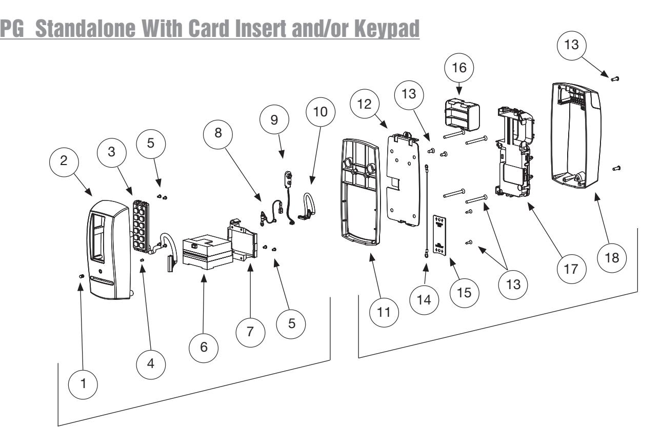
| ITEM | PART No. | DESCRIPTION |
|---|---|---|
| 1 | 52-0757 | Lens (Cliplite) |
| 52-0736 | Outside Passport Escutcheon (With Keypad) | |
| 2 | 52-0737 | Outside Passport Escutcheon (Without Keypad) |
| 3 | 52-3593 | Slim Style Keypad Assembly (KP-PG Only) |
| 4 | 52-0760 | Light Pipe (Cliplite) |
| 5 | 01-9299 | 4-40 X 3/16 Machine Screw |
| 6 | 52-0741 | LCU Card Reader |
| 7 | 52-0742 | Card Reader Mount |
| 8 | 52-2501 | Grounding Harness |
| 9 | 52-3597 | 9V Battery Harness |
| 10 | 52-3599 | Wire Harness LCU to Inteface PCB |
| 11 | 52-0875 | PG Passport 1000 Spacer (Included only with 1-3/8" thick doors) |
| 12 | 52-0748 | Inside Mounting Plate |
| 13 | 52-3804 | Screw Pack |
| 14 | 52-3906 | Grounding Harness |
| 15 | 52-0871 | Wire Cover Plate |
| 16 | 52-0751 | Battery Cartridge |
| 17 | 52-4245 | Modular Component |
| 18 | 52-3592 | Inside Escutcheon Assembly |
01/31/18
Copyright © 2018, Sargent Manufacturing Company, an ASSA ABLOY Group company. All rights reserved. Reproductions in whole or in part without express written permission of Sargent Manufacturing Company is prohibited.
Parts Breakdown (Continued) 8877/8878 x ET x Lever Design Passport 1000 Rim Exit Device
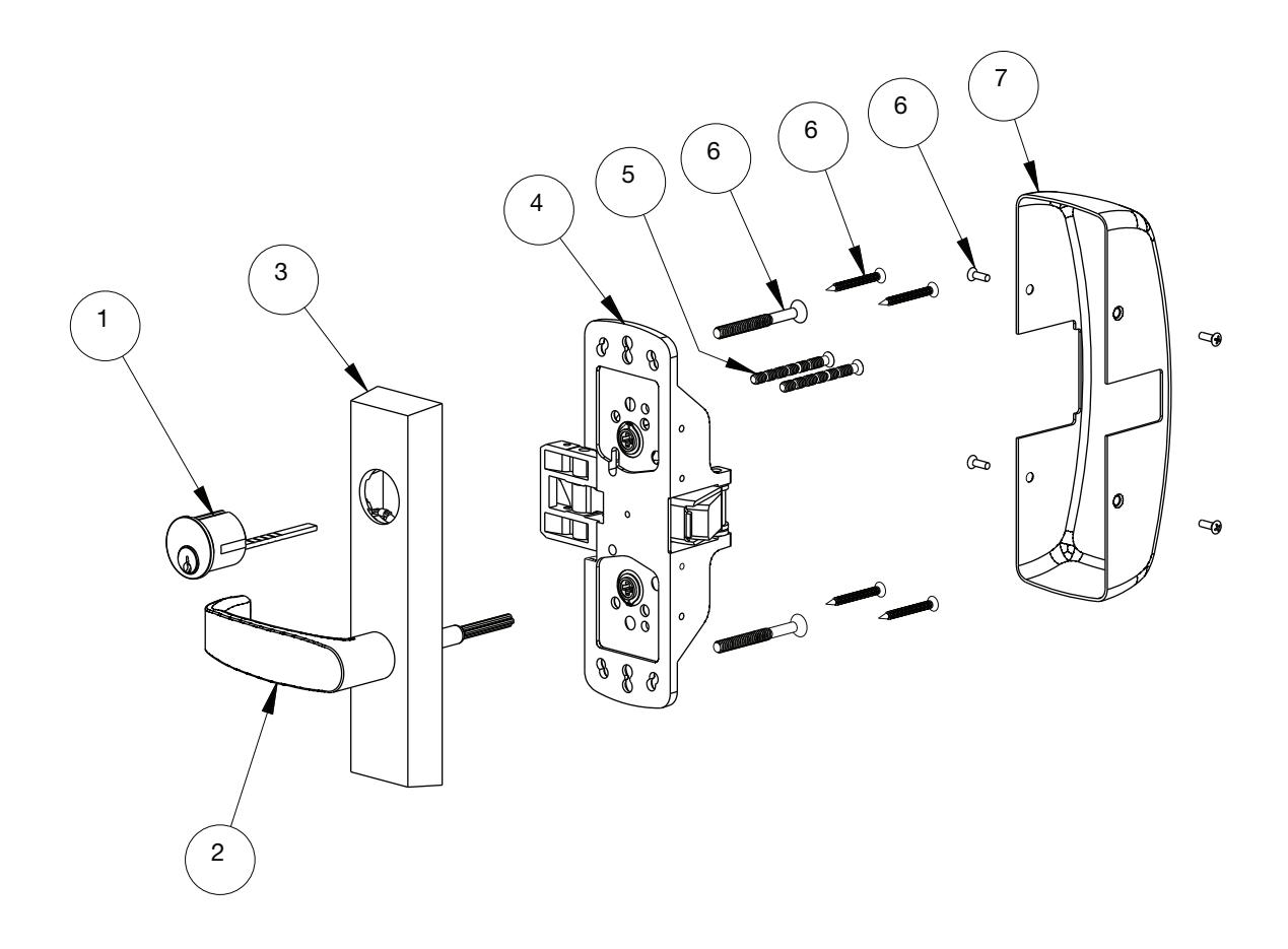
| ITEM | PART No. | DESCRIPTION | REQ'D |
|---|---|---|---|
| 1 | – | Cylinder Assembly (Reference Catalog for Available Cylinders) | 1 |
| 2 | – | Lever (Reference Catalog for Available Styles) | 1 |
| 97-4140 | Motorized Exits Trim Assembly (With Cylinder Prep) | ||
| 3 | 97-4141 | Motorized Exits Trim Assembly (Without Cylinder Prep) | 1 |
| 68-7255 | Chassis Assembly | ||
| 68-7256 | Chassis Assembly (Fire Rated) | ||
| 4 | 68-5836 | Chassis Assembly (Latch Guarding) | 1 |
| 68-5837 | Chassis Assembly (Fire Rated Latch Guarding) | ||
| 5 | 13-0074 | Cylinder Connecting Screw | 2 |
| 6 | 68-3922 | Screw Pack | 1 |
| 68-0406 | Chassis Cover (Without Latch Guarding) | ||
| 7 | 68-1014 | Chassis Cover (With Latch Guarding) | 1 |

Parts Breakdown (Continued) 8977/8978 x ET x Lever Design Passport 1000 Mortise Exit Device
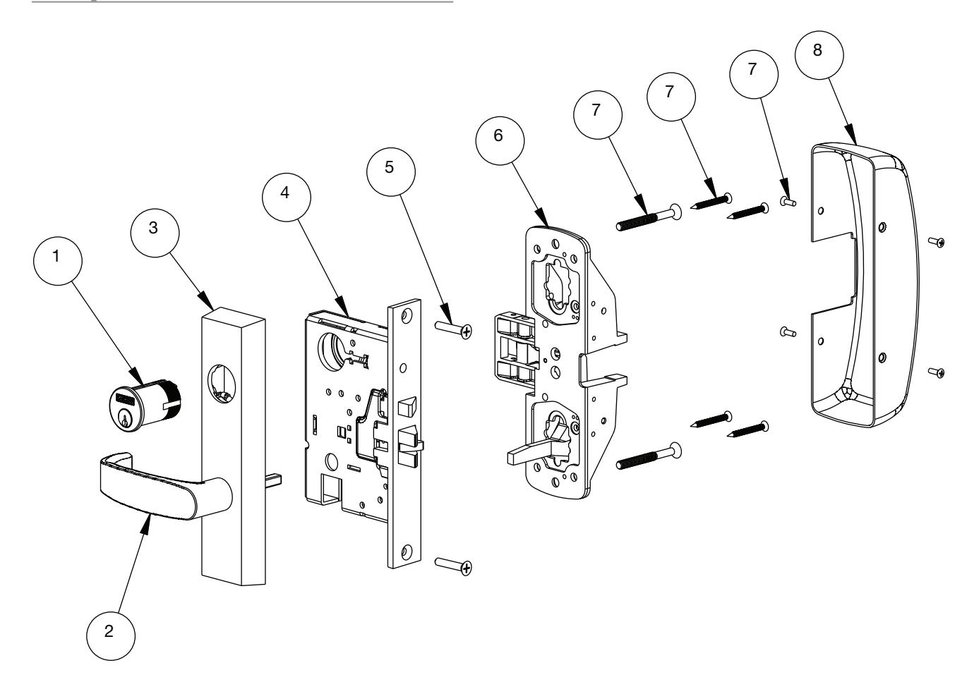
| ITEM | PART No. | DESCRIPTION | REQ'D |
|---|---|---|---|
| 1 | – | Cylinder Assembly (Reference Catalog for Available Cylinders) | 1 |
| 2 | – | Lever (Reference Catalog for Available Styles) | 1 |
| 97-4138 | Motorized Exits Trim Assembly (with Cylinder Prep) | ||
| 3 | 97-4139 | Motorized Exits Trim Assembly (without Cylinder Prep) | 1 |
| 99-2401 | 8900 Lock body Assembly LHR | ||
| 99-2402 | 8900 Lock body Assembly RHR | ||
| 4 | 99-2403 | 8900 Lock body Assembly LHR (Non-Beveled Door) | 1 |
| 99-2404 | 8900 Lock body Assembly RHR (Non-Beveled Door) | ||
| 5 | 99-2628 | Screw Pack | 1 |
| 68-7253 | Chassis Assembly LHR | ||
| 6 | 68-7254 | Chassis Assembly RHR | 1 |
| 7 | 68-2143 | Screw Pack | 1 |
| 8 | 68-0407 | Chassis Cover | 1 |
6 Installation Instructions for 8977/8978 Rim Exit
IMPORTANT: BEFORE STARTING
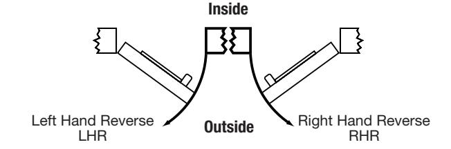
- • This device is non-handed.
- • Door should be fitted and hung.
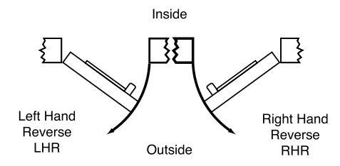
- • Verify box label for size of exit device, function and hand.
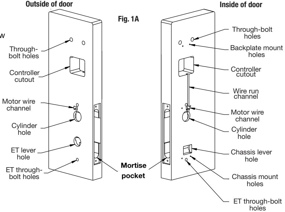
1 – Exit Hardware & Door Preparation
If using a mullion, install in frame.
Prior to installation, all holes must be free of burrs, debris and sharp edges.
If doors are not properly reinforced per ANSI 115.2, commercially available reinforcements should be installed.
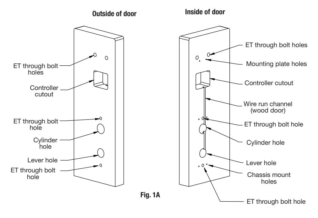
Prepare door according to appropriate template:
- Field template A7951 (or wood doors).
- Manufacturer's template 4630 (for metal doors).

Rim Installation Instructions (Continued)
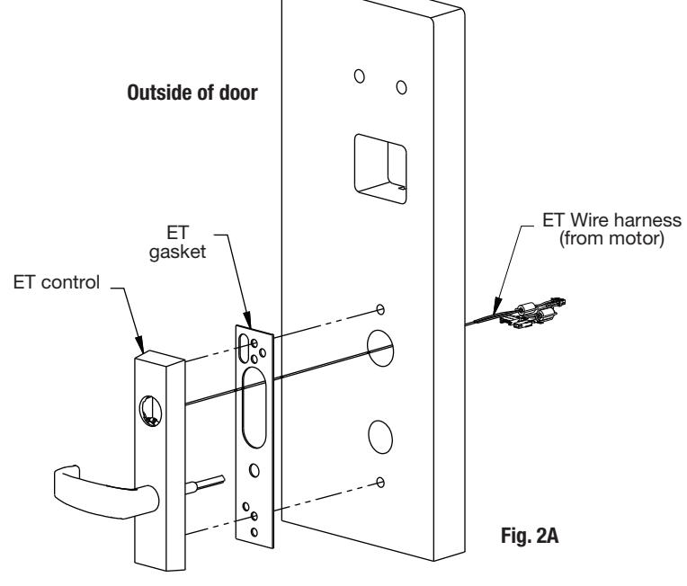
2 – Installation of Exit Trim (ET), Exit Chassis and Cylinder
A. Outside Trim
- 1. For exterior applications, "ET" gasket (52-0263) should be used to seal between "ET" escutcheon and outside door surface.
- 2. Route harness through under cut of cylinder hole and out to other side of door.
- 3. Place "ET" control onto door.
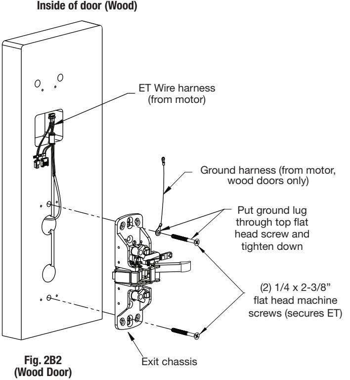
B. Inside Trim
- 1. Route "ET" harness along wire channel cutout for wood doors and access hole for metal doors.
- 2. Mount exit chassis carefully. DO NOT PINCH HARNESS WIRES.
- 3. "ET" spindle will engage into the hub of exit device chassis.
- 4. Secure chassis and "ET" with (2) 1/4 -20 x 2-3/8" flat head machine screws.
Inside of door (Metal) Fig. 2B1 ET Wire harness (from motor) Exit chassis (2) ¼ x 2-3/8" flat head machine screws (secures ET)
Outside of door Rim Installation Instructions (Continued)
2 – Installation of Exit Trim (ET), Exit Chassis and Cylinder (continued)
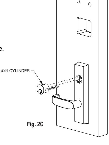
C. Cylinder Installation
Note: For devices without cylinder, go to Step 2D.
- 1. Insert cylinder into "ET" control.
- 2. Mate cylinder tailpiece into hub of exit device chassis.
- 3. Make sure "ET" harness is clear of cylinder and cylinder tailpiece.
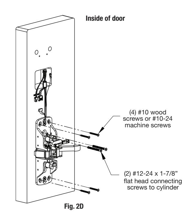
D. Securing Cylinder
- 1. Secure cylinder to exit chassis using (2) #12-24 x 1-7/8" connecting screws.
- 2. Fasten exit chassis to door using (4) #10 wood screws (for wood door) or #10-24 machine screws (for metal door).
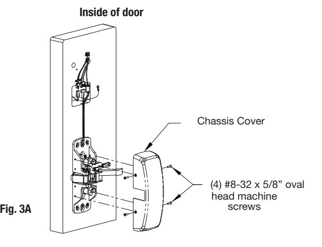
3 - Chassis Cover Instructions
Secure chassis cover to chassis using (4) #8-32 x 5/16" oval head machine screws.
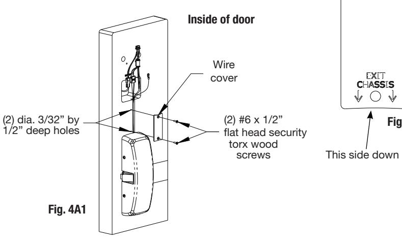
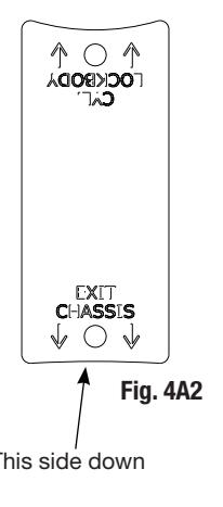
4 - Wire Cover Instructions (Wood doors only)
- 1. Align wire cover plate with chassis side against exit chassis cover and mark hole positions.
- 2. Drill (2) 3/32" diameter by 1/2" deep holes as shown (Fig. 4A1).
- 3. Ensure stamped side of plate goes against door.
- 4. Secure wire cover plate to door directly above chassis cover (note orientation) using two (2) #6 x 1/2" flat head security torx wood screws (Fig. 4A1 and 4A2).
NOTE: Position lower edge of cover plate against the chassis cover to ensure no wires are visible.
Back side of wire cover plate
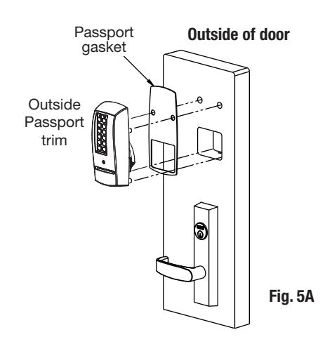
5A - Installation of Outside Escutcheon with Weatherseal Gasket (Optional)
NOTE: For non-fire rated door applications, an optional gasket may be used as a weatherseal between the escutcheon and the outside door surface. Peel off adhesive backing and attach to (outside) escutcheon (Fig. 5A).
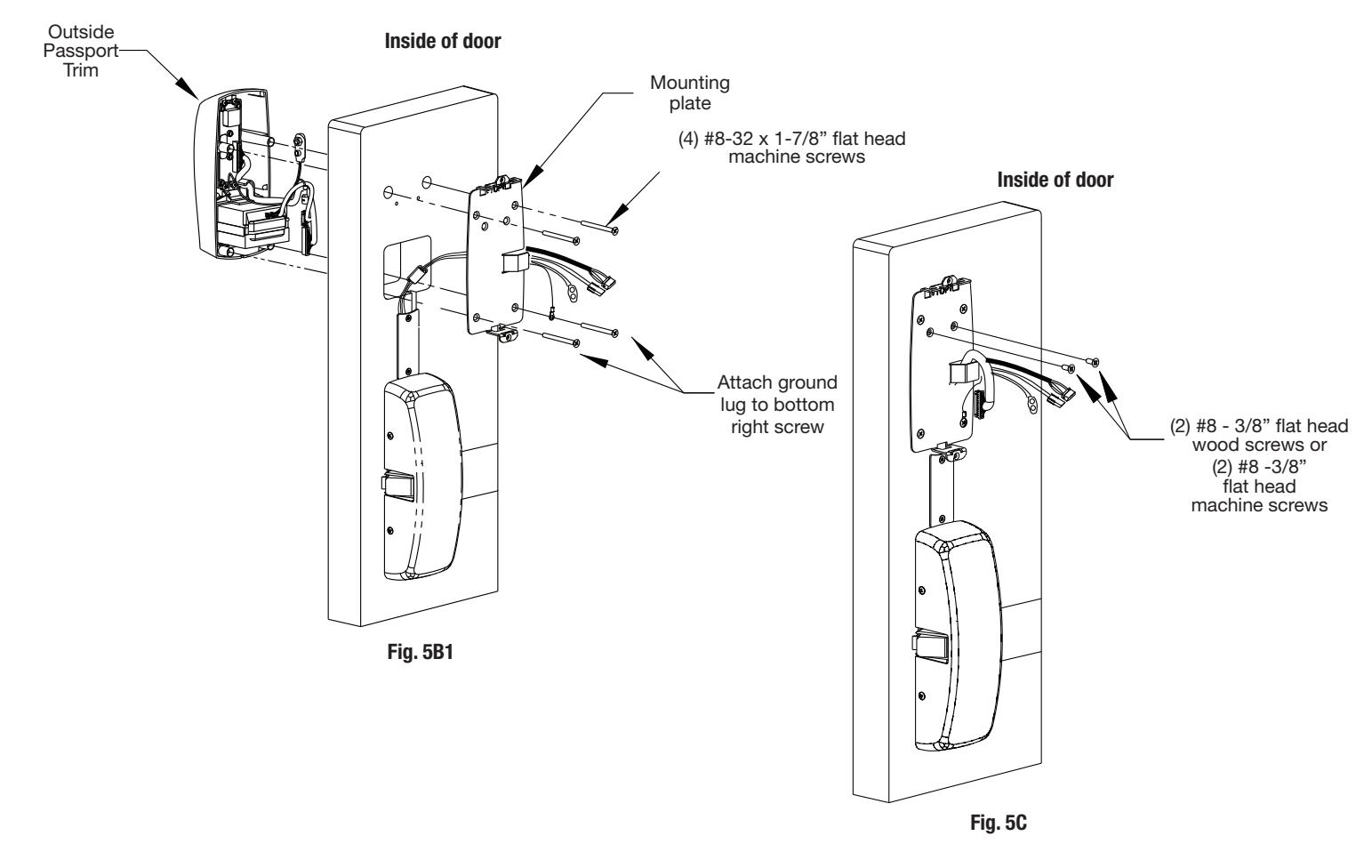
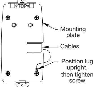
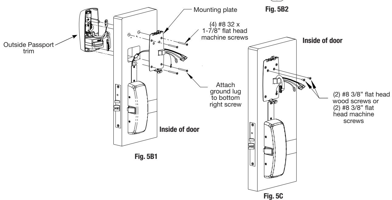
5B – Installation of Outside Escutcheon & Mounting Plate Assembly
- 1. Insert the mounting posts through holes as shown (Fig. 5B1).
- 2. On the inside of the door, position the mounting plate over the indicated holes. As you feed controller, keypad, battery and grounding cables thru side opening (Fig. 5B1), tuck the ferrite bead safely under the reader. Note: Inserting either of the top corner screws at this point will hold the plate as you feed the cables through. (Also refer to Step 6B)
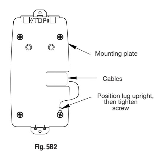
- 3. Attach grounding lug to bottom right screw and note upright positioning of lug as shown (Fig. 5B2).
- 4. Insert other corner screws and tighten all, fastening the outside escutcheon to the door (Fig. 5B1).
IMPORTANT If the following step is skipped, the product will not be UL-compliant:
5. Attach two (2) #8 x 3/8" flat head wood screws for wood doors, or (2) #8-32 x 3/8" flat head machine screws for metal doors (Fig. 5C). Tighten securely.
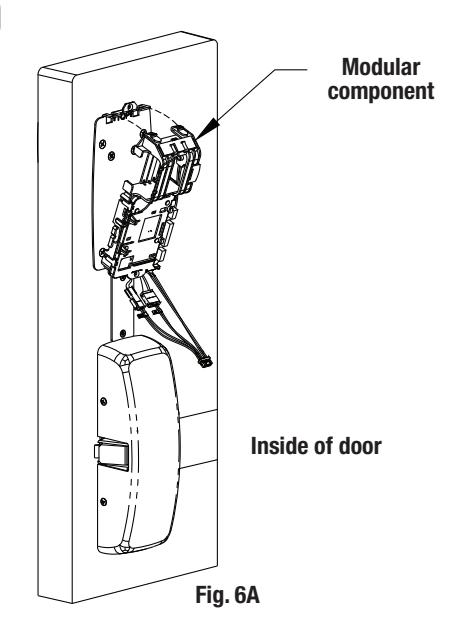
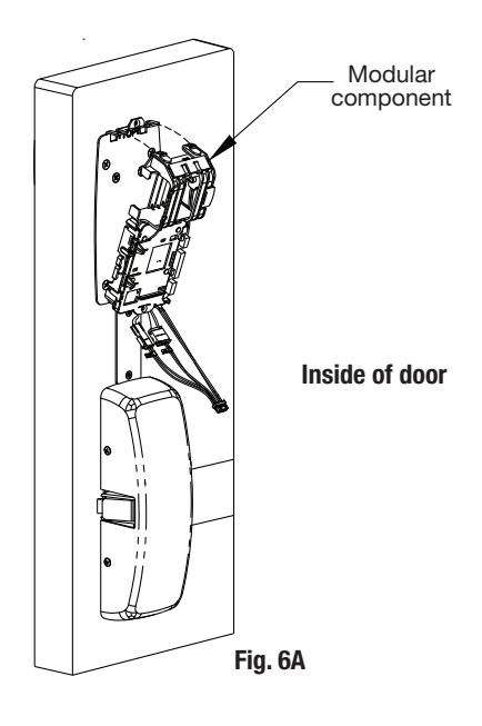
6A – Installation of Inside Component Assembly
- 1. Insert bottom of component assembly first (Fig. 6A).
- 2. Clip top of component assembly to mounting plate verifying both tabs attached securely.
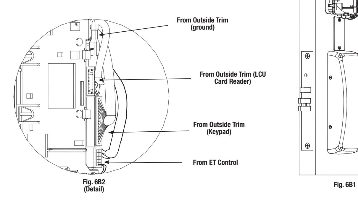
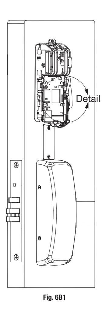
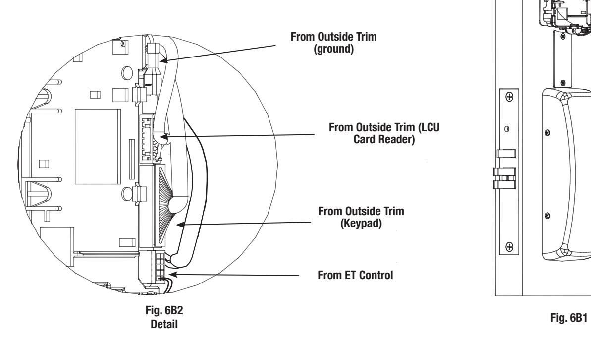
6B - Installation of Connectors
Secure the following connectors onto the circuit board (Fig. 6B1 and 6B2):
- 1. Secure the mortise lock body assembly connector (10-pin).
- 2. Secure the mortise keypad/card reader connector (14-pin).
- 3. Secure the LCU connector (7-pin).
NOTE:
- Connectors go on only one way.
- Do not force and do not offset connectors.
- Be sure they are completely seated (flush).
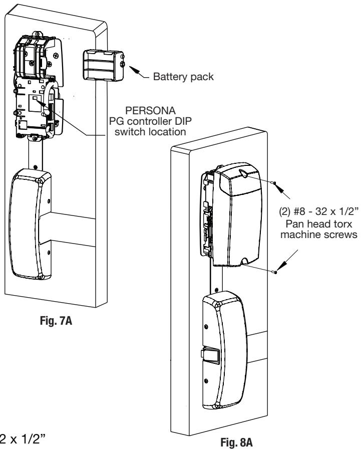
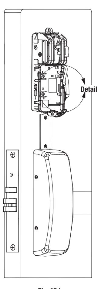
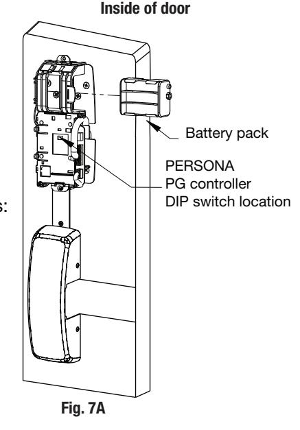
7 - Battery/Battery Pack Installation
- 1. Place (6) "AA" batteries into the compartment being careful to align polarity (- & +) according to case markings.
- 2. Insert battery pack and click into place, making sure polarity terminals on the battery pack are oriented upward (Fig. 7A).
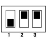
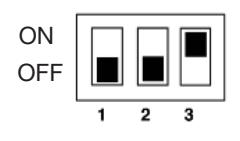
- 3. Verify DIP switch settings are correct for the application.
PERSONA PG Controller DIP Switch Settings (Fig 7A):
SARGENT mortise lock with and without deadbolt:
- Switch 1 and 2 OFF
- Switch 3 ON
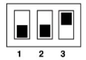
SARGENT cylinder or exit locks:
- Switch 1 OFF
- Switch 2 and 3 ON

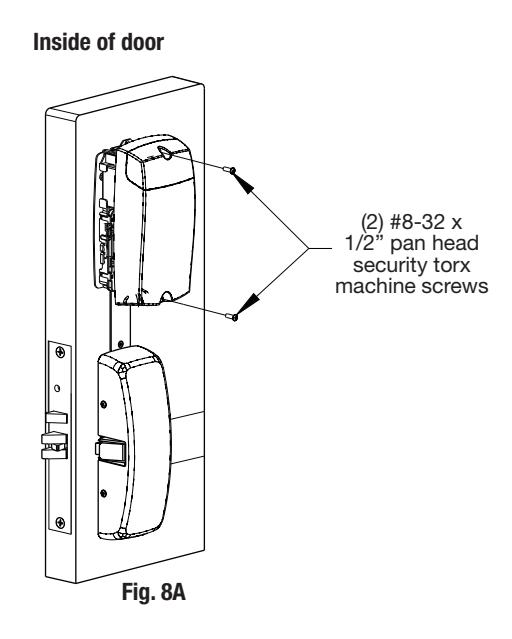
1. Position inside escutcheon (Fig. 8A). Secure with two (2) #8-32 x 1/2" pan head security torx (tool provided) machine head screws.
Note: All wires should be placed inside to avoid being pinched.
2. Straighten escutcheon and tighten securely.

7 Installation Instructions for Mortise Type Exit Device 8977/8978
IMPORTANT BEFORE STARTING:
- • This device is non-handed.
- • Door should be fitted and hung.
- • Verify box label for size of exit device, function and hand.
1 – Exit Hardware and Door Preparation
If using a mullion, install in frame.
Prior to installation, all holes must be free of burrs, debris and sharp edges.
If doors are not properly reinforced per ANSI 115.2, commercially available reinforcements should be installed.
Prepare door according to exit installation instructions A6705 and appropriate template:
- Field templates A7460 and A7461 (for wood doors).
- Manufacturer's templates 4537 and 4538 (for metal doors).
NOTE: Instruction examples show wood door installation. For metal doors, route cables inside door.
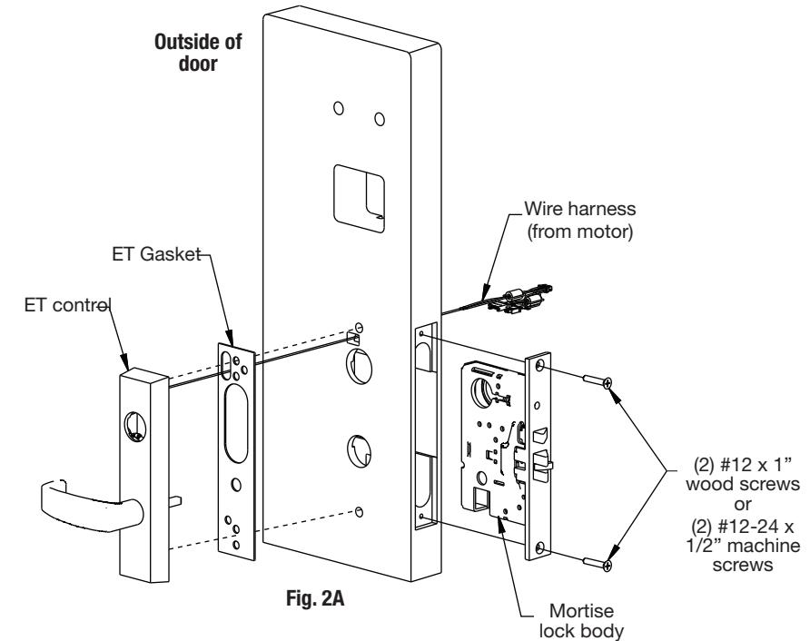
2 – Installation of Outside Exit Trim (ET), Exit Chassis and Cylinder
A. Outside Trim
- 1. Slide mortise lock into door and securely fasten with (2) flat head screws.
- 2. For exterior applications, gasket (52-0263) should be used to seal between "ET" escutcheon and outside door surface.
- 3. Route "ET" harness through wire cutout and out other side of door.
- 4. Place "ET" control on door with spindle inserted through mortise lock.
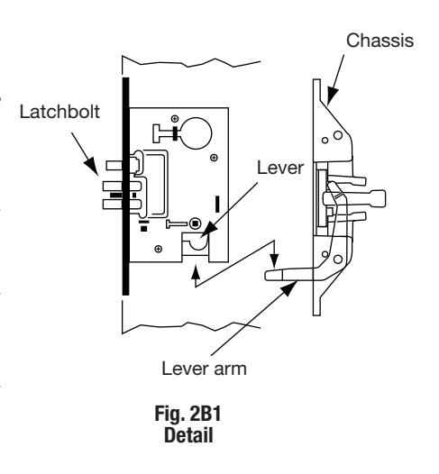
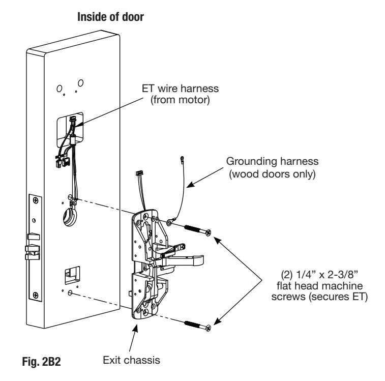
B. Exit Chassis:
- 1. Route "ET" harness along track cutout for wood doors and access hole for metal doors.
- 2. Mount exit chassis carefully. Do not pinch harness wires.
- 3. Position exit chassis on door with lever arm under rear section of mortise lock.
- 4. Using (2) 1/4-20 x 2-3/8" flat head screws, attach chassis to "ET" control.
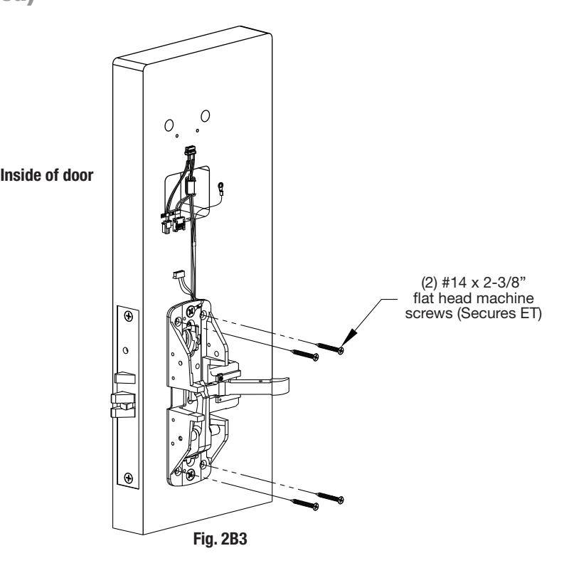
2 – Installation of Outside Trim, Exit Chassis and Cylinder (Continued)
B. Exit Chassis (Continued):
Fasten exit chassis to door using (4) #10 wood screws or #10-24 machine screws (Fig. 2B3).
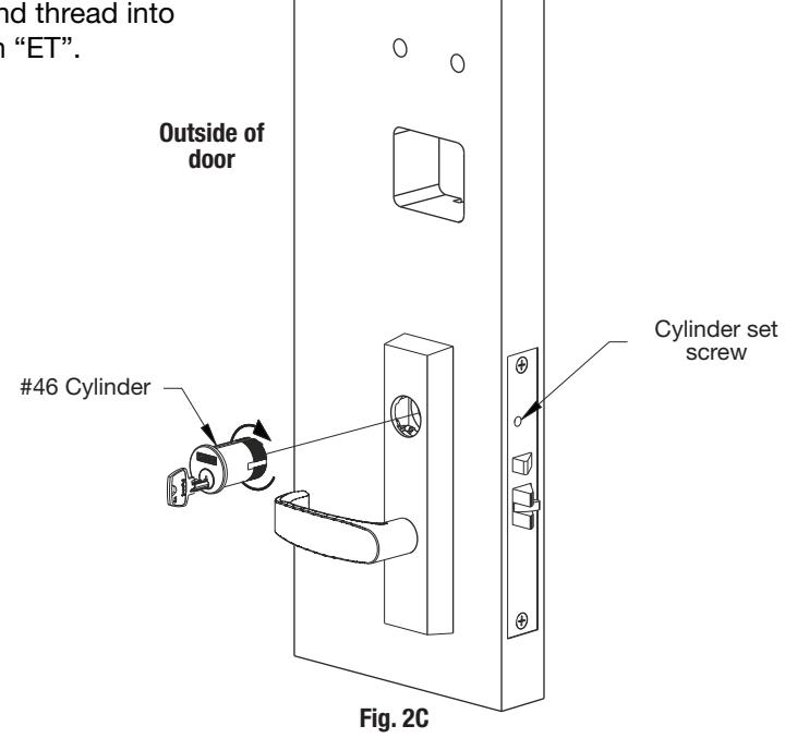
C. Cylinder Installation
Note: For devices without cylinders, skip this section.
- 1. Back cylinder set screw out of mortise lock.
- 2. Insert cylinder through "ET" control and thread into mortise lock until cylinder is flush with "ET".
- 3. Tighten cylinder set screw.
01/31/18
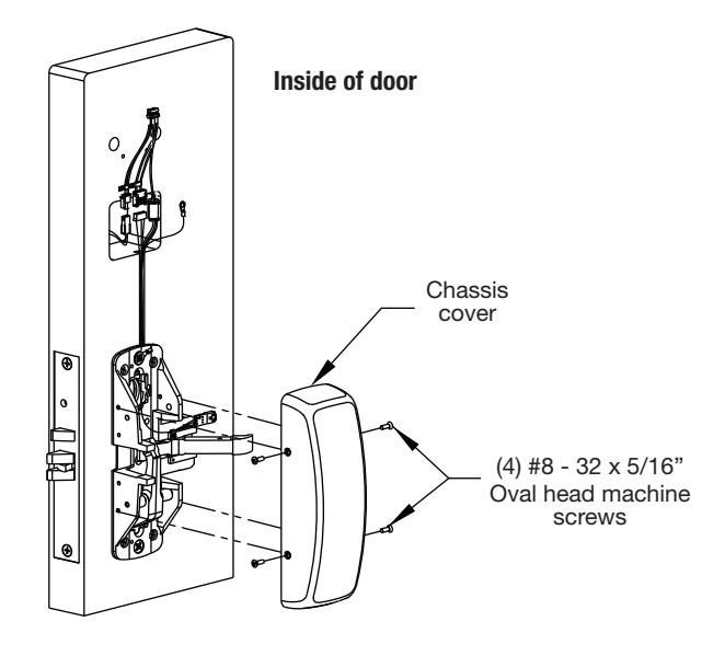
3 – Chassis Cover Instructions
Secure chassis cover to chassis using (4) #8 - 32 x 5/16" oval head machine screws.
Back side of wire cover plate
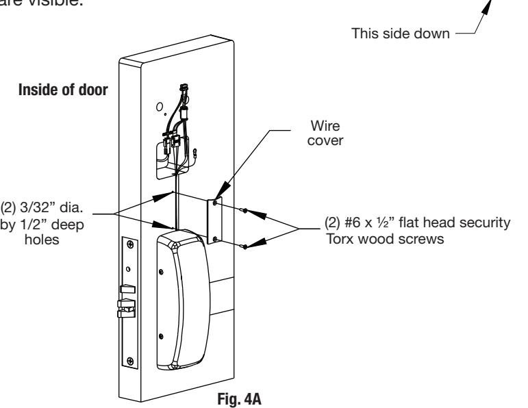
4 - Wire Cover Instructions (Wood Door Only)
Note: Required for 12- Fire Rated doors only.
- 1. Align wire cover plate with chassis side against exit chassis cover and mark hole positions.
- 2. Drill (2) 3/32" dia. by 1/2" deep holes as shown.
- 3. Stamped side of plate goes against door.
- 4. Secure wire cover plate to door directly above chassis cover (note orientation) using two (2) #6 x 1/2" flat head security torx wood screws.
Note: Position lower edge of cover plate against the chassis cover to ensure no wires are visible.
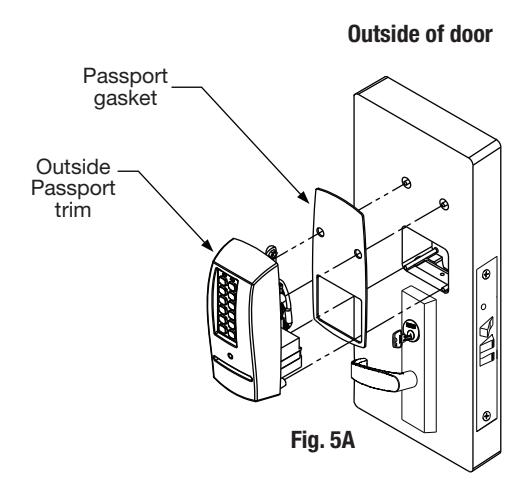
5A – Installation of Outside Escutcheon with Weatherseal Gasket (optional)
Note: For non-fire rated door applications, an optional gasket may be used as a weatherseal between the escutcheon and the outside door surface. Peel off adhesive backing and attach to (outside) escutcheon (Fig. 5A).
5B – Installation of Outside Escutcheon & Mounting Plate Assembly
- 1. Insert the mounting posts through holes as shown (Fig.5B1).
- 2. On the inside of the door, position the mounting plate over the indicated holes. As you feed controller, keypad, battery and grounding cables through the side opening (Fig.5B1), tuck the ferrite bead carefully under the reader. Note: Insert either of the top corner screws to hold the plate as you feed the cables through. Also refer to Step 6B.
- 3. Attach grounding lug to bottom right screw. Position upright as shown (Fig.5B2).
- 4. Insert remaining corner screws and tighten all, fastening the outside escutcheon to the door (Fig.5B1).
- 5. IMPORTANT: If the following step is skipped, the product will not be UL-compliant:
Attach two (2) #8 x 3/8" flat head wood screws for wood doors, or (2) #8-32 x 3/8" flat head machine screws for metal doors (Fig.5C).
Tighten securely.
6A – Installation of Inside Component Assembly
- 1. Insert bottom of component assembly first (Fig. 6A).
- 2. Clip top of component assembly to mounting plate verifying both tabs attached securely.
6B - Installation of Connectors
Secure the following connectors onto the circuit board (Fig. 6B1 and 6B2):
- 1. Secure the mortise lock body assembly connector (10-pin).
- 2. Secure the mortise keypad/card reader connector (14-pin).
- 3. Secure the LCU connector (7-pin).
NOTES:
- Connectors go on only one way.
- Do not force and do not offset connectors.
- Be sure they are completely seated (flush).
7 - Battery/Battery Pack Installation and DIP Switch Verification
- 1. Place (6) "AA" batteries into the compartment, being careful to properly align polarity (- & +) .
- 2. Insert battery pack and click into place making sure polarity terminals on the battery pack are oriented upward as in Fig. 7A.
- 3. Verify DIP switch settings are correct for the application.
PERSONA PG Controller DIP Switch Settings (Fig 7A):
ON OFF
SARGENT mortise lock with and without deadbolt:
- Switch 1 and 2 OFF
- Switch 3 ON
SARGENT cylinder or exit locks:
- Switch 1 OFF
- Switch 2 and 3 ON
8 - Installation of Inside Escutcheon
-
1. Position inside escutcheon (Fig. 8A); insert screws top and bottom and tighten securely. Do not over tighten.
- Note: All wires should be placed inside to avoid being pinched.
- 2. Straighten escutcheon and tighten securely.

Setting up the Locklink™ and Contact Card for First Use* 8
*NOTE: The following steps in this section are only performed one time. Once Bluetooth pairing is complete, these steps do not need to be repeated to program locks (Section 8 "Lockset Programming").
Pairing the Pocket PC with the Contact Card
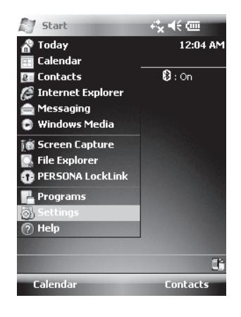
1.To begin, highlight (by tapping) the button and select the 'Settings' menu.
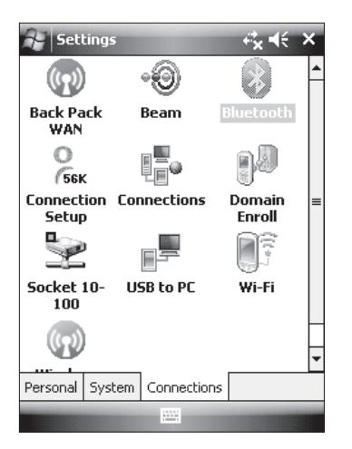
2. Next, tap the 'Connections' tab at the bottom of the screen and highlight the Bluetooth icon from the 'Settings' menu.
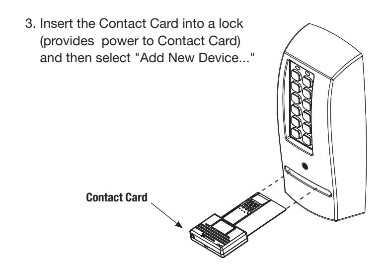
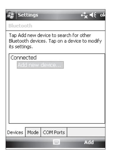
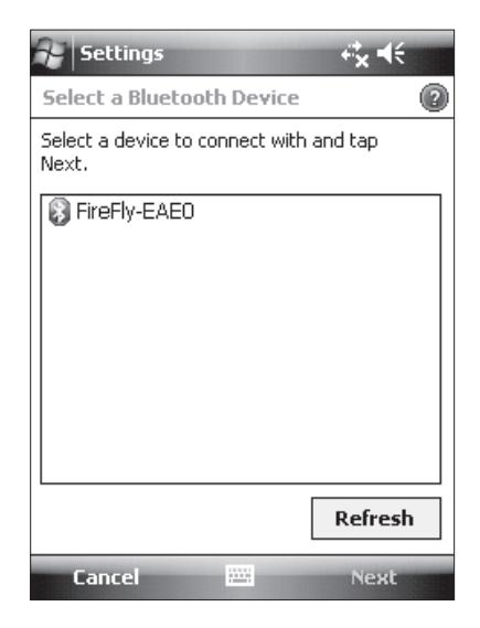
4. The Pocket PC will enable Bluetooth and begin discovery. If you receive a warning, "No Devices Found," then check again to see the blue light flashing on the contact card and tap 'Retry' .
If the blue light is not flashing, remove the contact card, wait for the lights to go dark, then reinsert it before tapping 'Retry'.
If this step fails repeatedly, then contact PERSONA technical support at (800)–481–8464.
Configuring the Locklink Software
Once you can see the " " list entry, highlight it and tap 'Next'.
- 1. Enter "1234" when prompted for 'Passcode'.
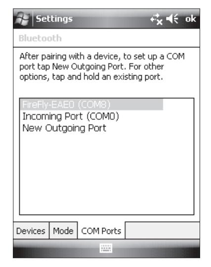
- 2. Tap the 'COM Ports' tab at the bottom of the screen.
Note the COM port number assigned to the Firefly device.
NOTE: If you do not see the FireFly-EAE0 device in the COM port list, tap "New Outgoing Port" and pick the FireFly-EAE0 device before tapping "Next."
3. Choose an available COM port number (COM8 is often a good choice) and tap "Finish."
9 Lockset Programming
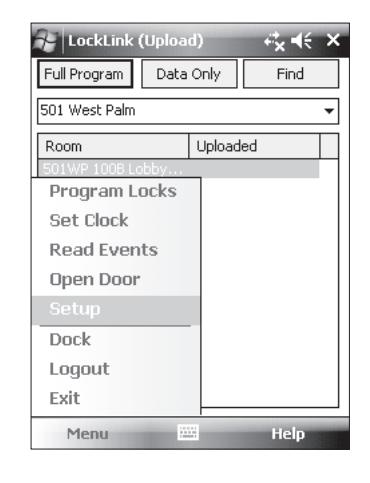
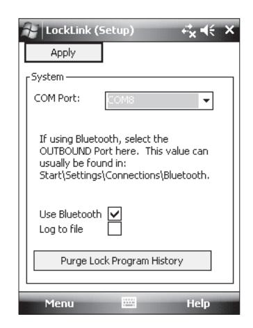
- 1. Tap then tap to launch the LockLink program. Choose Menu and then 'Setup'.
- 2. Pick the COM port noted in Step 6. Check the box 'Use Bluetooth' and click 'Apply'.
Start the PERSONA LockLink™ software:
- 1. Tap the Start button on the Pocket PC Screen.
-
2. If visible, select PERSONA LockLink™ to launch the program; otherwise, tap Start and Programs to launch the Programs list and then select the PERSONA LockLink™ icon (right).
- 3. Log into the LockLink™ by tapping the arrow and selecting your username from the drop down list:
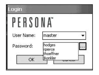
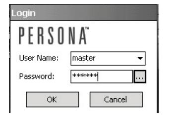
4. Type in your password.
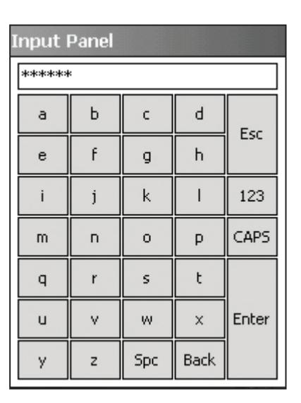
You can use the onscreen keyboard entry method to enter information.
5. To access the full screen keyboard (shown at right) tap on the ellipsis (three dots) next to the password field.
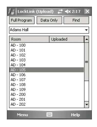
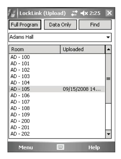
Once you have entered your password, you will begin on the Upload screen. This is the proper place to be for programming locks.
Note: Be sure to perform an Operational Check (see Section 9) for each lock.
Lockset Programming Instructions (Continued)
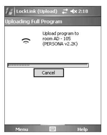
Upload Full Program
After locks are installed, they must have program files copied into them before they can receive and interpret data. In many ways, the program files act as the locks' operating system by interpreting the lock data to control each lock's behavior.
1. Highlight (by tapping) the name of the lock that you wish to program.
If the list of locks is longer than the display, locate the lock using the scroll bar at the right of the display or use the button at the top of the display.
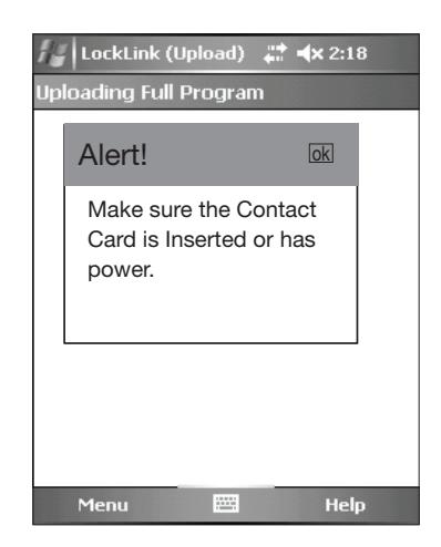
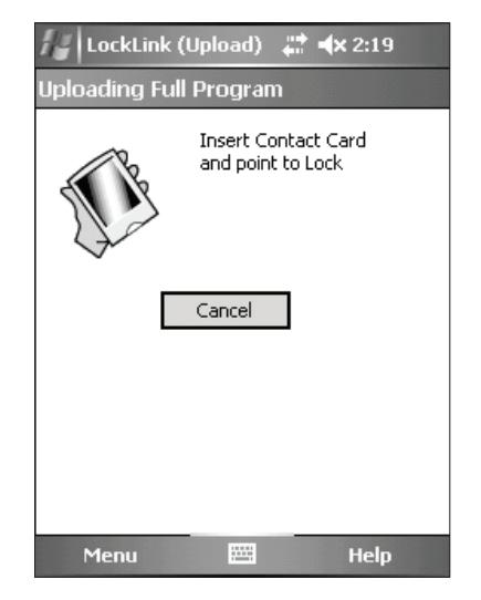
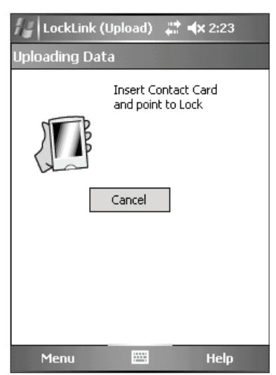
- 2. Tap the button to completely initialize the lock; the message "Alert! Make sure the Contact Card is Inserted or has power."
- 3. Tap "ok".
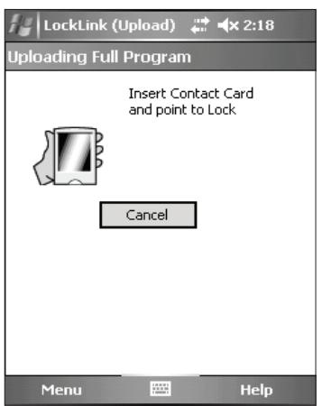
- 4. Follow the directions on the screen.
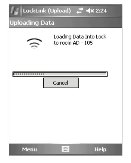
NOTE: You will be prompted to insert the Contact Card into the lock three times.
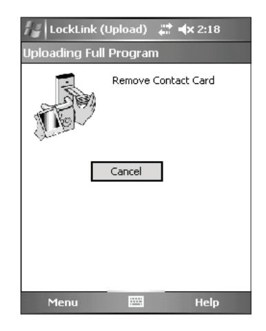
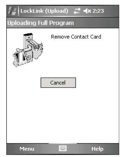
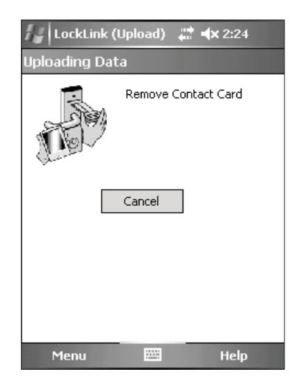
5. When the data has finished loading, you are notified to remove the Contact Card from the lock.

Lockset Programming Instructions (Continued)
6. Reinsert Contact Card a second time to initialize the program.
Note: You should hear the motor run briefly.
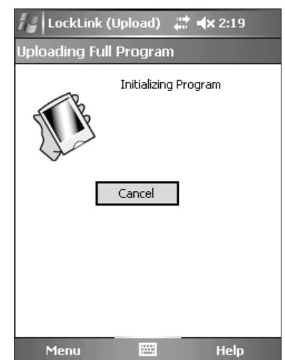
7. Program initializes and directs you to remove the Contact Card.
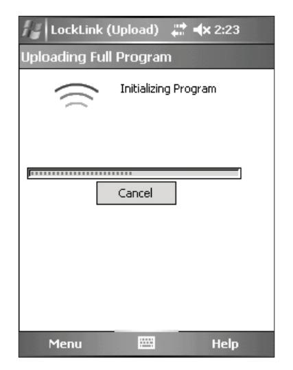
8. Follow the on-screen directions and reinsert the Contact Card a third time.
Lockset Programming Instructions (Continued)
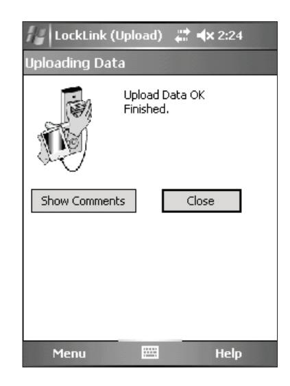
- 9. Remove the Contact Card.
- 10. To exit and return to the program screen, tap the button.
- 11. After programming the new lockset, verify operation by performing the Operational Check (refer to Section 9).
-
12. Repeat this procedure for each lock to be programmed with lock data.
- NOTE: With a successful upload, the time and date that the lock was programmed will appear beside each lock name.

10 Operational Check
IMPORTANT: Be sure to test functions prior to closing door.
In all cases, perform the following checks:
- 1. Ensure that inside lever retracts latch (and deadbolt for deadbolt functions).
- For devices with cylinders, the following checks apply:
Insert key into cylinder and rotate:
- a. There should be no friction against lock case, wire harness, or any other obstructions.
- If harness friction exists, refer to the section on 'Installation of Inside Component Assembly' in PERSONA instructions A7809 (this manual).
- b. The key should retract the latch and the key should rotate freely.
- c. The key should extend and retract the latchbolt.
- For units without a keypad, the following checks apply:
Insert test card marked NO PIN and retract:
- a. Ensure lockset displays a green flash (and no other lights).
- b. Ensure outside lever retracts latch, the door opens, and that there is no binding against lock case, wire harness or other obstructions.
- For units with a keypad, test the keypad by using the following checks:
Create and insert a test card marked 'PIN 1234' and retract:
- a. Ensure lockset displays solid yellow light.
- b. Type 1, 2, 3, 4 on keypad.
- c. Ensure outside lever retracts latch, the door opens, and that there is no binding against lock case, wire harness or other obstructions.
- d. Test again with card marked 'PIN 5678'.
- e. Test again with card marked 'PIN 9090'.
- 2. Any rapid yellow or rapid red flashing lights indicate a low power condition. Check the battery voltage at the top of the battery pack to check for the required 9V. If the voltage is correct, inspect the wiring for a possible short.
- 3. When you have completed the tests, close the door, ensuring latchbolt and deadbolt fully extend into strike plate without binding.
01/31/18

Sargent Manufacturing Company 100 Sargent Drive New Haven, CT 06511 USA PERSONA Technical Support: 800-481-8464 • www.personacampus.com
Founded in the early 1800s, SARGENT® is a market leader in locksets, cylinders, door closers, exit devices, electro-mechanical products and access control systems for new construction, renovation, and replacement applications. The company's customer base includes commercial construction, institutional, and industrial markets.
Copyright © 2018, Sargent Manufacturing Company, an ASSA ABLOY Group company. All rights reserved. Reproduction in whole or in part without the express written permission of Sargent Manufacturing Company is prohibited.