PDQ 6W199 Installation Instruction- 639412 R0
Open the original PDF document
View PDF6W199 Electrified Exit Device Trim INSTALLATION INSTRUCTIONS

Phone: 833-2-PDQTEC | www.pdqlocks.com
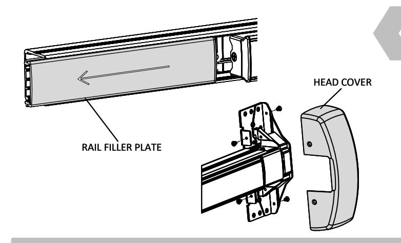
1. REMOVE HEAD COVER AND RAIL FILLER PLATE
• Remove (4) screws, push latch into device to remove head cover
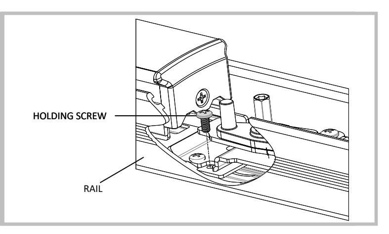
2. REMOVE HOLDING SCREW AND RAIL
- Remove screw securing backplate to rail
- Remove backplate from rail
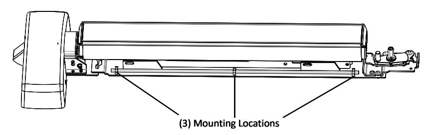

3. INSTALL WIRE SADDLES ONTO BACKPLATE
• Secure (3) wire saddles to backplate
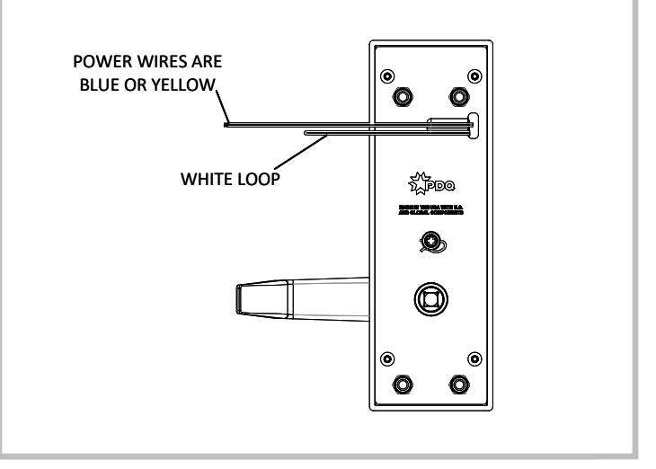
4. CONFIGURE TRIM FOR FAIL SAFE OR FAIL SECURE
-
Fail Secure
: Power to Unlock (Default)
- Outside trim is locked when power is OFF, and unlocked when power is ON
-
Fail Safe
: Power to Lock (Cut White Loop)
- Outside trim is locked when power is ON, and unlocked when power is OFF.
6W199 Electrified Exit Device Trim INSTALLATION INSTRUCTIONS

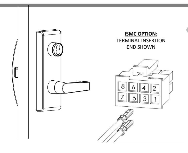
5. INSTALL TRIM AND DEVICE
- Refer to trim and exit device installation instructions and templates.
-
For ISMC option only:
- Install nonpolar blue or yellow power wires into positions 1 & 2 on housing
- If REX and/or LM option is selected, install wires in existing housing on exit device. Otherwise, install wires in provided 8-pin housing
ELECTRICAL SPECIFICATIONS
Keep operating voltage at +/- 10% of rated voltage
| Vin | Max Inrush Current | Standby Current |
|---|---|---|
| 12-24 VDC | 1.0A | 5mA |
| 12-24 VAC | 1.0A | 15mA |
Important Notes :
Power must be applied to lock for a minimum of 5 seconds. It may be necessary to adjust the default time delay on your system. Device may not lock reliably if powered for less than 5 seconds
To convert from fail secure to fail safe, cut the white wire loop. No need to cover the cut wires. To revert to fail secure, reconnect the white wires with a suitable wire nut for two 24AWG wires.
Kit includes components to safely route wires through 6300/6400 exit device. Failure to use this kit will result in pinched wires.