PDQ 6300M or 6300MF Device Installation Instruction – 639415 R0
Open the original PDF document
View PDF6300M/MF EXIT INSTALLATION INSTRUCTION MORTISE DEVICE

Phone: 833-2-PDQTEC | www.pdqlocks.com
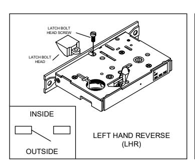
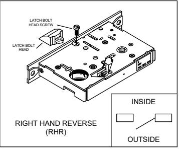

1. MORTISE HANDING
- To re-hand mortise case, remove latch bolt screw as shown.
- Orient the latch bolt head to match handing.
- Reinsert and tighten the latch bolt screw.
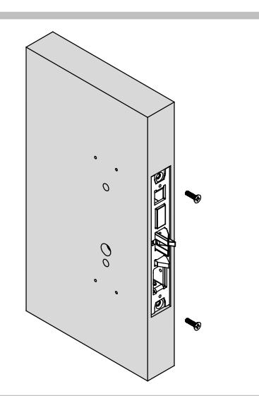
2. DOOR PREPARATION
- Prepare the door for the mortise lock using the 6300M/MF template in box.
- · Refer to trim template if installing trim.
- Install the mortise case and secure using two (2) #12-24 combo screws supplied in the hardware kit.
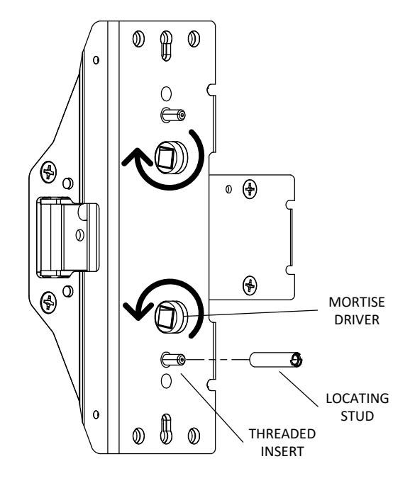

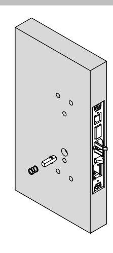
3. PREPARE DEVICE
- Install locating stud on lower threaded insert as determined by handing.
- Rotate lower mortise driver as shown until it stops. Make sure when installing that mortise driver remains in this position.
6300M/MF EXIT INSTALLATION INSTRUCTION MORTISE DEVICE

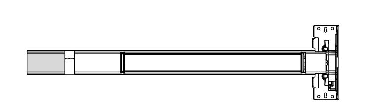
4. SIZE DEVICE
- Standard lengths are for 36" or 48" door. Device must be cut for other lengths.
- Mark length with tape length equals device size minus desired door size (for 30" door = cut 6" off 36" device) ensuring a square cut.
| Maximum cut off length: | |||||
|---|---|---|---|---|---|
| Panic | Fire | Alarm | MLR | ||
| 36" Device | 6" | 8" | 2" | 3" | |
| 48" Device | 12" | 14" | 8" | 9" | |

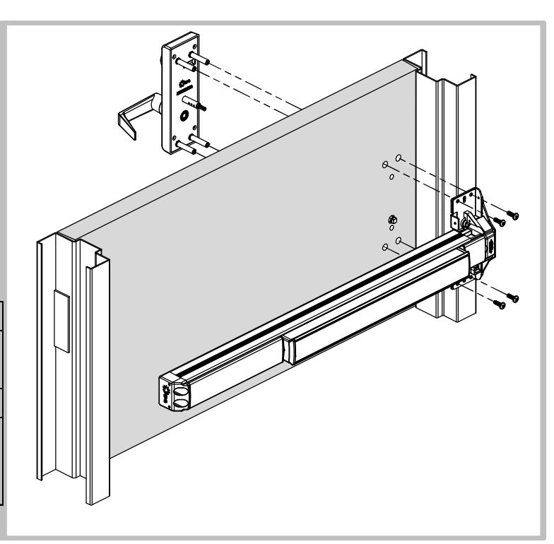
5. INSTALL DEVICE SPINDLE
Install spindle and spring in orientation shown on push side of door.
6. INSTALL DEVICE
- Install device and trim with 1/4-20 screws from the hardware kit.
- Device can be surface mounted to the door, optional sex nuts are available, device is through bolted when using trim.
| Mounting Options: | |||
|---|---|---|---|
| Surface Mount: Drill/Tap push | |||
| or Aluminum Door | side for 1/4-20 | ||
| Solid Wood Door | Drill 1/8" Pilot Hole for #10 Wood | ||
| All Others | Use optional Sex Bolts. Drill push | ||
| side with 9/32" drill bit. Drill pull | |||
| side with 3/8" drill bit. | |||
6300M/MF EXIT INSTALLATION INSTRUCTION MORTISE DEVICE

Phone: 833-2-PDQTEC | www.pdqlocks.com
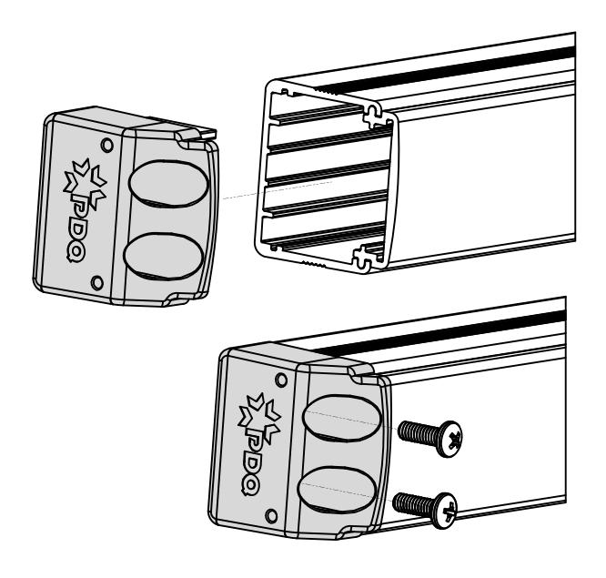

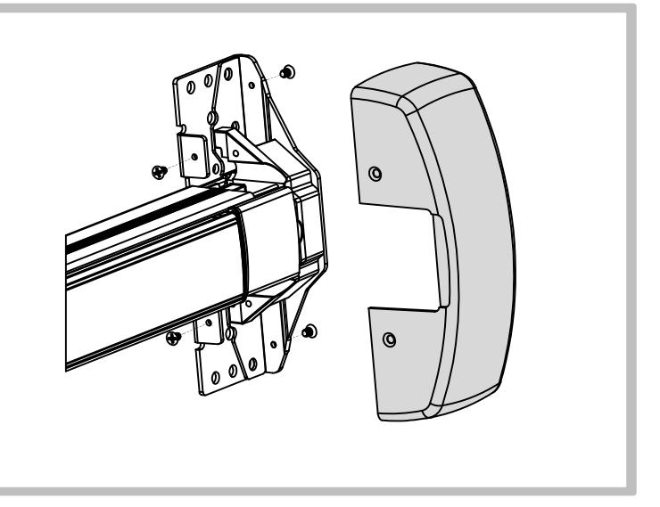
7. INSTALL END CAP
- Slide end cap into rail. Ensure rail is level. Mark the centers of the slots.
- Remove end cap then drill holes using the chart from Step 3.
- Reinstall end cap and fasten with screws.
8. INSTALL HEAD COVER
- Slide head cover onto exit device
- Install 4 mounting screws
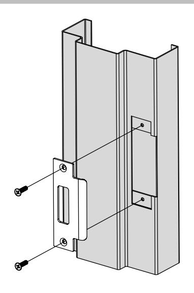

9. INSTALL STRIKE
Install the strike and secure with two (2) #12-24 combo screws supplied in the strike screw pack.