PDQ 6300 PDQ 6400 MLR Instruction – 639408 R0
Open the original PDF document
View PDF63/6400 MOTORIZED LATCH RETRACTION (MLR)
CALIBRATION AND INSTALLATION INSTRUCTIONS

Phone: 833-2-PDQTEC | www.pdqlocks.com
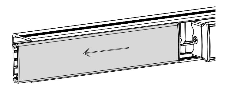
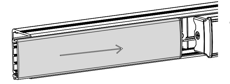
1. REMOVE FILLER PLATE
- Slide filler plate away from pushbar
- If plastic filler plug remains inside main rail, remove and reinstall into filler plate
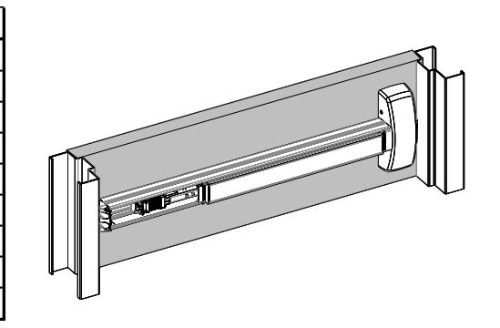
2. INSTALL EXIT DEVICE THEN CONNECT POWER
- Follow exit device template and instructions to fully install exit device without filler plate
- Terminate all MLR connections
* Refer to pdqlocks.com for MLR datasheet
| 63/6400 Pinout | |
|---|---|
| Function | Color |
| MLR | Black |
| MLR | Black |
| REX (COM) | Yellow |
| REX (N/O) | Red |
| REX (N/C) | Gray |
| LM (COM) | Black |
| LM (N/O) | Brown |
| LM (N/C) | Blue |
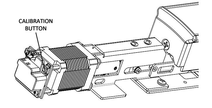
3. ENTER CALIBRATION MODE
- Press and hold calibration button
-
Apply momentary power
- o i.e. swipe badge or enter pin
- The unit will emit (1) short beep
- Release calibration button
- The device is now in calibration mode
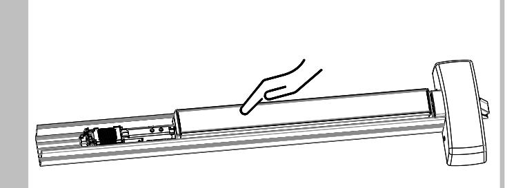
4. CALIBRATE PUSHBAR
- Depress pushbar then apply momentary power
- The device will emit (1) long beep
- When beep has finished, release pushbar
- Test latch retraction with badge/pin
*If calibration is not to your liking, repeat steps 3 and 4


5. REINSTALL FILLER PLATE AND END CAP
- Ensure filler plate is flush with main rail
- Reinstall end cap
MLR FIELD INSTALLAITON INSTRUCTION
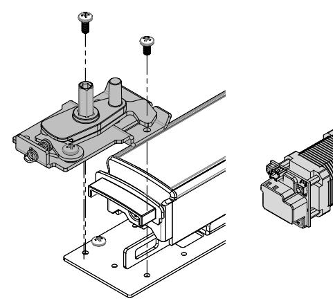
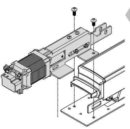
1. REMOVE EXISTING DOGGING PLATE AND REPLACE WITH MLR
- Remove (3) screws that are securing dogging plate, if applicable
- Discard dogging plate
- Install MLR
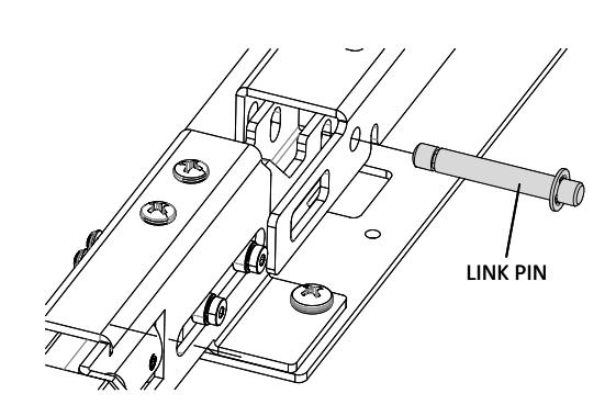
2. INSTALL LINK ROD
- Install link rod through link bar and through MLR bracket
- Install retaining ring on both sides
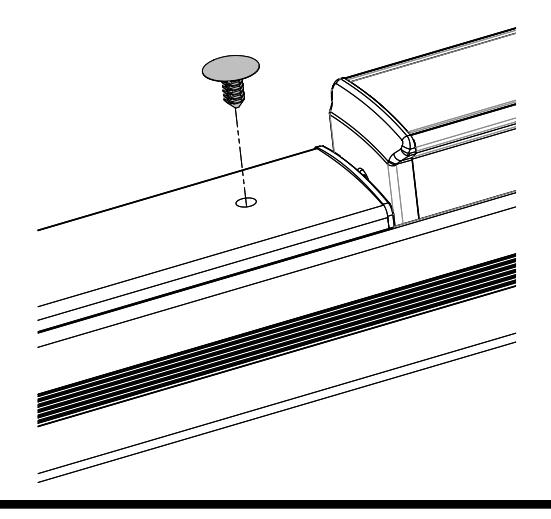

3. INSTALL PUSH-IN RIVET INTO FILLER PLATE
• Consult customer service if you are converting from anything other than hex dogging