PD25-MREXKIT-ED Installation Instruction
Open the original PDF document
View PDF

PD25REXKIT-ED
INSTALLATION INSTRUCTIONS
The PD25REXKIT-ED is a field installable request to exit kit (SPDT) for PD25/26 & Cal Royal 7700 series exit devices.
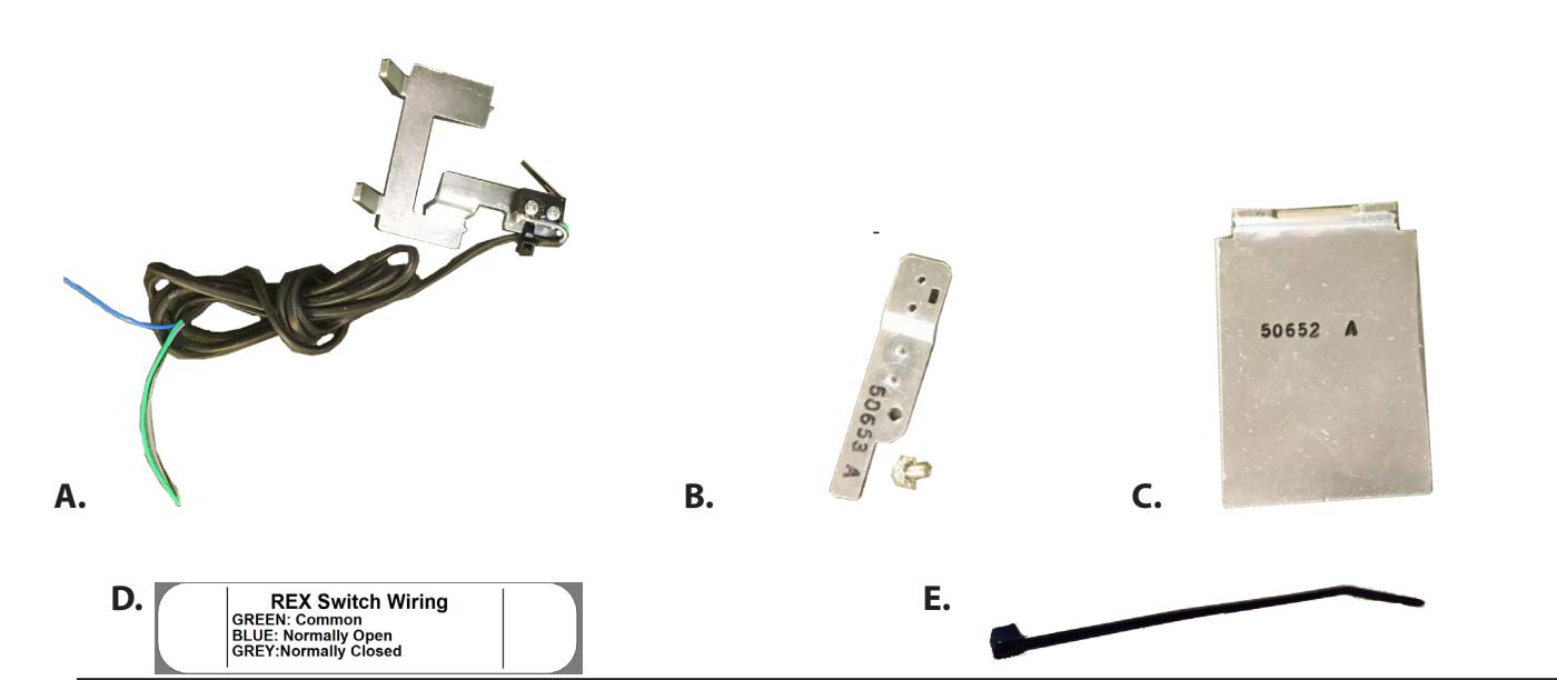
PD25REXKIT-ED In c l ude s
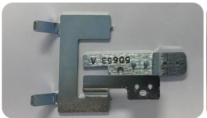
- A. REX Switch
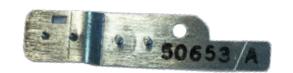
- B. REX Extension
- C. REX 48" Spacer
- D. REX Label
- E. Zip tie
S peci f ic atio n s • Green - Common
- Blue Normally Open (NO)
- Grey Normally Closed (NC)
- .5A 24VAC/DC
To o l s Req uired
• Phillips Screw Driver

Remove Head cover 1.
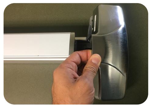
Flip device over & remove (4) screws to remove head assembly. 2.
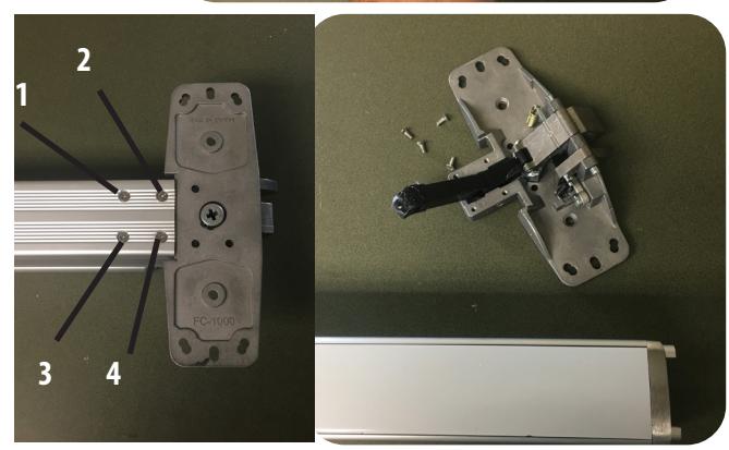
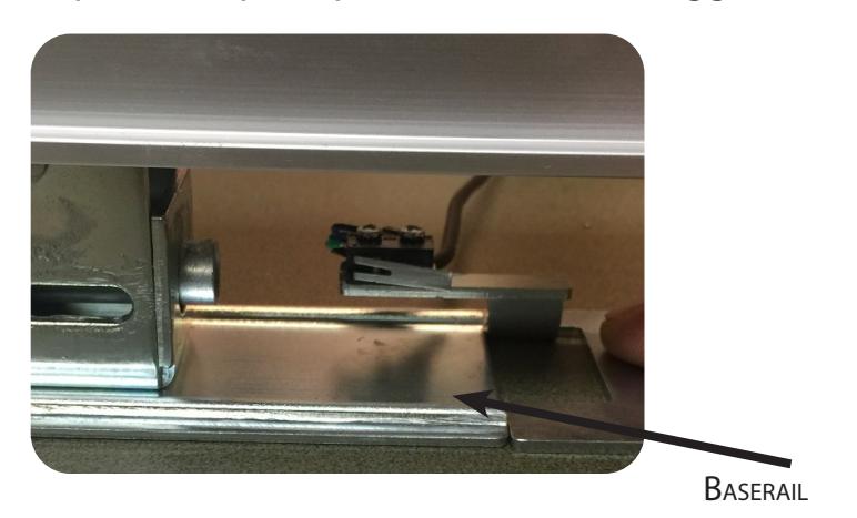
Remove (1) screw from back of baserail then slide push pad off rail housing. 3.
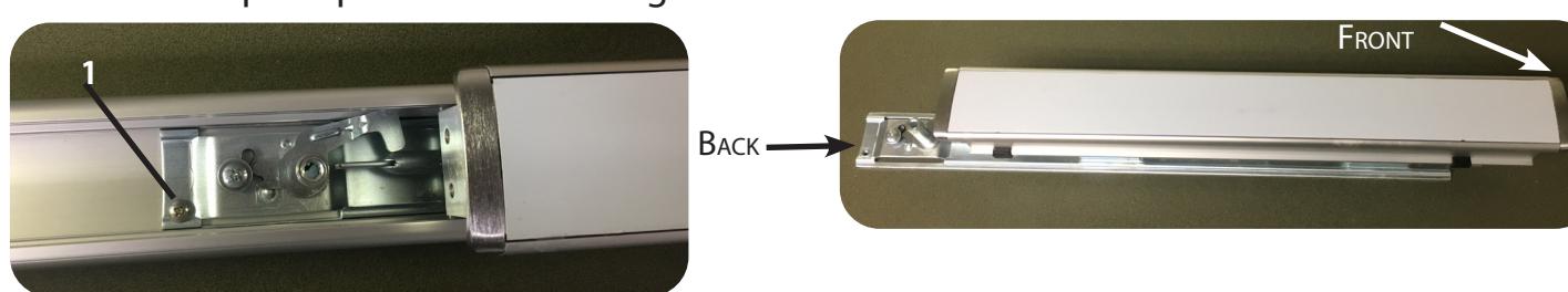
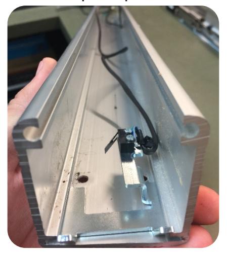
Slide REX Switch on underneath the front of the push pad into the baserail. Depress the push pad to insure REX Triggers. If REX triggers, skip section 2. 5.
2
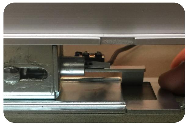
Section 2 - REX Extension
If you're REX is not triggering off the connecting rod you'll need to add the extension arm.
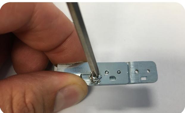
1. Remove REX switch from bracket and add extension arm. Secure with (1) Phillips screw provided.
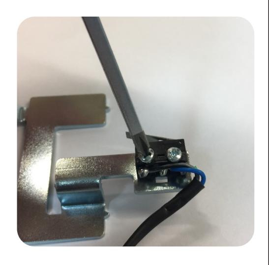
2. Secure with (1) Phillips screw provided.
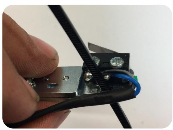
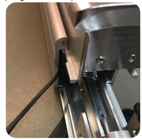
3. Next attach REX switch w/ (2) screws to extension arm mounting location. Add zip tie for a strain relief.
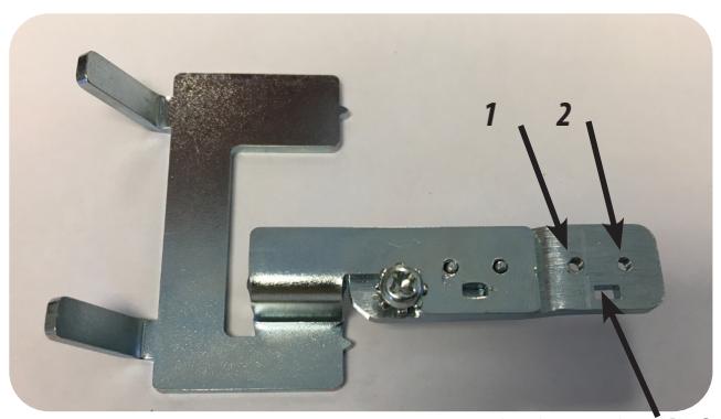
Zip tie/Strain relief
4. Repeat Step 5 from previous section
Section 3 - Reassembly
1. Place REX in the front of the rail housing and chase the wires to the back of the device. Slide the push pad on from the back keeping the wires pulled out of the way on the side.
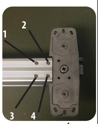
2. Once the pad had been re-installed there should be no gap between the screw holes for the head assembly and the REX.

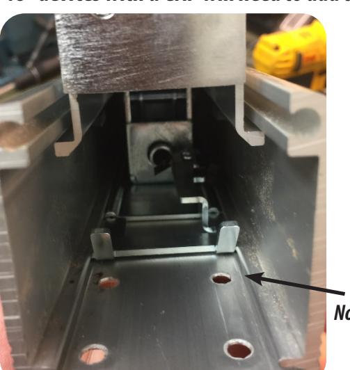

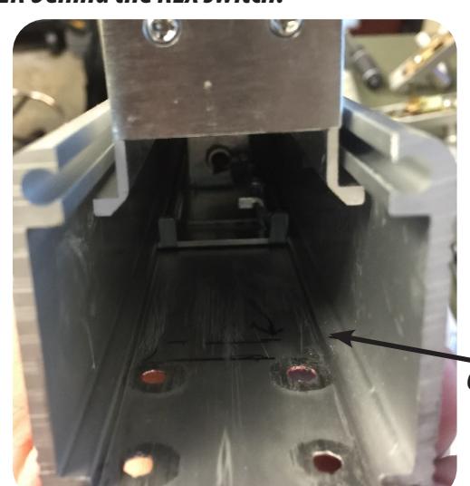
Gap - Add Spacer
3. With switch installed, flip device over & reinstall (4) screw attaching head assembly to rail housing.
4