PD21-M RIM Installation Instruction
Open the original PDF document
View PDF


pd21-m-rim
I N S E R T I n s t r u c t i o n s
The Command Access PD21-M-RIM is our Narrow Stile Grade 1 exit device. It comes with motorized latch retraction utilizing our PTS "Push to Set" technology.
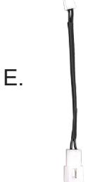
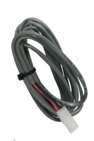
F.
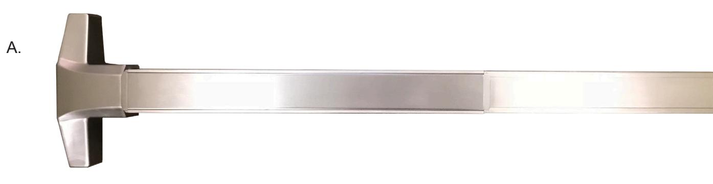
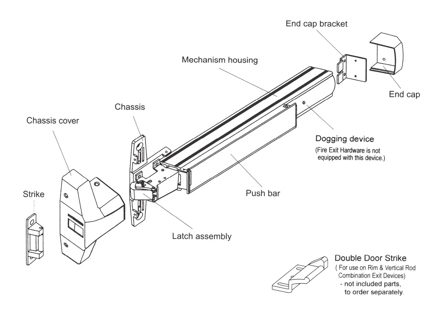
- A. PD21-M RIM Exit device
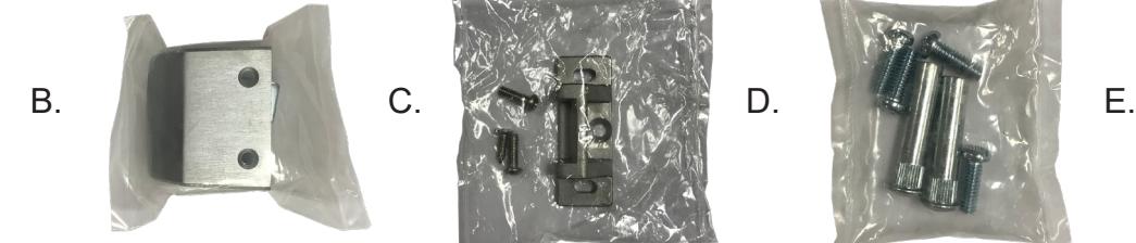
- B. end cap
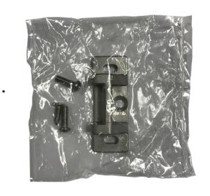
- C. strike pack
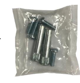
- D. Hardware pack
- E. 50944 mm4s socket lead
- F. 50030 8' power lead
Kit Includes Tools Required
- #2 Phillips head screwdriver
- TAPE MEASURE
- Cordless drill/driver
- ASSORTED DRILL BITS
- 24VDC PORTABLE SOURCE FOR TESTING
- LEVEL
SPECIFICATIONS
- Input Voltage: 24VDC +/- 10% • Wire gauge: Minimum 18 gauge
- Direct wire run no relays or access control units in-between power supply & module
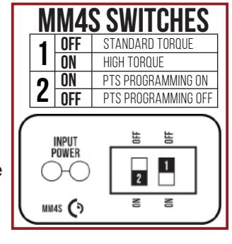
Standard Torque Mode
Average Latch Retraction Current: 900 mA Average Holding Current: 215 mA
High Torque Mode
Average Latch Retraction Current: 2 Amp Average Holding Current: 250 mA
Recommended Power Supplies:
All Command Access exit devices & field installable kits have been thoroughly cycle tested with Command Access power supplies at our factory. If you plan on using a non-Command power supply it must be a filtered & regulated linear power supply.
TECHNICAL INFORMATION

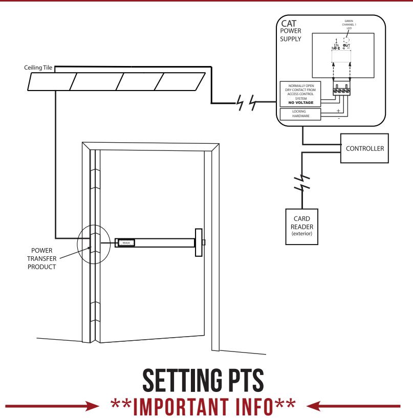

MAKE SURE TO SET PTS BEFORE FINISHING INSTALLATION
- STEP 1 - Select your preferred torque mode (ships in standard torque). Press the device push pad to the desired setting. (We recommend to fully depress and release 5%, giving the device room for changing door conditions.)
- STEP 2 - While depressing the push pad, apply power. (i.e. presenting the credential to the reader).
- STEP 3 Continue to keep the pad depressed, the device will beep 6 times. After the beeps have stopped, release the pad and the adjustment is now complete. If not to your liking repeat the 3 steps.
TROUBLESHOOTING & DIAGNOSTICS
| BEEPS | EXPLANATION | SOLUTION |
|---|---|---|
| 2 Beeps | Over Voltage | > 30V unit will shut down. Check voltage & adjust to 24 V. |
| 3 Beeps | Under Voltage | < 20V unit will shut down. Check voltage & adjust to 24 V. |
| 4 Beeps | Failed Sensor | Verify all 3 sensor wires are installed correctly. Replace sensor if problem persists by contacting office. |
| 5 Beeps | Retraction or dogging failure | After 1st fail: 5 beeps then immediately attempts to retract again. After 2nd fail: 5 beeps with pause in-between for 30 seconds then device attempts to retract again. After 3rd fail: 5 beeps every 7 minutes, device will not attempt to retract. To Reset: Depress bar for 5 seconds at any time. |
| 6 Beeps | PUSH TO SET | Device is recording it's new position and power mode after the 6th beep. |
installation instructions

INSTALLATION INSTRUCTIONS

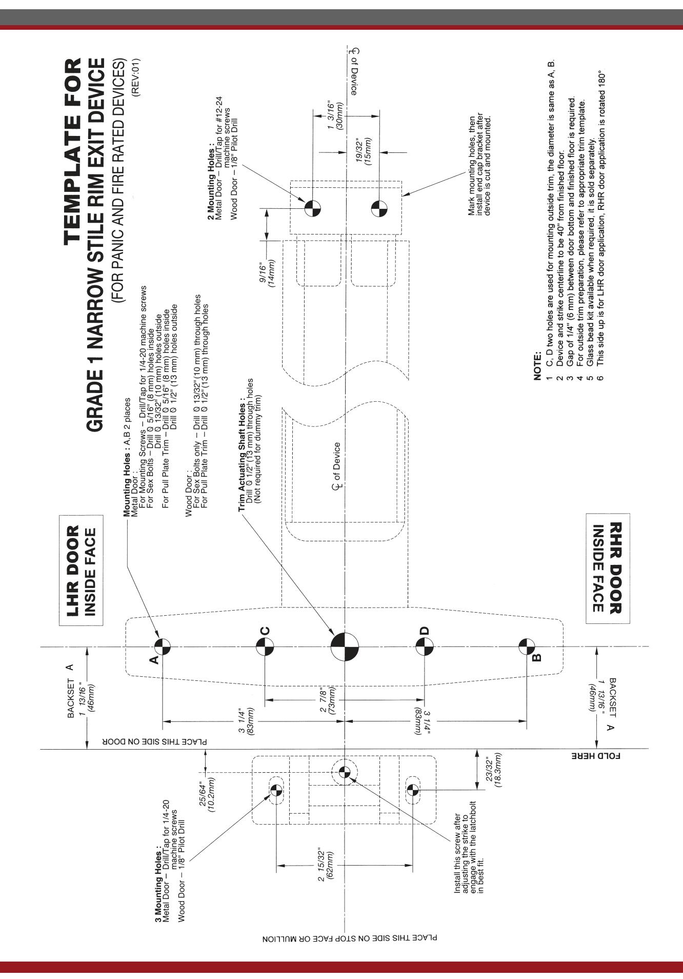
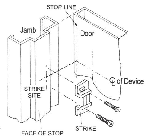
C. INSTALL STRIKE TO FRAME
- 1. Place strike to the drilled position and tighten it to jamb or mullion by supplied screws.
- In case installing with a vertical rod device for a pair of doors, an additional Double Door Strike must be used to replace standard strike provided.
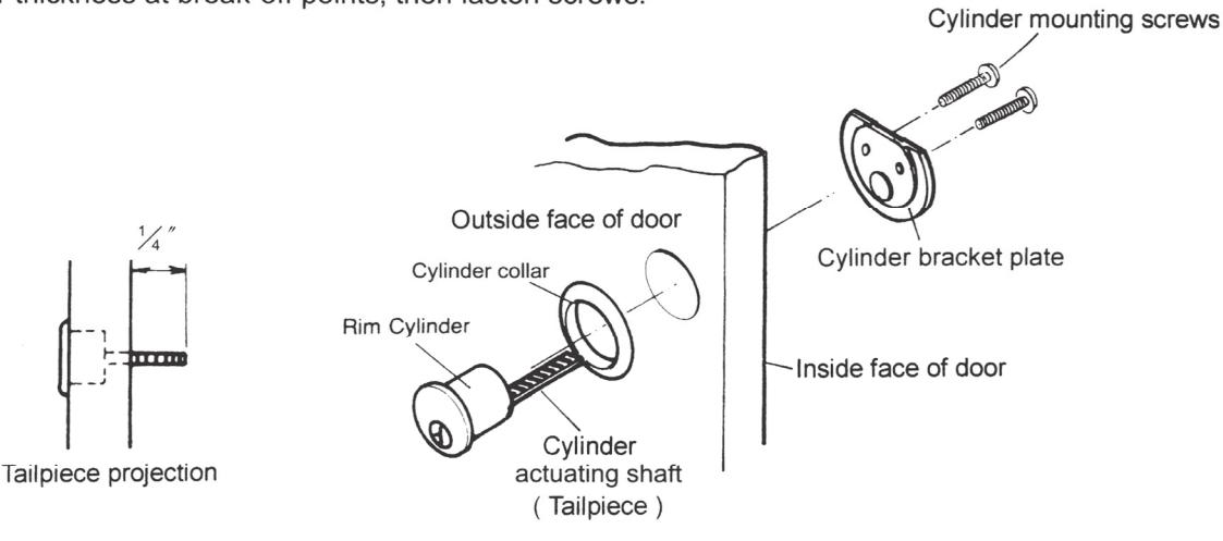
D. IF CYLINDER INCLUDED WITH THE DEVICE
- 1. Drill one 1-3/16" diameter thru hole for the cylinder / bracket plate.
- 2. Insert cylinder and cylinder collar from outside of the door.
- 3. Place bracket plate on inside face of the door.
- 4. Put two cylinder mounting screws thru the bracket plate and into cylinder.
- 5. Cut the cylinder mounting screws and tailpiece to the required door thickness at break-off points, then fasten screws.
E. INSTALL OUTSIDE TRIM
Mark and drill holes for the outside trim. (See Trim Instructions).
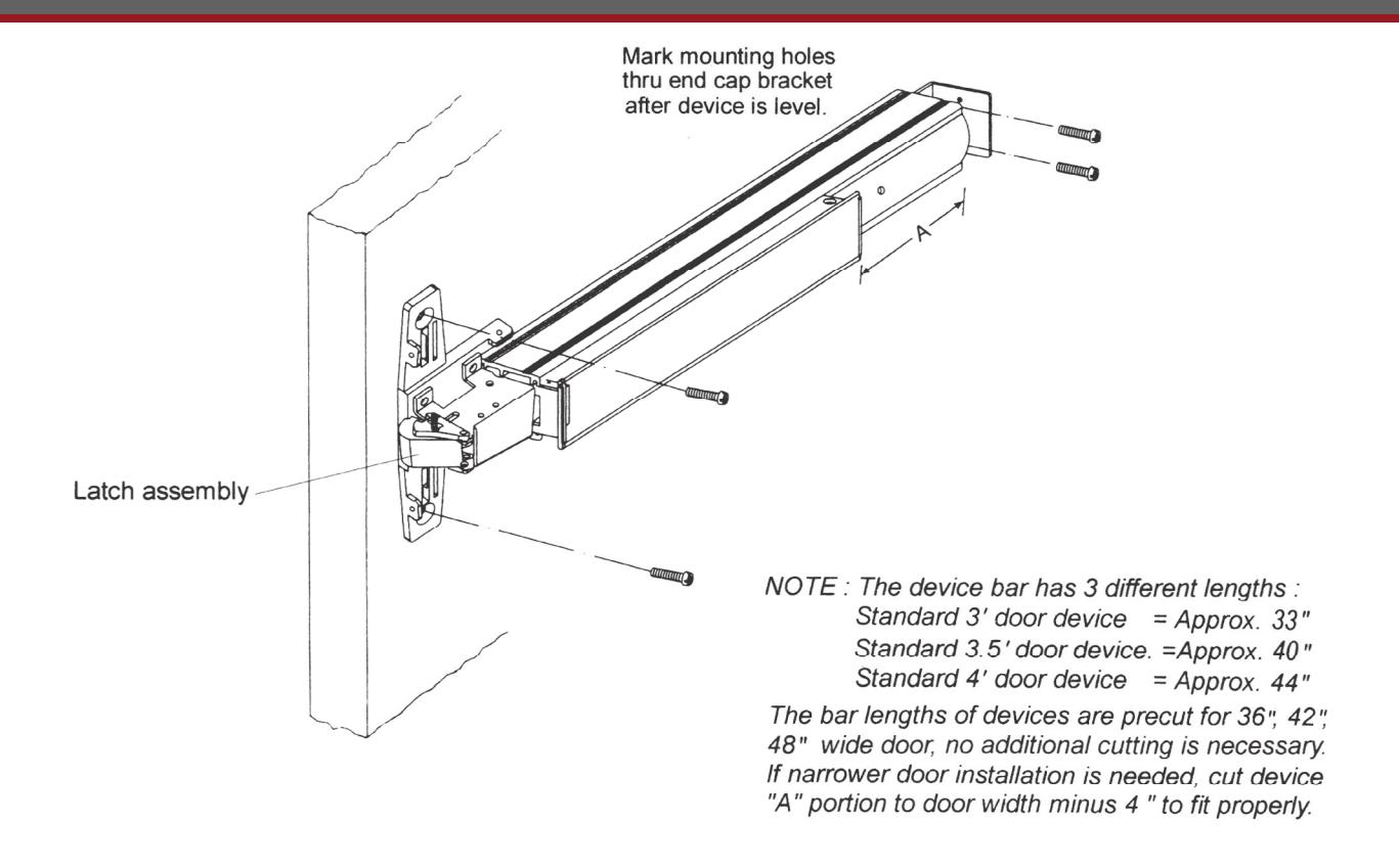
F. INSTALL DEVICE BODY
- Remove chassis cover from latch assembly and end cap from end cap bracket.
- Mount device horizontally to the drilled position by supplied mounted screws, and bolt device chassis to trim or sex bolts (if required).
- 3. Make sure cylinder or trim actuating shaft (tailpiece) can insert into device cam concentrically. (See device cam at right).
- 4. Install end cap bracket on device then screw to door.
- 5. Tighten all screws or bolts.
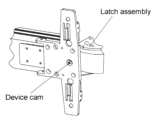
INSERT TRIM ACTUATING SHAFT INTO DEVICE CAM * + ".
INSTALLATION INSTRUCTIONS

G. INSTALL COVERS
-
1. Test push bar operation before installing covers :
- a. No Trim: Latch bolt is retracted by push bar inside.
- b. With Trim: Latch bolt is retracted by push bar inside, key or lever/knob outside.
- Dogging: See dogging description and chart below.
- Make sure and secure latch bolt engagement. Adjust strike if required.
- 3. Install chassis cover on chassis.
- 4. Install end cap.
Note : For increasing the life of this device, dogging device during high traffic period of the day ( Panic device only).
Dogging:
Depress push bar, insert dogging wrench and turn clockwise 35°
|
Depress
push bar |
(a) |
|---|
The push bar will remain pressed and the latch will keep retracted.
Release dogging:
Depress push bar, insert dogging wrench and turn counter-clockwise 35°
|
Depress
push bar |
(6), |
|---|
The push bar will return to up position and the latch will project to lock the door.
Dogging Wrench (Allen Key)
INSTALLATION INSTRUCTIONS