PD15 16 RIM Installation Instruction
Open the original PDF document
View PDF

Installation Instructions PD15-M / PD16 RIM Exit Device
Read all instructions completely before beginning.

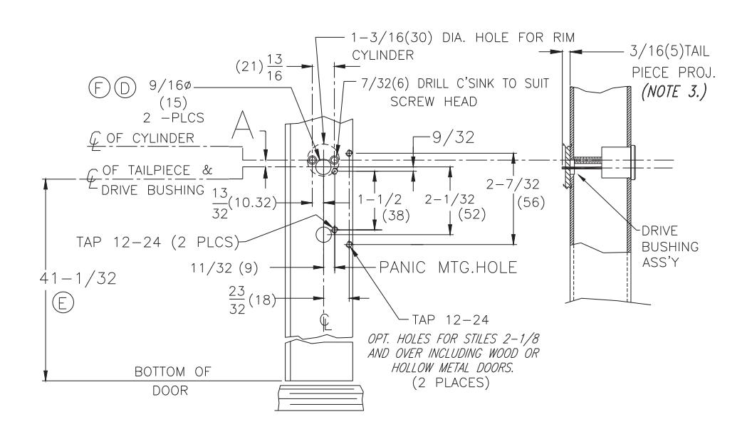
Prepare lock stile.
Drill cylinder mounting holes if required.
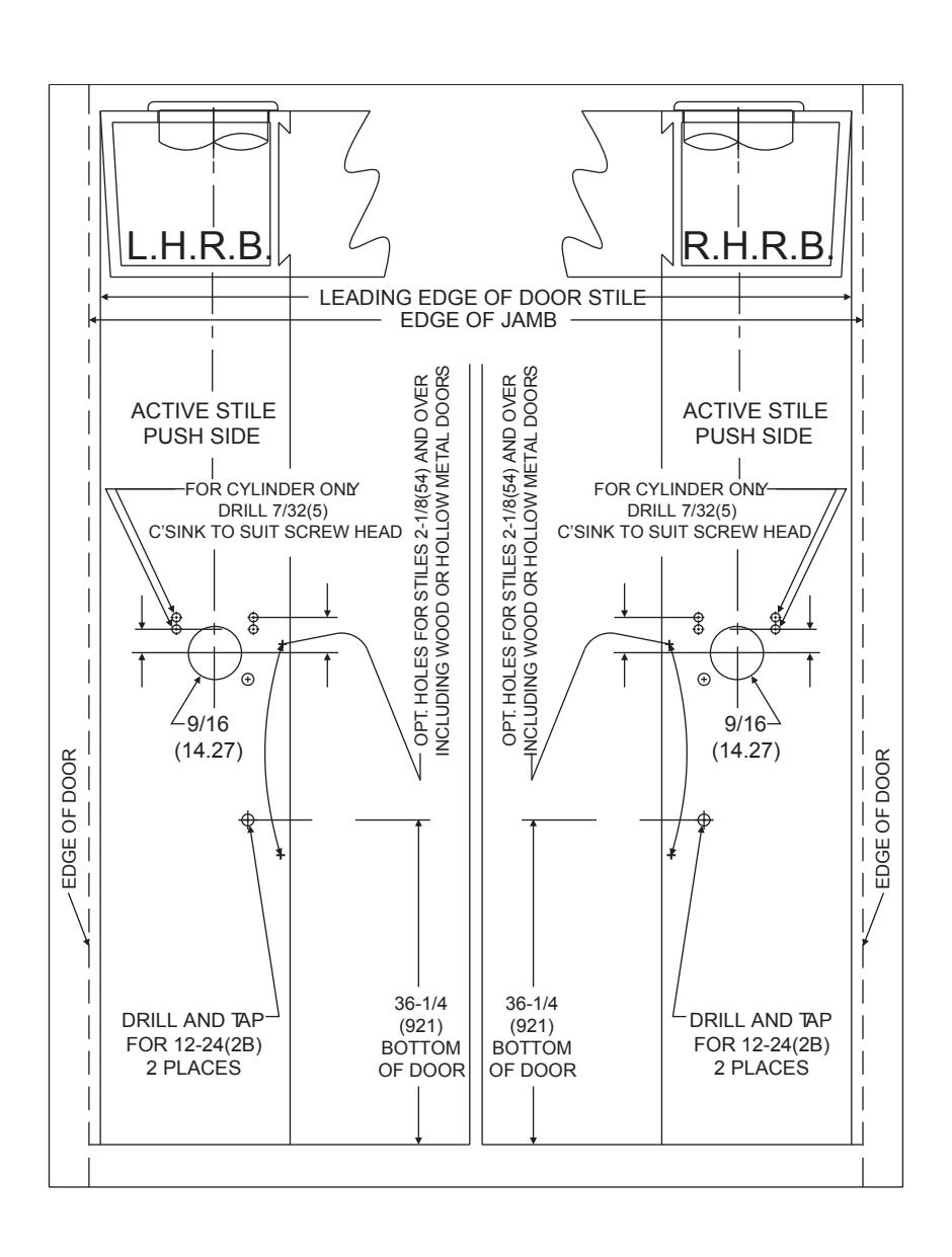
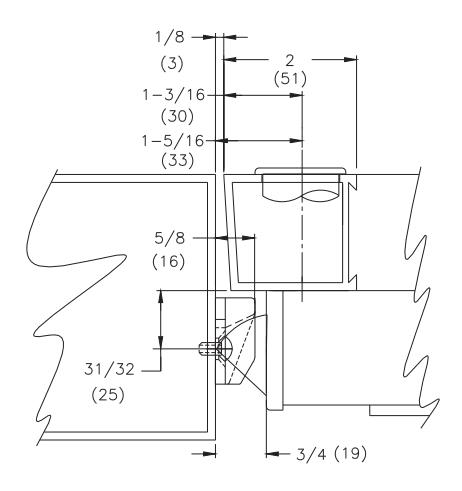
Locate centerline of cylinder on exterior of door and drill if required.
Trim tail piece to fit into panic drive bushing assembly.
Mount cylinder and secure with mounting screws
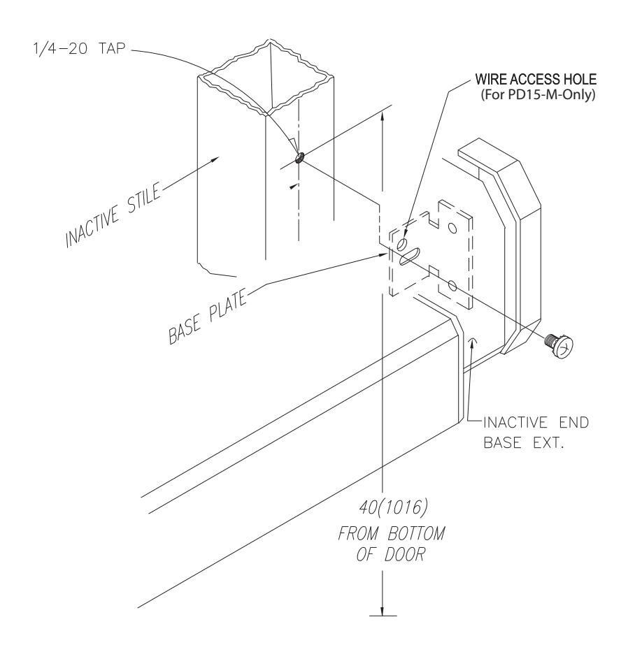
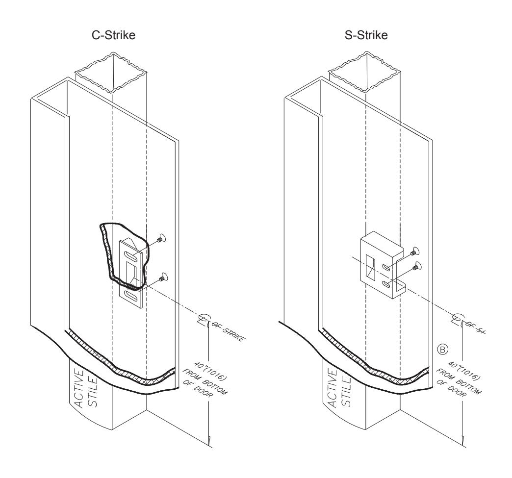
Locate mounting hole on inactive stile. Drill and tap 1/4-/20 thread 40"(1016) from bottom of door.
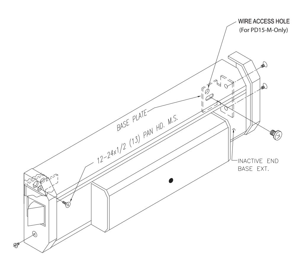
Panic device attachement.
- Remove front and rear end base covers by releasing 6-32 x 3/16(5) flat head screws.
- Secure active end of panic by installing two 12-24x1/2(13) pan head machine screw.
- Secure inactive end with single 1/4-20x1/2(13) round head machine screw (phil.) with attached lock washer through inactive base plate.
- Using the wire access hole as a guide, drill a 3/8" hole into the inactive stile to allow for wire access.
- Proceed by re-installing filler plates and base covers on each end of panic base.
Install strike.
To install strike, locate 10-24x5/8(16) taps on active stile (2 places) Mount and secure strike.

MM4
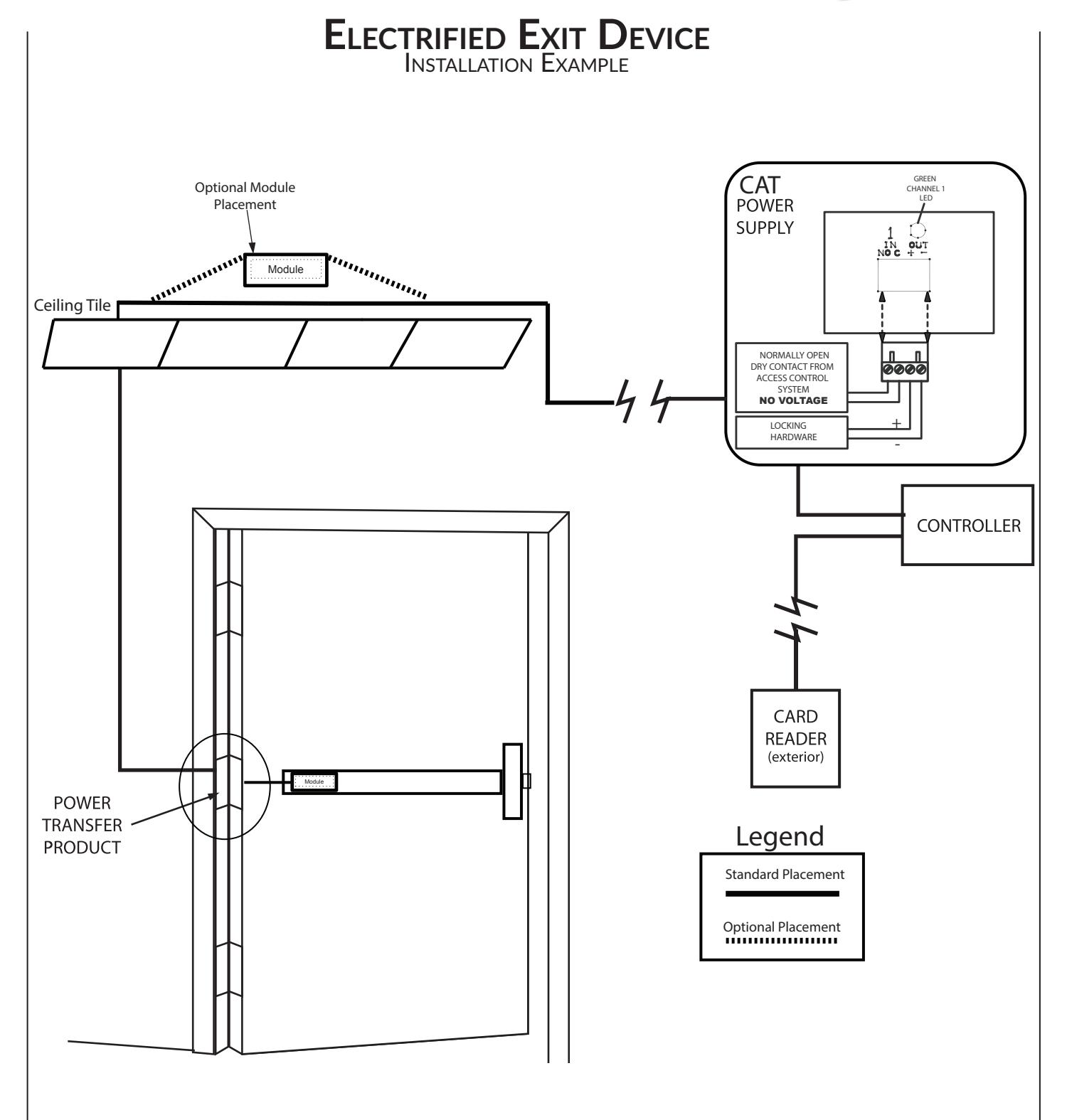
TECHNICAL INFORMATION

SpecificationS
• Input Voltage: 24VDC +/- 10%
• Average Latch Retracton Current: 1.3 Amp
• Average Holding Current: 170 mA
• Wire gauge: Minimum 20 gauge

Setting PtS
**Important Info**
Make sure to set PTS before fnishing installaton!
- Step 1- Press the device push pad to the desired setng. (this can be fully depressed or less than fully depressed).
- Step 2- While depressing the push pad, apply power. (i.e. presentng the credental to the reader).
- Step 3- Contnue to keep pad depressed, the device will beep 6 tmes. Afer the beeps have stopped, release the pad and now the adjustment is complete. If not to your liking repeat the three steps. That's all there is to it.
trouBleShooting & DiagnoSticS
| BeePS | exPlanation | Solution |
|---|---|---|
| 2 Beeps | Over Voltage | > 28V unit will shut down. Check voltage & adjust to 24 V. |
| 3 Beeps | Under Voltage | < 22V unit will shut down. Check voltage & adjust to 24 V. |
| 4 Beeps | Failed Sensor |
Verify all 3 sensor wires are installed correctly. Replace sensor if
problem persists by contactng ofce. |
| 5 Beeps | Forced Release | Device will automatcally re-engage within 5 seconds. |
| 6 Beeps |
Push pad is depressed. Device is
re-adjustng |
Check to make sure the push pad is not stuck or catching on
anything. |
| 7 Beeps |
Over-travel or mechanical
obstructon |
If mechanical obstructon, remove & push pad down untl
beeping stops to reset. If no obstructon, the pad may have been pushed in too far during PTS calibraton. Recalibrate with the pad slightly out. If problem persists, verify the magnet is within 1/4" of the sensor at the end of travel. 1 |

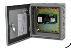
recommenDeD Power SuPPlieS:
All Command Access exit devices & field installable kits have been thoroughly cycle tested with Command Access power supplies at our factory.
For more informaton click here or go to our website