PD15 16 CVR Installation Instruction
Open the original PDF document
View PDF

Installation Instructions PD15-M / PD16 CVR Exit Device
Read all instructions completely before beginning.
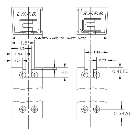
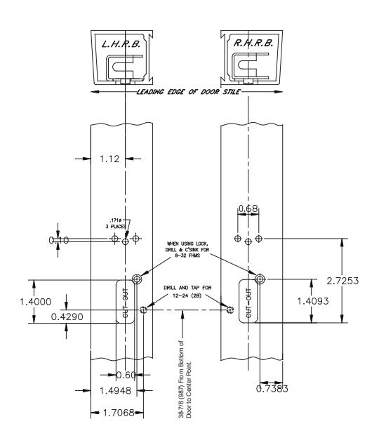
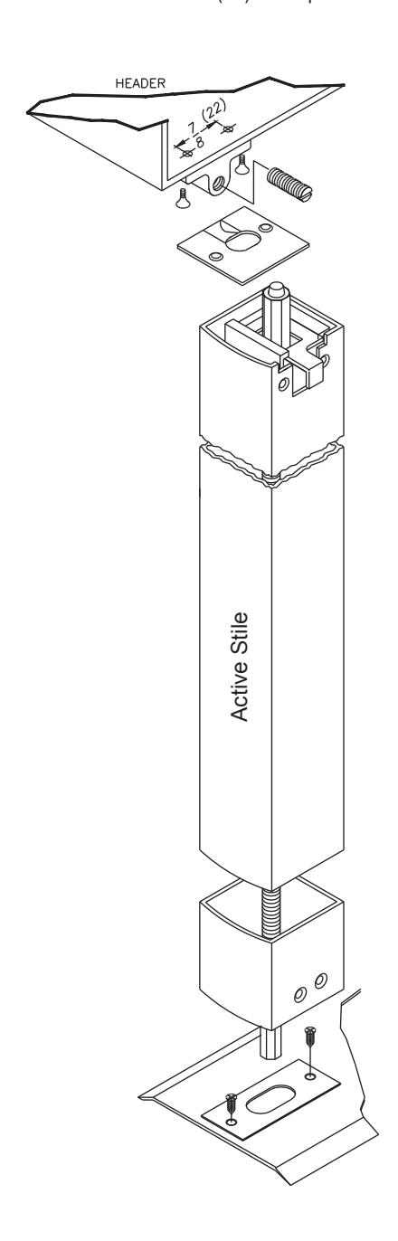
Prepare lock stile.
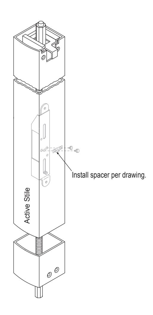
Install Rod & Case assembly into active stile.
Secure with 2 ea. 8-32 x 1/4 cap screws.
Install Top & Bottom Strikes.
Secure with 2 ea. 8-3/4(19) self tap screws.
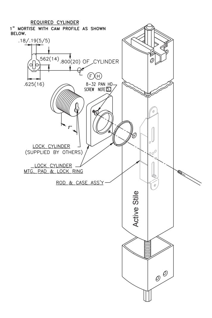
Install Trim and Cylinder.
Install one 8-32 pan head screw partially to suit nominal wall thickness of 1/8" or 3/16" Install pad assembly and rotate clockwise until it locks into position. Install single 8-32 x 1-15/16" screw and tighten.
NOTE:
Use 8-32x5/16 pan head on 1/8" wall thickness Use 8-32x5/3/8 pan head on 3/16" wall thickness
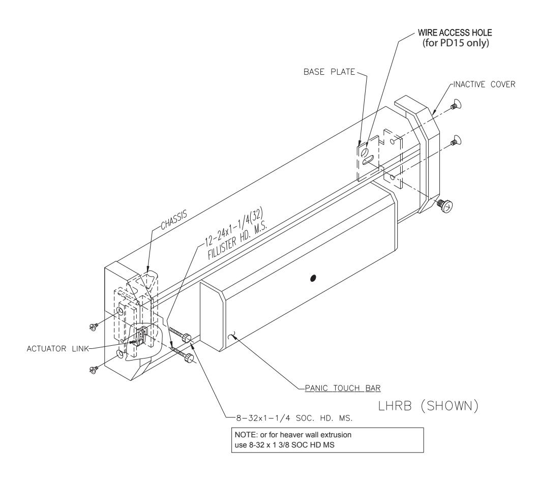
Panic Attachment.
- Remove front and rear end base covers by releasing 6-32x3/16(5) & 12-24x1-1/4(32) fillister head screw through chassis and one 8-32x1-1/4 head machine screw, secure inactive end with single 1/4-20x1/2(13) round head machine screw (phil.) with semsthrough inactive base plate.
- Using the wire access hole as a guide, drill a 3/8" hole into the inactive stile to allow for wire access.
- Proceed by re-installing base cover on each end of panic base.
Adjust Top & Bottom Bolts.
Adjust Top & Bottom Bolts allowing for 1/2"(13) of bolt to extend from vertical stile. Install bolt guides top & bottom with (2) each #10x1/2(13) flat head self-tapping screws. Depress push bar, top bolt should lock in the retracted (unlocked) position. If locking does not occur readjust bolts in half turn increments until locking occurs. Verify operation by fully depressing touch bar to achieve dogging or full retraction of bolts.
Top Bolt Adjustment:
Release top and bottom bolts by depressing trigger on top bolt guide assembly. Position top bolt 1/2"(13) from top edge of active stile.
Bottom Bolt Adjustment:
Fully depress push bar, retracting top and bottom rods. Adjust bottom bolt per detail "B" Manual Check:
With top and bottom bolts fully retracted, depress trigger release, rods will then extend to the locked position. Install trip bracket and adjust set screw so that when door closes, top bolt guide trigger contacts set screw and allows bolts to extend.

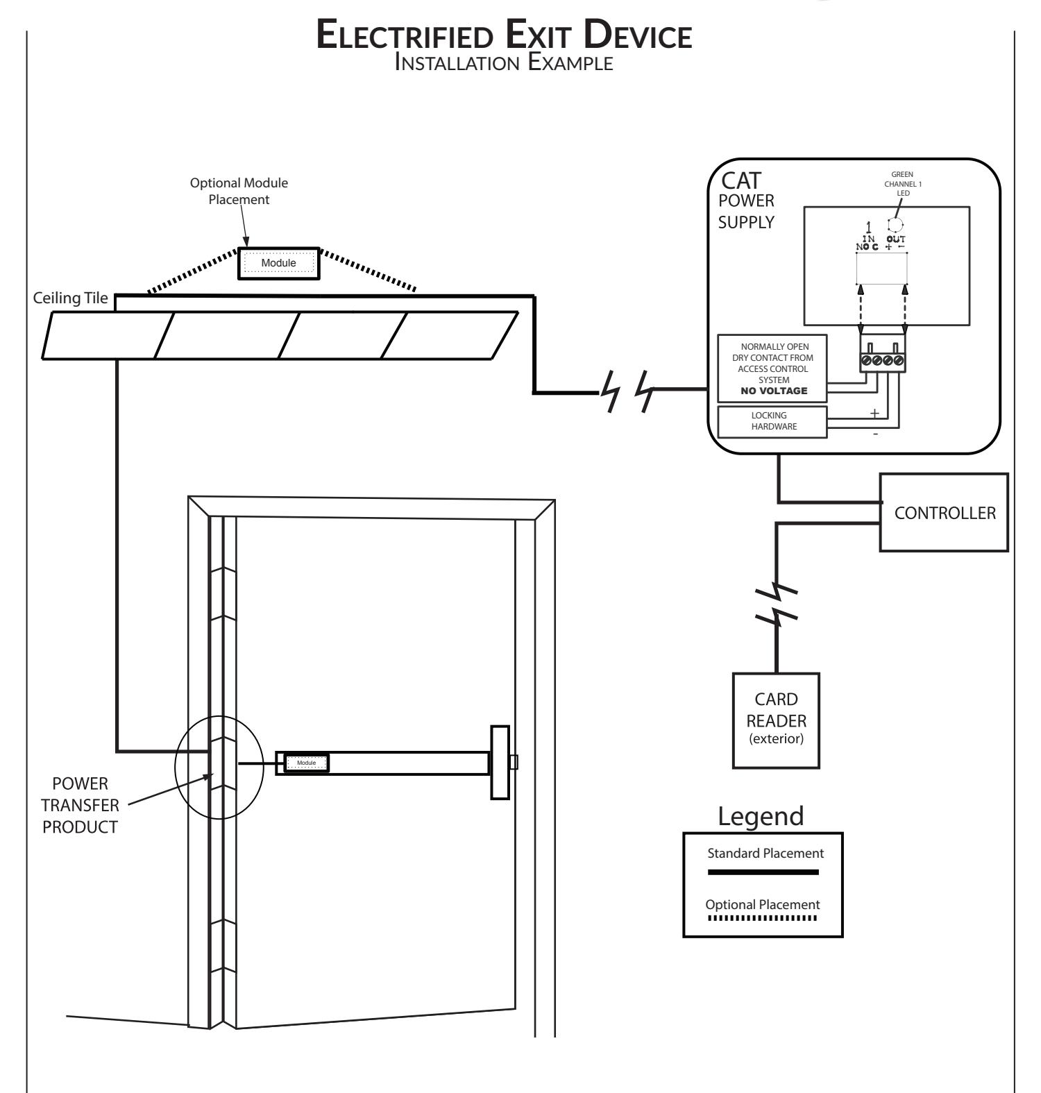
recommenDeD Power SuPPlieS:
All Command Access exit devices & field installable kits have been thoroughly cycle tested with Command Access power supplies at our factory.
For more informaton click here or go to our website

MM4
TECHNICAL INFORMATION

SpecificationS
• Input Voltage: 24VDC +/- 10%
• Average Latch Retracton Current: 1.3 Amp
• Average Holding Current: 170 mA
• Wire gauge: Minimum 20 gauge
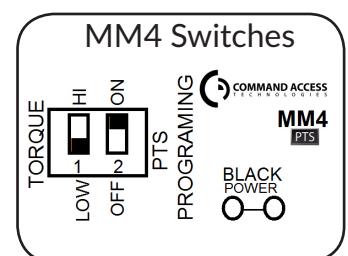
Setting PtS
**Important Info**
Make sure to set PTS before fnishing installaton!
- Step 1- Press the device push pad to the desired setng. (this can be fully depressed or less than fully depressed).
- Step 2- While depressing the push pad, apply power. (i.e. presentng the credental to the reader).
- Step 3- Contnue to keep pad depressed, the device will beep 6 tmes. Afer the beeps have stopped, release the pad and now the adjustment is complete. If not to your liking repeat the three steps. That's all there is to it.
trouBleShooting & DiagnoSticS
| BeePS | exPlanation | Solution |
|---|---|---|
| 2 Beeps | Over Voltage | > 28V unit will shut down. Check voltage & adjust to 24 V. |
| 3 Beeps | Under Voltage | < 22V unit will shut down. Check voltage & adjust to 24 V. |
| 4 Beeps | Failed Sensor |
Verify all 3 sensor wires are installed correctly. Replace sensor if
problem persists by contactng ofce. |
| 5 Beeps | Forced Release | Device will automatcally re-engage within 5 seconds. |
| 6 Beeps |
Push pad is depressed. Device is
re-adjustng |
Check to make sure the push pad is not stuck or catching on
anything. |
| 7 Beeps |
Over-travel or mechanical
obstructon |
If mechanical obstructon, remove & push pad down untl
beeping stops to reset. If no obstructon, the pad may have been pushed in too far during PTS calibraton. Recalibrate with the pad slightly out. If problem persists, verify the magnet is within 1/4" of the sensor at the end of travel. 1 |