PD 18-M RIM Installation Instruction
Open the original PDF document
View PDF

PD18-M-RIM
Installation Instructions
The PD18-M-RIM is a storefront grade 1 exit device equipped with motor-driven latch retraction. Retrofits Adams Rite 8800 series.
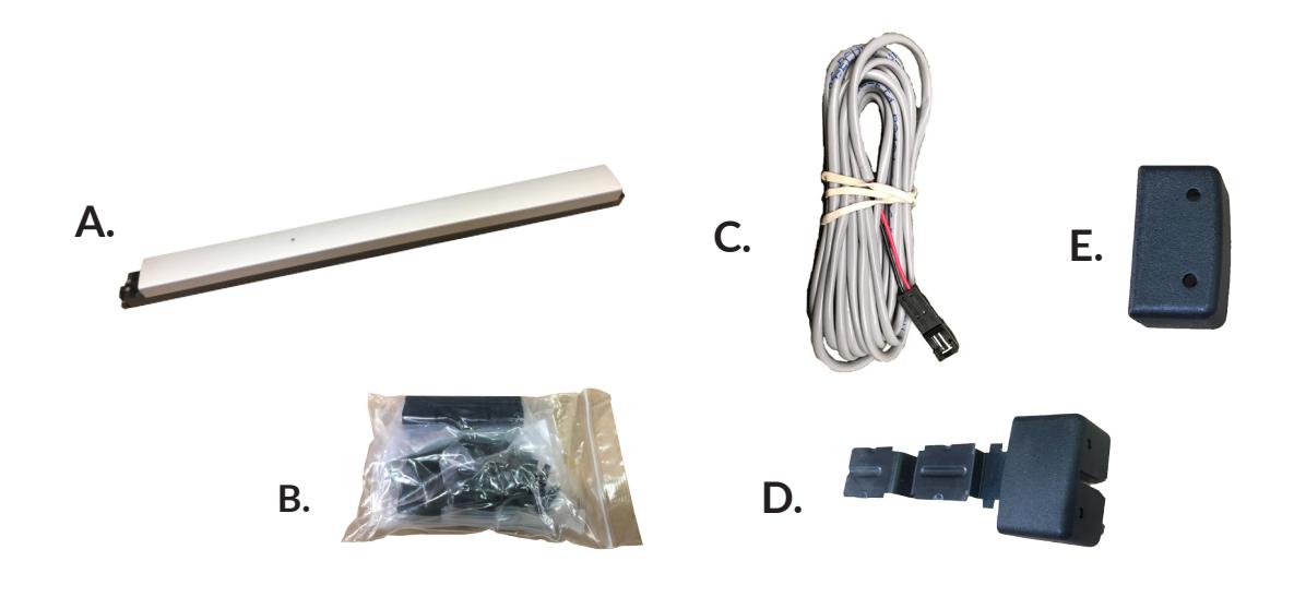
PD18-M-RIM Includes
- A. RIM Exit Device
- B. Hardware pack
- C. 8' Power Lead
- D. Lock Stile End Cap pack
- E. Hinge Stile End Cap pack
Tools Required
- Cordless Drill
- Needle Nose Pliers
- Measuring Tape
- 1/8 Drill Bit
- 1/4 Drill Bit
- #25 Drill Bit
TECHNICAL INFORMATION

Specifications
- Input Voltage: 24VDC +/- 10% • Wire gauge: Minimum 18 gauge
- Direct wire run no relays or access control units in-between power supply & module
Standard Torque Mode- Ships Standard
- Average Latch Retraction Current: 1 A
- Average Holding Current: 180 mA
High Torque Mode
- Average Latch Retraction Current: 2 Amp
- Average Holding Current: 250 mA
MM4 Switches ON OFF - OFF - - Standard Torque PTS programming locked - ON High Torque 1 Switch Program PTS programming ON

** Important Info **
Make sure to set PTS before finishing installation!

- Step 1 Select your preferred torque mode (ships in standard torque) Press the device push pad to the desired setting. (Recommend to fully depress and release 5%, giving the device a little room for changing door conditions.)
- Step 2 While depressing the push pad, apply power. (i.e. presenting the credential to the reader).
- Step 3 Continue to keep pad depressed, the device will beep 6 times. After the beeps have stopped, release the pad and now the adjustment is complete. If not to your liking repeat the three steps. That's all there is to it.
- Step 4 Once you found the correct location switch the dip switch to lock PTS & Torque programming.
Troubleshooting & Diagnostics
| Beeps | Explanation | Solution |
|---|---|---|
| 2 Beeps | Over Voltage | > 28.0V unit will shut down. Check voltage & adjust to 24 V. |
| 3 Beeps | Under Voltage | < 22V unit will shut down. Check voltage & adjust to 24 V. |
| 4 Beeps | Failed Sensor |
Verify all 3 sensor wires are soldered on circuit board and plug into MM4 module.
If loose wire is found, please contact our office. |
| 5 Beeps |
Retraction or Dogging
failure |
Device physically binding during retraction or pulled from the dogged position.
After 1st fail: 5 beeps then immediately attempts to retract again. After 2nd fail: 5 beeps with pause in-between for 30 seconds then device attempts to retract again. After 3rd fail: 5 beeps every 7 minutes, device will not attempt to retract. To Reset: Depress bar for 5 seconds at any time. |
| 6 Beeps | Push to Set | Device is recording it's new position and power mode after the 6th beep. |
2

ELECTRIFIED EXIT DEVICE
Installation Example
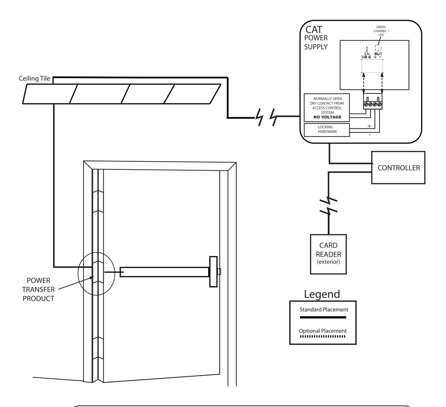
RECOMMENDED POWER SUPPLIES:
All Command Access exit devices & field installable kits have been thoroughly cycle tested with Command Access power supplies at our factory.
- PS210
- PS220/220B
- PS440B
- PS480B
- PS1
- PS2/2B
- For more information click here or go to our website
• PS5-4
| DIA |
DO
SIZ OR E |
|||
|---|---|---|---|---|
| 26 | 30 | |||
| .88 | " | |||
| 32 | 36 | |||
| .88 | " | |||
| 38 | 42 | |||
| .88 | " | |||
| 44 | 48 | |||
| .88 | " | |||
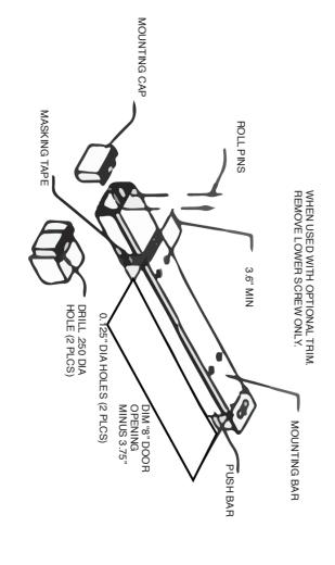
CUT-OFF INSTRUCTIONS FOR NON STANDARD DOORS
DRIVE OUT TWO ROLL PINS
1.
2.
3.
4.
- REMOVE MOUNTING CAP
- COLLAPSE BAR AND TAPE DOWN IN THE AREA OF CUT-OFF RIVET DETERMINE EXTRUSION LENGTH (8" DIM) DIMENSIONS FROM
- CENTERLINE TO NEW CUT-OFF LENGTH
- EXTRUSION LENGTH ON TAPE MEASURE MOUNTING BAR (NOT PUSH BAR) AND MARK
5.
- 6. SAW OFF EXCESS LENGTH, REMOVE TAPE AND DE-BURR 7. LAY MOUNTING CAP OVER MOUNTING BAR AND USE AS GUIDE
- TWO ROLL PINS INTO HOLES. REINSTALL MOUNTING CAP INTO MOUNTING BAR AND DRIVE
TO DRILL TWO 1/8" DIAMETER HOLES.
8.
SEPARATING PUSH BAR AND MOUNTING BAR PROCEDURE
DRILL .250 DIA
REMOVE BOTH END CAPS. THE RETAINER IS ATTACHED TO THE
1.
NOSE CAP.
2.
3.
- SLIDE PUSH BAR TOWARD HINGE SIDE OF DOOR
- CONTINUE TO SLIDE THE PUSH BAR PAST THE PIVOT PLATE HAT RIDES IN PUSH BAR TRACK.
- 4. PLATE. PLATE OUT OF TRACK UNTIL PUSH BAR IS FREE OF MOUNTING SLIDE PUSH BAR IN OPPOSITE DIRECTION KEEPING PIVOT
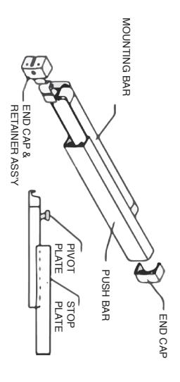
INSTALLING PUSH BAR TO MOUNTING BAR
1.
PUSH BAR AND MOUNTING BAR ALIGN. TRACK ON PUSH BAR AND SLIDE IN OPPOSITE DIRECTION UNTIL SECOND PIVOT PLATE IS EXPOSED. INSERT PIVOT PLATE INTO PLATE NEAREST HINGE INTO TRACK OF PUSH BAR UNTIL IS ON THE LATCH END OF ASSEMBLED UNIT) SLIDE THE PIVOT DOOR, FIND STOP PLATE STAKED INTO PUSH BAR.( THIS PLATE WITH PUSH BAR IN HAND AND MOUNTING BAR ATTACHED TO
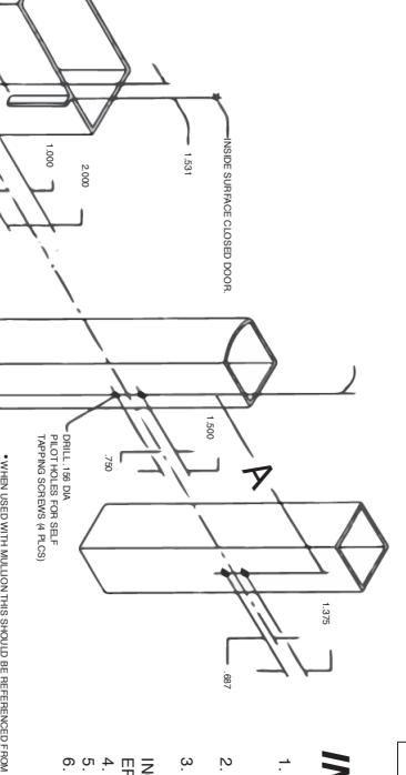
RIM PREPARATION
Installation Template
All prep is shown on interior side of the door, except where noted. Right hand door shown. (LHR)
NOTE - These dimensions and templates assume a door of 1 3/4". For doors of other thickness, please consult factory.
METRIC EQUIVALENTS
| 1.156 | 1.000 | .813 | .750 | .687 | .406 | .375 | .250 | .219 | .125 |
INCH
ES |
| 29.36 | 25.40 | 20.65 | 19.05 | 17.45 | 10.31 | 9.53 | 6.35 | 5.56 | 3.17 | MM |
| 32.88 | 30 | 26.88 | 4.125 | 3.6 | 3.00 | 2.000 | 1.531 | 1.500 | 1.375 |
INCH
ES |
|
835.1
5 |
762.0
0 |
682.7
5 |
104.7
8 |
91.44 | 76.20 | 50.80 | 38.89 | 38.10 | 34.93 | MM |
| 1 1/8 | 5/8 | 3/16 | 1/16 | 48 | 44.88 | 42 | 38.88 | 36 |
INCH
ES |
|
| 28.58 | 15.88 | 4.75 | 1.59 |
1219.
20 |
1139.
95 |
1066.
80 |
987.5
5 |
914.4
0 |
MM |
INSTALL INSTRUCTIONS
- ACCORDING TO INSTRUCTIONS WITH RIVNUT TOOL. 1. CRIMP ALL RIVNUTS IN STILE AND JAMB SKIP STEPS 2 AND 3 IF CYLINDER IS NOT USED.
- 2. INSTALL CYLINDER, USING SCREWS SUPPLIED WITH CYLINDER.
- 3. INSTALL MOUNTING BAR ( IF CYLINDER IS USED. BE SURE THAT TAILPIECE PROTRUDES 3/16 INCH TO ENGAGE CYLINDER PROPERLY.)
- 5. INSTALL END CAPS 4. INSTALL PUSH BAR TO MOUNTING BAR.
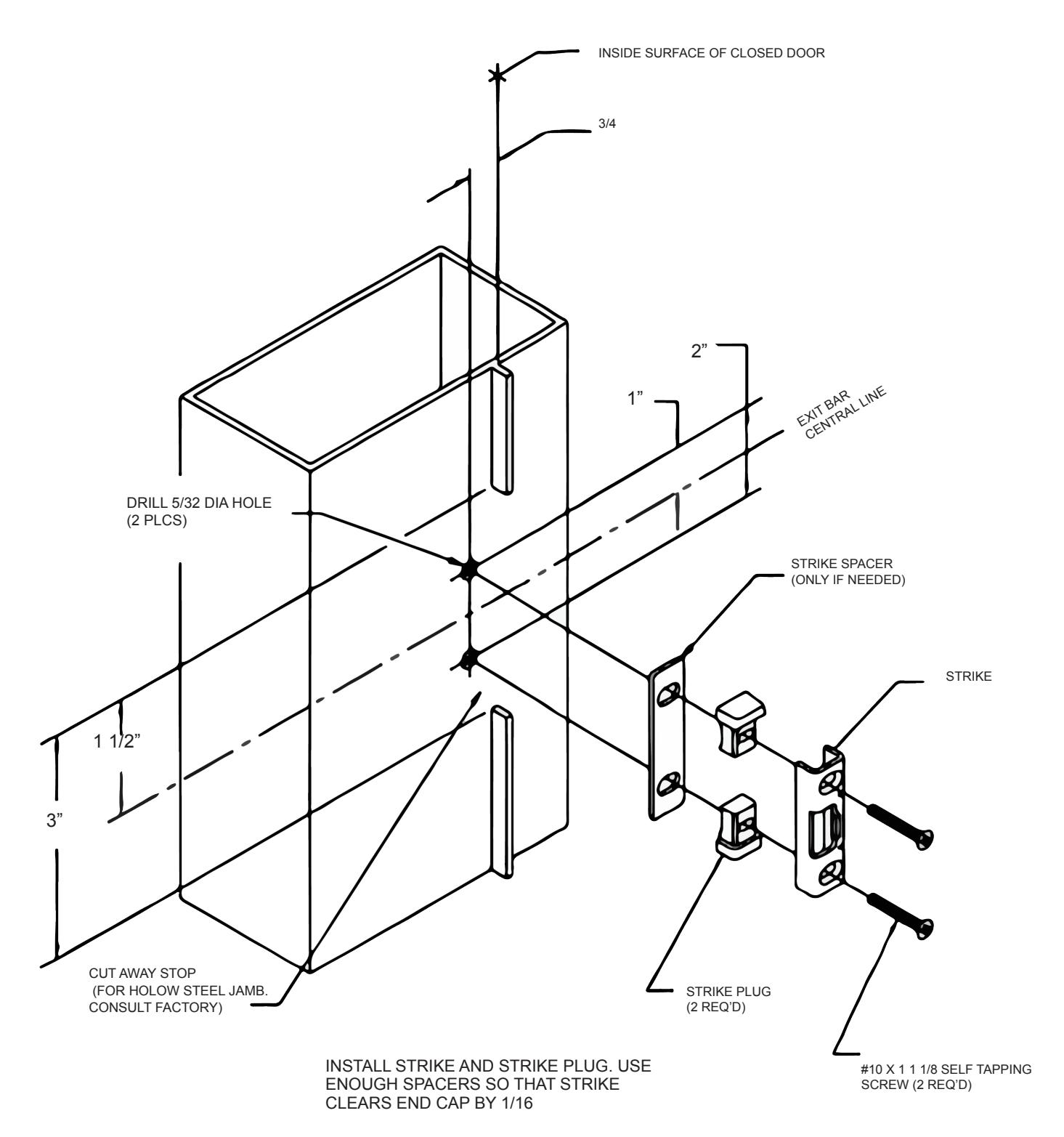
- SPACERS SO THAT STRIKE CLEARS CAP BY 6. INSTALL STRIKE AND STRIKE PLUG. USE ENOUGH 1/16"
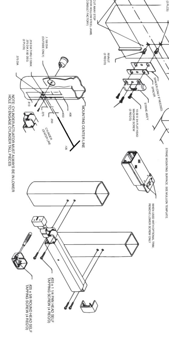
CUT AWAY STOP
STRIKE PREPARATION AND INSTALLATION

Instructions