PD 18-M CVR Installation Instruction
Open the original PDF document
View PDF

PD18-M-CVR
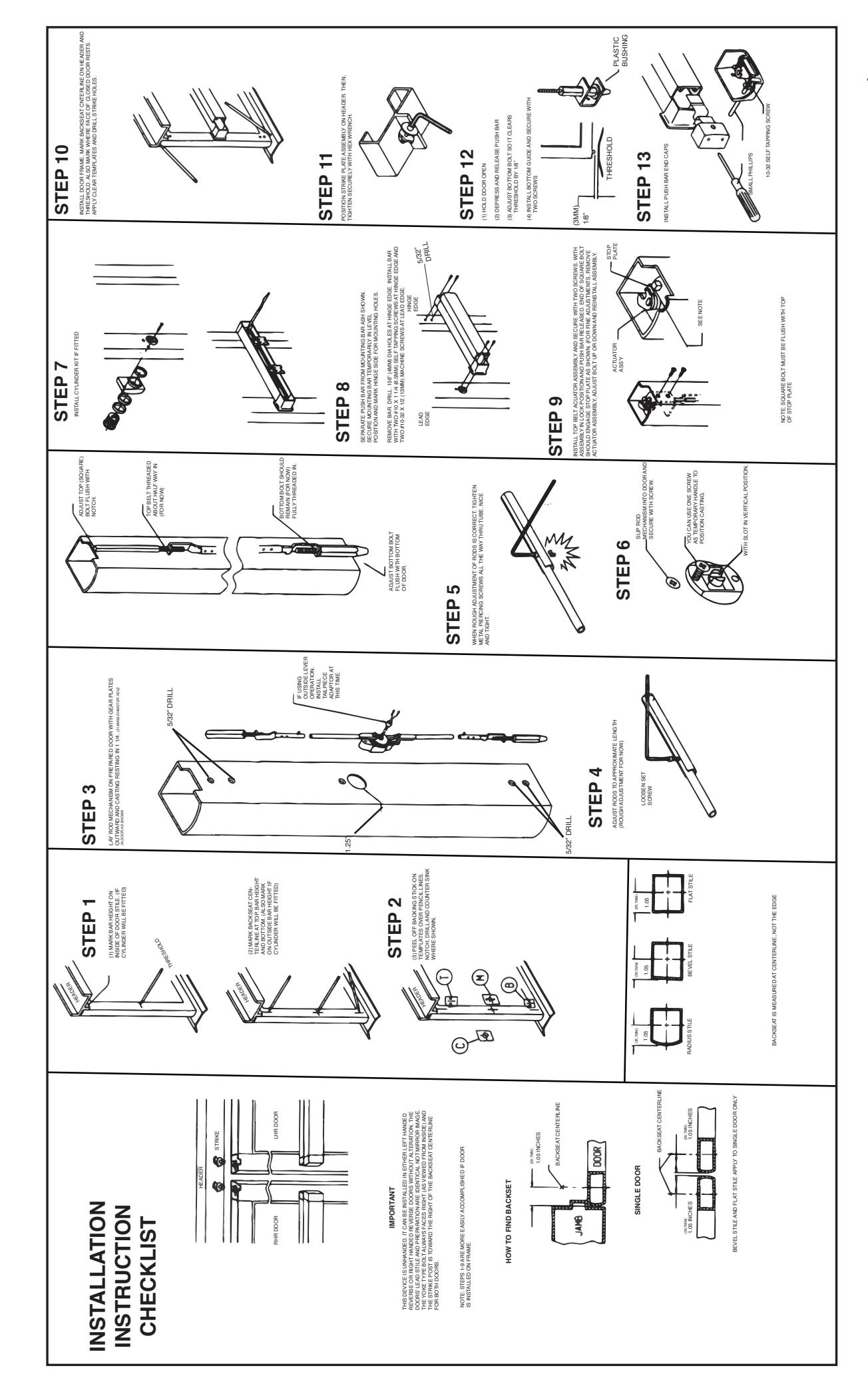
INSTALLATION INSTRUCTIONS
The PD18-M-CVR is a storefront grade 1 exit device equipped with motor driven latch retraction.
Retrofits Adams Rite 8600 series.


PD18-M-CVR Includes
- A. CVR Device
- B. CVR Rods
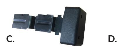
- C. Head Cover End Cap
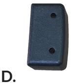
- D. Hinge Stile End Cap
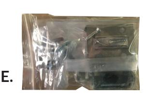
- E. CVR Strike Pack
- F. 8' Power Lead
Tools Required
- Cordless Drill
- Needle nose Pliers
- Measuring Tape
- 3/4" Drill Bit
- 5/32 Drill Bit
- Counter Sink Bit
- 1 1/4" Hole Saw
TECHNICAL INFORMATION

Specifications
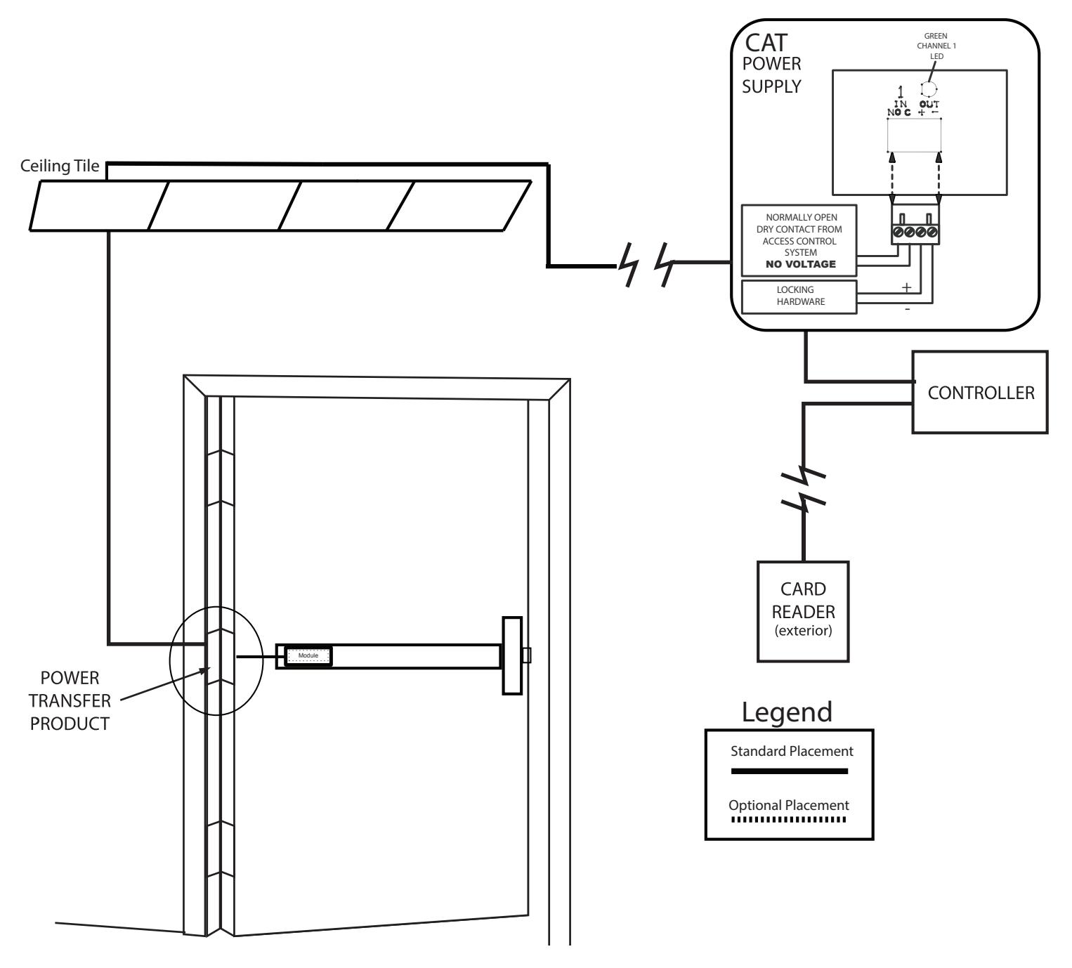
- Input Voltage: 24VDC +/- 10% • Wire gauge: Minimum 18 gauge
- Direct wire run no relays or access control units in-between power supply & module
Standard Torque Mode- Ships Standard
- Average Latch Retraction Current: 1 A
- Average Holding Current: 180 mA
High Torque Mode
- Average Latch Retraction Current: 2 Amp
- Average Holding Current: 250 mA
MM4 Switches ON OFF - OFF - - Standard Torque PTS programming locked - ON High Torque 1 Switch Program PTS programming ON

Make sure to set PTS before finishing installation!

- Step 1 Select your preferred torque mode (ships in standard torque) Press the device push pad to the desired setting. (Recommend to fully depress and release 5%, giving the device a little room for changing door conditions.)
- Step 2 While depressing the push pad, apply power. (i.e. presenting the credential to the reader).
- Step 3 Continue to keep pad depressed, the device will beep 6 times. After the beeps have stopped, release the pad and now the adjustment is complete. If not to your liking repeat the three steps. That's all there is to it.
- Step 4 Once you found the correct location switch the dip switch to lock PTS & Torque programming.
Troubleshooting & Diagnostics
| Beeps | Explanation | Solution |
|---|---|---|
| 2 Beeps | Over Voltage | > 28.0V unit will shut down. Check voltage & adjust to 24 V. |
| 3 Beeps | Under Voltage | < 22V unit will shut down. Check voltage & adjust to 24 V. |
| 4 Beeps | Failed Sensor |
Verify all 3 sensor wires are soldered on circuit board and plug into MM4 module.
If loose wire is found, please contact our office. |
| 5 Beeps |
Retraction or Dogging
failure |
Device physically binding during retraction or pulled from the dogged position.
After 1st fail: 5 beeps then immediately attempts to retract again. After 2nd fail: 5 beeps with pause in-between for 30 seconds then device attempts to retract again. After 3rd fail: 5 beeps every 7 minutes, device will not attempt to retract. To Reset: Depress bar for 5 seconds at any time. |
| 6 Beeps | Push to Set | Device is recording it's new position and power mode after the 6th beep. |
2
ELECTRIFIED EXIT DEVICE

Installation Example
RECOMMENDED POWER SUPPLIES:
All Command Access exit devices & field installable kits have been thoroughly cycle tested with Command Access power supplies at our factory.
- PS210
- PS220/220B • PS440B
-
- PS480B
- PS1 • PS2/2B
- For more information click here or go to our website

• PS5-4