PD 10-M-RIM Installation Instruction
Open the original PDF document
View PDF

PD10-m-RIM PTS


I N S E R T I n s t r u c t i o n s
The PD10-M-RIM is a storefront grade 1 exit device equipped with motor drive latch retraction. Retrofits Doromatic 1790 & First Choice 3790.
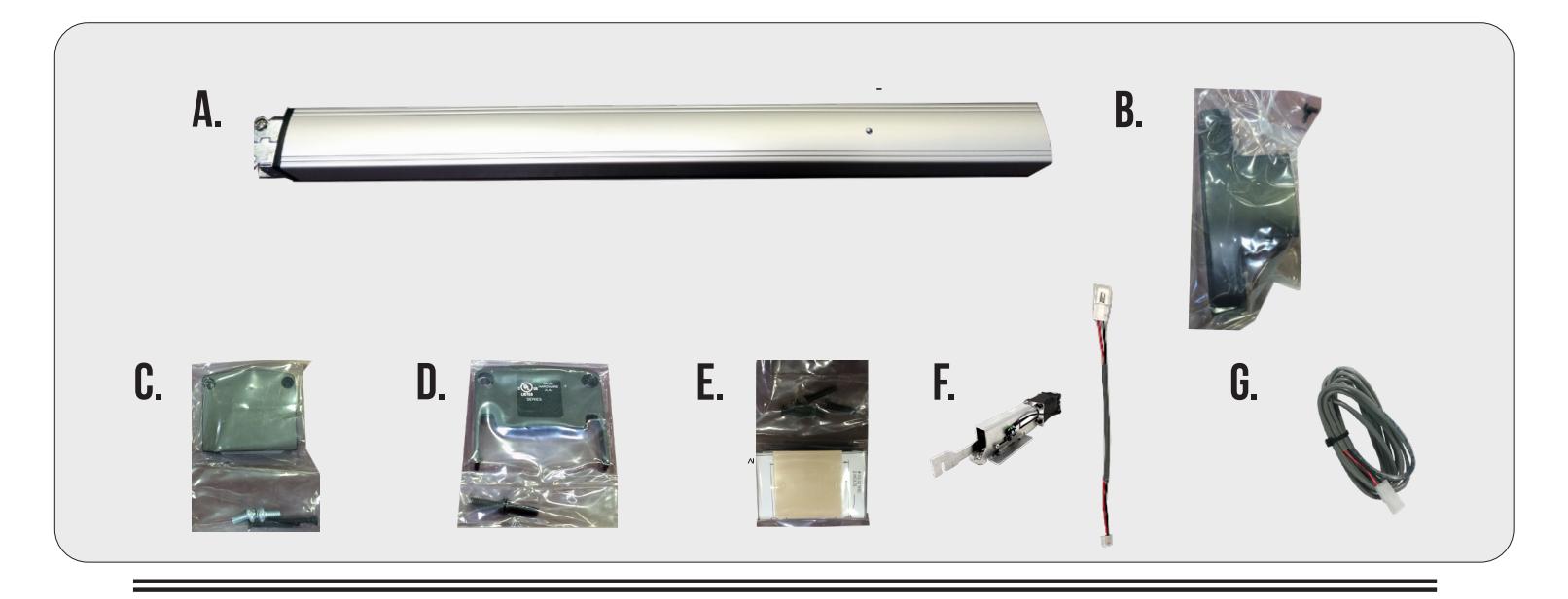
KIT INCLUDES | TOOLS REQUIRED
- A. Head Cover pack
- B. RIM Exit Device
- C. Hinge Stile End Cap pack
- D. Lock Stile End Cap pack
- E. Rim Strike pack
- F. MOTOR KIT Installed in exit device
- G. 1- 50944 Molex Pigtail
- H. 1- 50030 8' Lead w/ VD Connector
- • Cordless Drill
- • Needle nose Pliers
- • Measuring Tape
- • 1/2 Drill bit

TECHNICAL INFORMATION

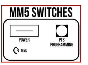
SETTING PUSH TO SET (PTS)
→ **IMPORTANT INFO** ← MAKE SURE TO SET PTS BEFORE FINISHING INSTALLATION
- STEP 1 - To enter PTS mode: Depress MM5 button & apply power. The device will emit 1 SHORT beep. The device is now in PTS mode.
- STEP 2 - While depressing the push pad, apply power. (i.e. presenting the credential to the reader).
- STEP 3 - Continue to keep pad depressed, the device will emit 1 LONG Beep. After the beep has stopped, release the pad and now the adjustment is complete. test the new location, If not to your liking repeat the 3 steps.
TROUBLESHOOTING & DIAGNOSTICS
| BEEPS | EXPLANATION | SOLUTION |
|---|---|---|
| 2 Beeps | Over Voltage | > 30V unit will shut down. Check voltage & adjust to 24 V. |
| 3 Beeps | Under Voltage | < 20V unit will shut down. Check voltage & adjust to 24 V. |
| 4 Beeps | Failed Sensor | Verify all 3 sensor wires are installed correctly. Replace sensor if problem persists by contacting office. |
| 5 Beeps | Retraction or dogging failure | After 1st fail: 5 beeps then immediately attempts to retract again. After 2nd fail: 5 beeps with pause in-between for 30 seconds then device attempts to retract again. After 3rd fail: 5 beeps every 7 minutes, device will not attempt to retract. To Reset: Depress bar for 5 seconds at any time. |

Electrified Exit Device
RIM PANIC

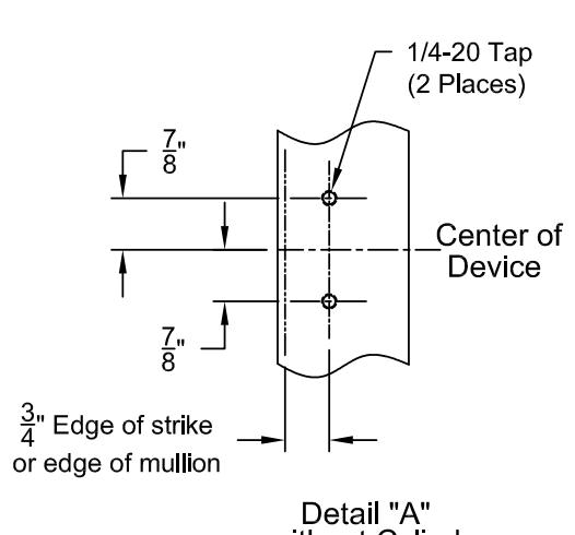
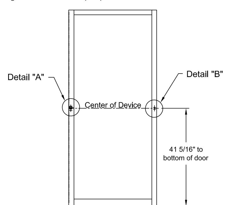
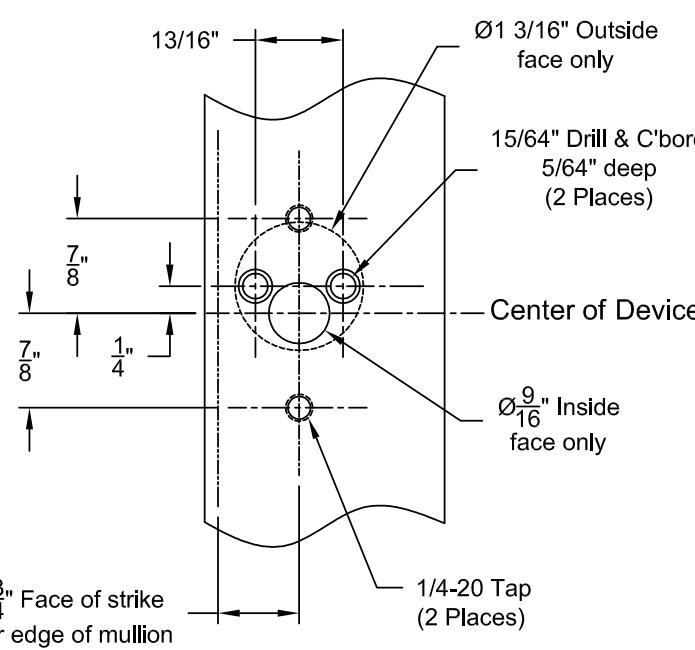
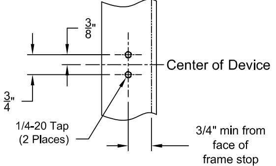
Installation Template All prep is shown on interior side of the door, except where noted. Right hand door shown. (LHR)

STEP 1 - MOUNT EXIT DEVICE

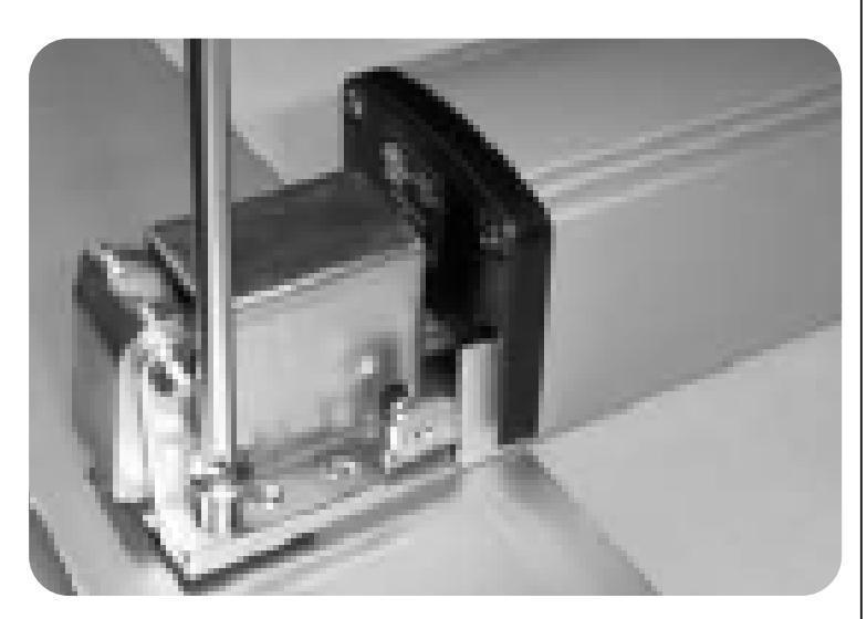
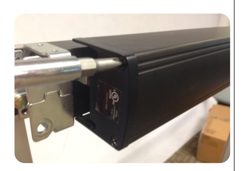
A. INSTALL THE STILE MOUNTING BRACKET WITH 2 EA. 1/4-20 X 1/2 PAN HEAD SCREWS. LEAVE SPACE TO CAPTURE THE BASE OF THE DEVICE. (SEE NEXT SLIDE)
B. SLIDE THE END OF BASERAIL UNDERNEATH THE MOUNTING BRACKET.
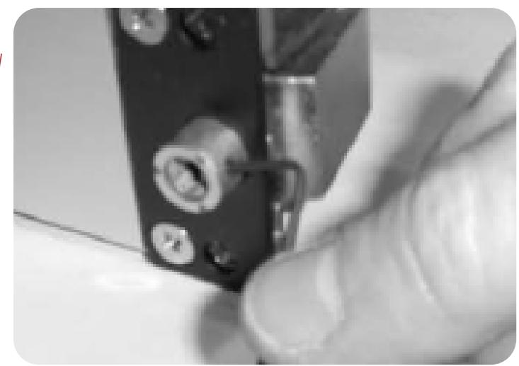
OPTIONAL STEP - INSTALLING CYLINDER
A. INSTALL TRIM CYLINDER TAIL PIECE SO THAT IT IS SLIGHTLY BELOW THE FACE AFTER MOUNTING.
INSTALL KEY CYLINDER USING MOUNTING SCREWS SUPPLIED WITH CYLINDER. (SCREWS MAY NEED TO BE SHORTENED.)

B. -FOR NIGHT LATCH, LEAVE SET SCREW IN PLACE. -HOLD BACK FUNCTION IS DESIRED, REMOVE THE SET SCREW TO ALLOW ADDITIONAL ROTATION OF CYLINDER TAILPIECE.
STEP 1B - CONTINUED
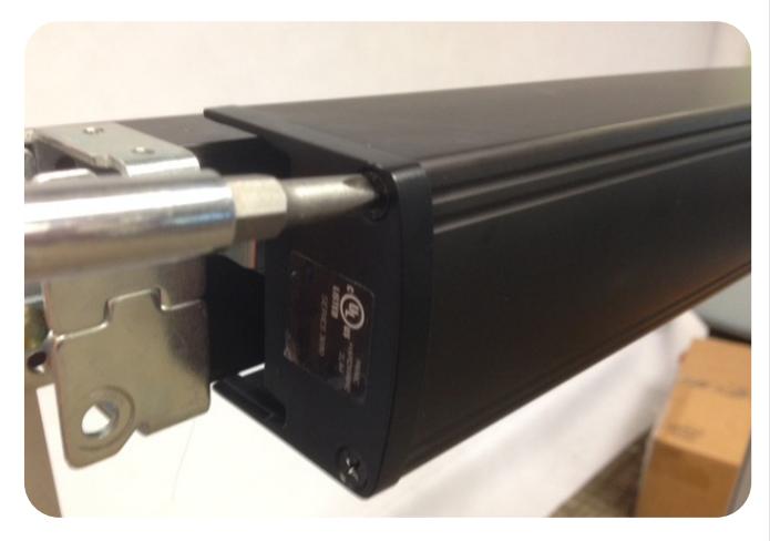
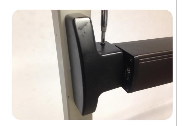
A. ATTACH HEAD OF DEVICE TO STILE WITH 2 EA. 1/4-20 X 3/4 " SCREWS. TIGHTEN SCREWS ON THE HEAD AND BASE OF THE DEVICE.
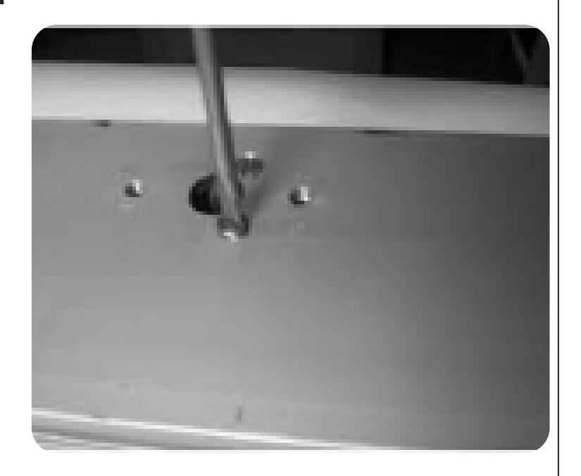
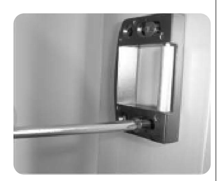
STEP 2 - DRILL WIRE CHASE
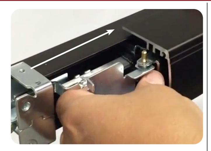
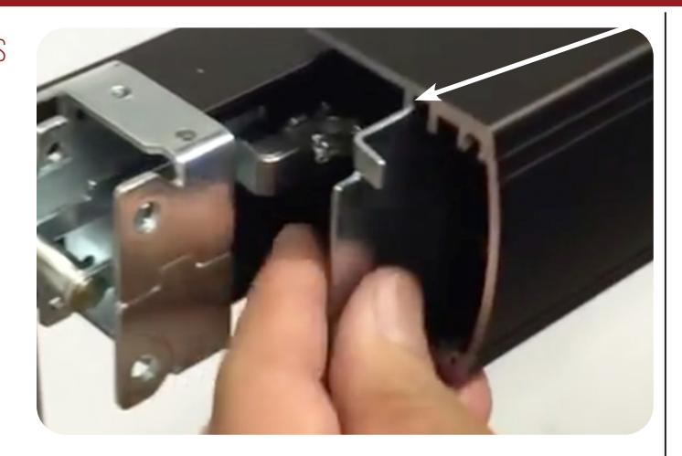
A. REMOVE LOCK STILE END CAP.
6

Slide push pad off of baserail. B.
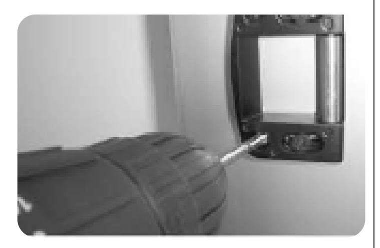
Drill the hole for our 2 pin power lead in-between the 2 mounting screws. C.
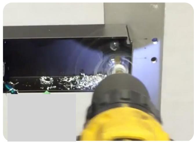
Feed the 2 pin power lead into the hole and connect to our MM4 module. Also, make sure to clean out any debris left. D.
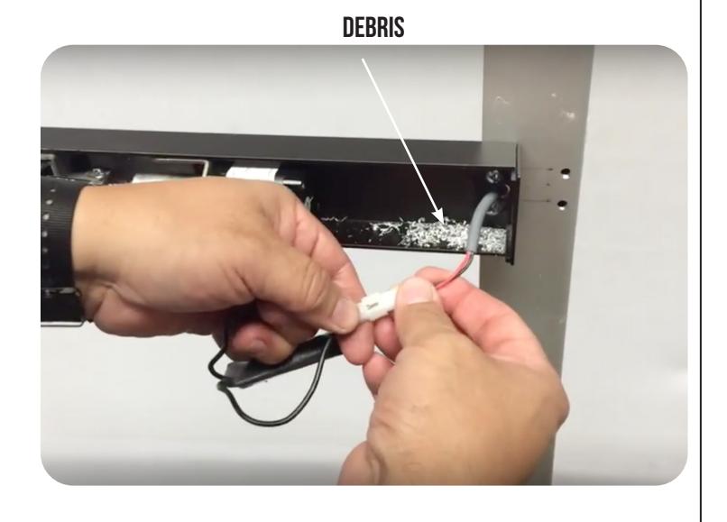
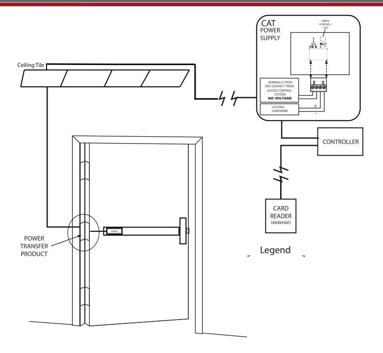
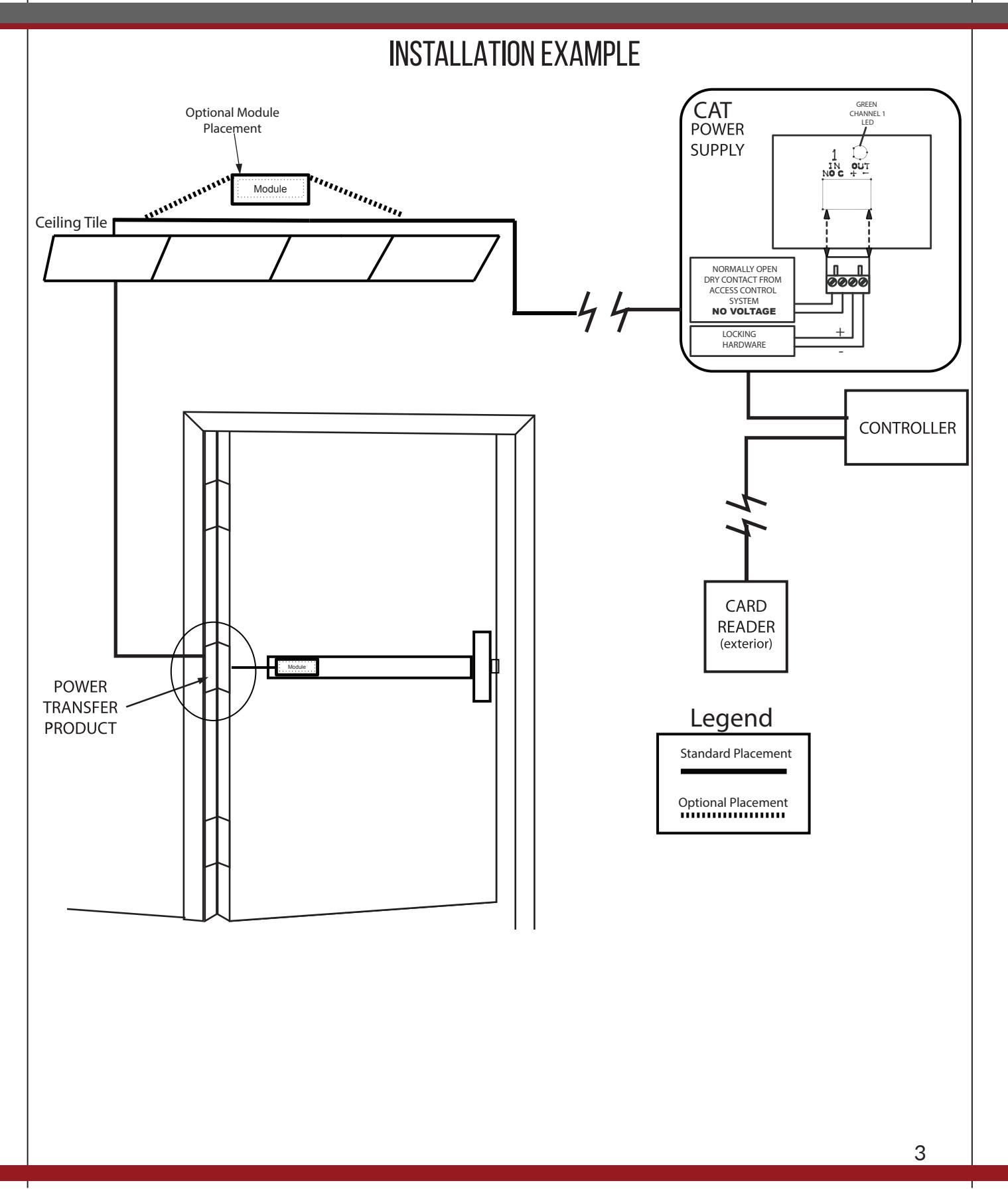
Note: Depending on where your power transfer is; next you would fish the other side of the power lead we connected to the MM4 and hook up to your incoming power. If you have a portable tester this would be a good time to test fire the motor.

Replace push pad, making sure the activating brackets and pins slide through the 3rd channel. E.
F. Reinstall the lock stile end cap.
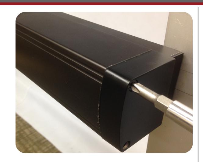
STEP 3 - Install Head & End Cap
A. Install head cover with 2 ea. 10-32 x 3/8 screws.

B. INSTALL HINGE STILE PUSH PAD COVER WITH 2 EA. 8-32 X 1 1/2" SCREWS. NOW YOU SET YOU LATCH RETRACTION ADJUSTMENT WITH OUR "PTS" TECHNOLOGY.
SEE PAGE #2
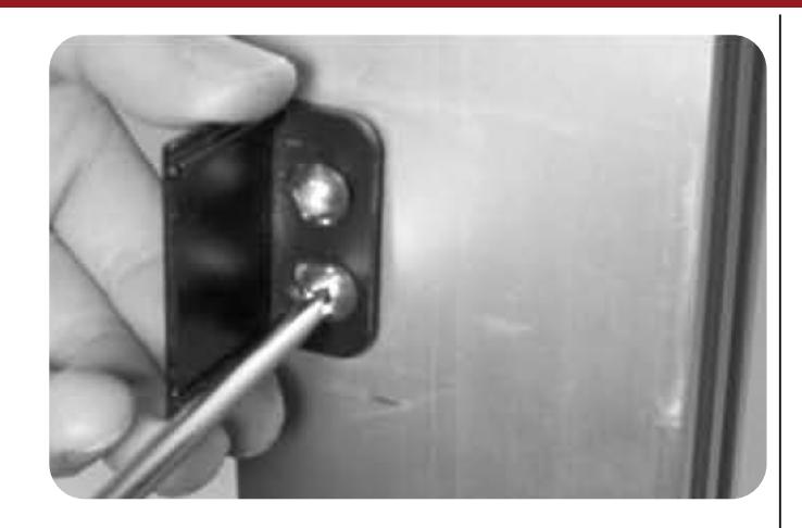
STEP 4 - INSTALL DOOR FRAME STOP
A. INSTALL THE ROLLER STRIKE WITH 2EA. #10-32 X 1 " SCREWS SO THE ROLLER IS FLUSH WITH THE FRAME STOP. (USE STRIKE SHIM FOR 5/16" STOPS.)
B. USING THE ROLLER STRIKE AS A TEMPLATE, DRILL AND TAP REAR MOUNTING HOLES. INSTALL REMAINING 10-32 X 1" MOUNTING SCREWS AND TIGHTEN ALL SCREWS.
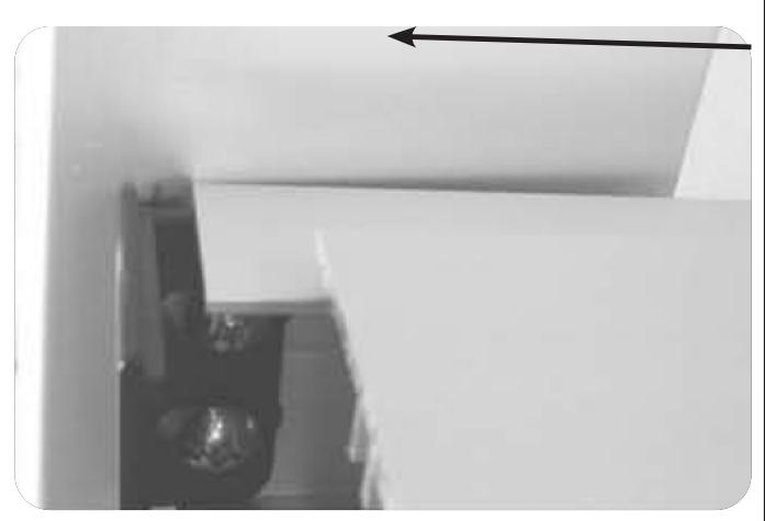
STEP 5 - Install Wear Strip

Cut wear strip to desired length. A.
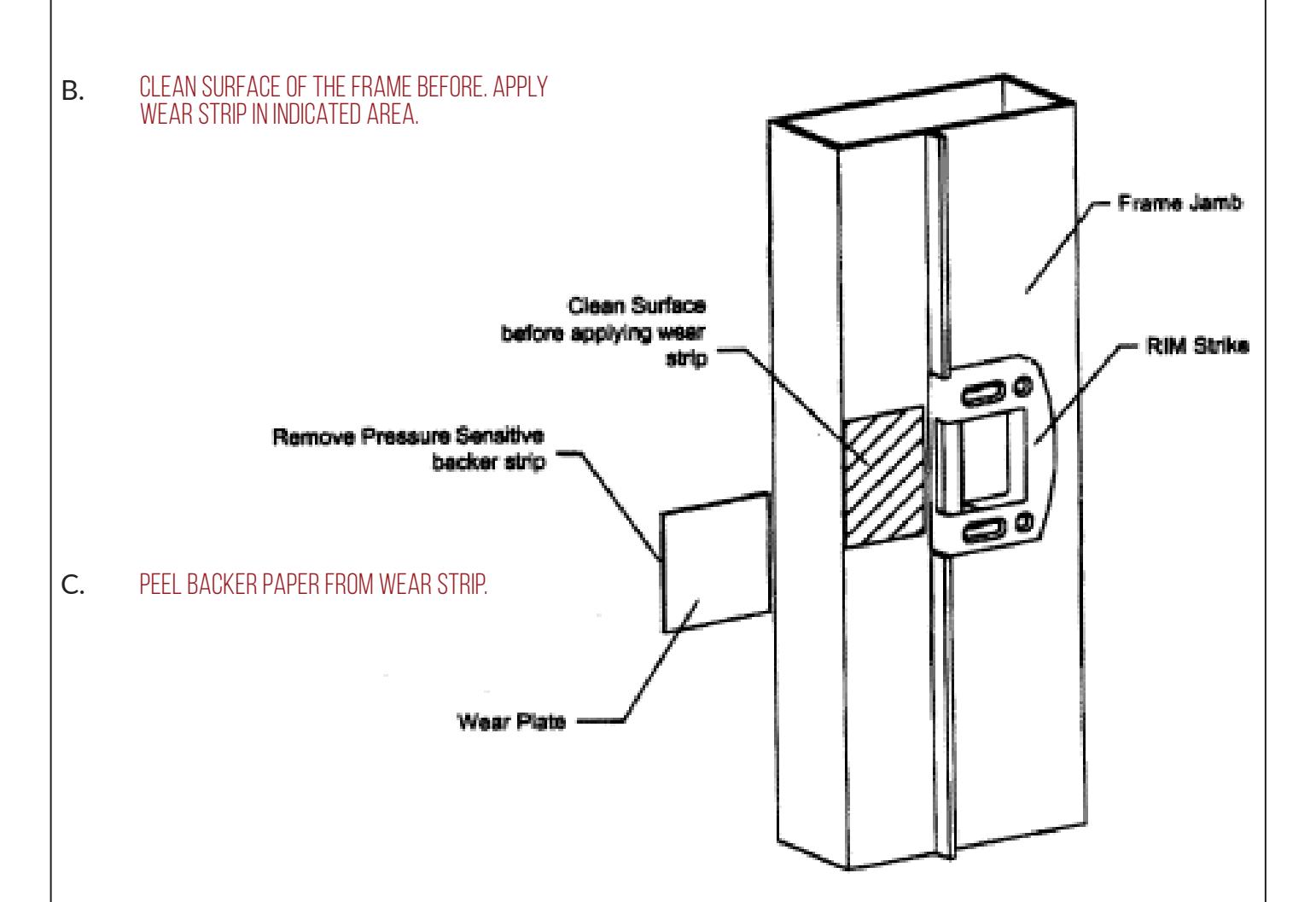
Apply wear strip flush to front of frame jamb in indicated area. D.
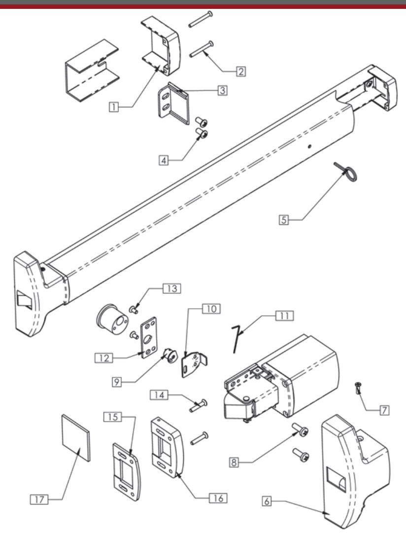
PD10 Parts Breakdown

| Reference | Quantity | ||
|---|---|---|---|
| Number | Description | Part Number | Per Device |
| 1 | Hinge Stile Push Bar End Cap | 30 | 1 |
| 2 | End Cap Screw | 802 | 2 |
| 3 | Channel End Cap | 33 | 1 |
| 4 | Hinge Stile Mounting Screws | 801 | 2 |
| 5 | Dogging Key | 819 | 1 |
| 6 | Center Cover | 40A | 1 |
| 7 | Cover Screw | 804 | 2 |
| 8 | LS Mounting Screws | 826 | 2 |
| 9 | Cylinder Cam | 9039 | 1 |
| 10 | Retractor | 35 | 1 |
| 11 | Allen Wrench | 825 | 1 |
| 12 | Cam Spacer Plate | 31 | 1 |
| 13 | Spacer Plate Screws | M817 | 2 |
| 14 | Stike Mounting Screw | 836 | 4 |
| 15 | Strike Shim | 17001423 | 1 |
| 16 | Strike Assy. | 17001A05 | 1 |
| 17 | UHMD Wear Strip | 17001288 | 1 |

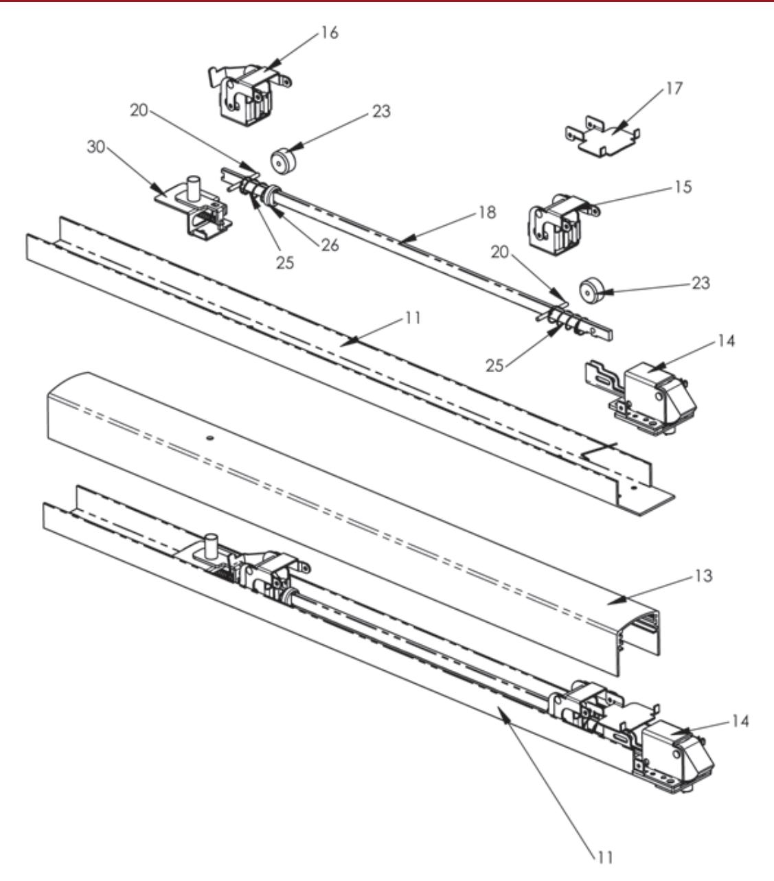
| Reference | Quantity | ||
|---|---|---|---|
| Number | Description | Part Number | Per Device |
| S1 | Hinge Stile Activating Bracket | 71 | 1 |
| S2 | Lock Stile activationg Bracket | 9034 | 1 |
| S3 | Push Bar Bracket | 15 | 1 |
| S4 | Push Bar Axle Pin | 16 | 2 |
| S5 | Roller Stop | 17 | 2 |
| S6 | Spring | 23 | 2 |
| S9 | Spring Cap | 24 | 1 |
| S10 | Activating Connecting Rod | 21 | 1 |
| S11 | Rim Latch Bracket Assy. | 9032 | 1 |
| S12 | Dogging Kit | 71 | 1 |