PD 10-M-CVR Installation Instruction
Open the original PDF document
View PDF

PD10-m-CVR

I N S E R T I n s t r u c t i o n s
The PD10-M-CVR is a storefront grade 1 exit device equipped with motor drive latch retraction. Retrofits Doromatic 1690 & First Choice 3690.
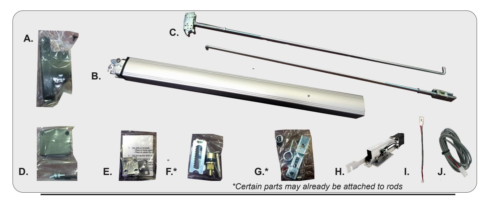
KIT INCLUDES | TOOLS REQUIRED
- A. Head Cover pack
- B. CVR Exit Device
- C. Concealed Vertical Rods
- D. Hinge Stile End Cap pack
- E. Strike pack
- F. Retractor & Pinion pack
- G. Traveler pack
- H. MOTOR KIT Installed in exit device
- I. 1- 50944 Molex Pigtail
- J. 1- 50030 8' Lead w/ VD Connector
- • Cordless Drill
- • Needlenose Pliers
- • Measuring Tape
- • 1/2 Drill bit


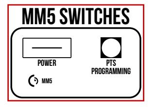
SETTING PUSH TO SET (PTS)
→ **IMPORTANT INFO** <</p>
MAKE SURE TO SET PTS BEFORE FINISHING INSTALLATION
- STEP 1 - To enter PTS mode: Depress MM5 button & apply power. The device will emit 1 SHORT beep. The device is now in PTS mode.
- STEP 2 - While depressing the push pad, apply power. (i.e. presenting the credential to the reader).
- STEP 3 - Continue to keep pad depressed, the device will emit 1 LONG Beep. After the beep has stopped, release the pad and now the adjustment is complete. test the new location, If not to your liking repeat the 3 steps.
TROUBLESHOOTING & DIAGNOSTICS
| BEEPS | EXPLANATION | SOLUTION |
|---|---|---|
| 2 Beeps | Over Voltage | > 30V unit will shut down. Check voltage & adjust to 24 V. |
| 3 Beeps | Under Voltage | < 20V unit will shut down. Check voltage & adjust to 24 V. |
| 4 Beeps | Failed Sensor | Verify all 3 sensor wires are installed correctly. Replace sensor if problem persists by contacting office. |
| 5 Beeps | Retraction or dogging failure | After 1st fail: 5 beeps then immediately attempts to retract again. After 2nd fail: 5 beeps with pause in-between for 30 seconds then device attempts to retract again. After 3rd fail: 5 beeps every 7 minutes, device will not attempt to retract. To Reset: Depress bar for 5 seconds at any time. |

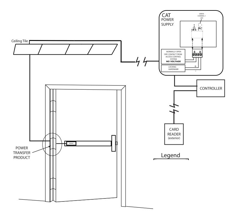
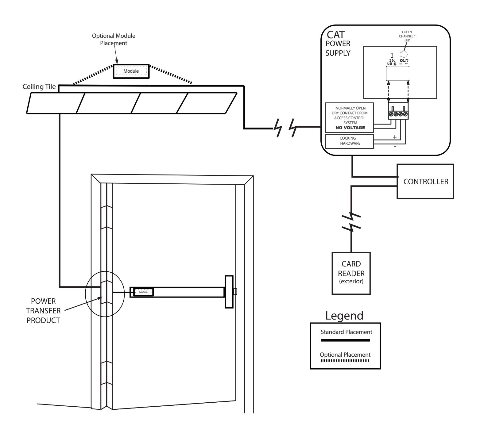
Electrified Exit Device
Installation Example

Concealed Vertical Rod For Bottom Rod Latch Installation Template All prep is shown on interior side of the door, except where noted. Right hand door shown. (LHR) Center of Device Small Radius Detail "D" 3/4" min from 1/4-20 Tap face of 2 Places frame stop Detail "B" .196 (#9) Drill through C'Sink 82° to 3/8" dia " Min from 2 Places door stop Detail "D" Top Latch Cutout inside face only! Detail "B" Detail "A" Detail "E" Center of Device .196 (#9) Drill through C'sink 82° to 3/8" dia 2 Places Center of Panic — " (2 Plcs) 40 5/8" .520 (2 Plcs) " Min from door stop Detail "A" 3/4" min from door stop Ø13/16" — Exterior side of door. Detail "C" Detail "C" for Rod Latch " Drill & C'bore Ø<u>9</u>" Ream 5/64" Deep 1/4-20 Tap (2 Plcs) (2 Plcs) 1/4-20 Tap (2 Plcs) Center of Panic Center of Device Detail "E" with Cylinder Detail "E"
without Cylinder

STEP 1 - Install Vertical Rods
(Rods are factory preset for door height of 83 3/16 and a cylinder location of 41 5/16- see page 9 for additional details.)
Install top latch mechanism using 2 ea. #10-31X1/4 screws. A.
Affix bent end of rod on door using rod bushing with "E" ring. B.
Install bottom rod assembly in the same manner as above. C.
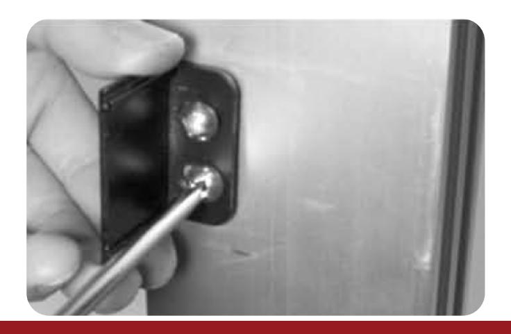
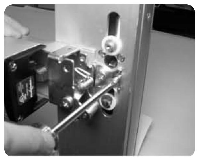
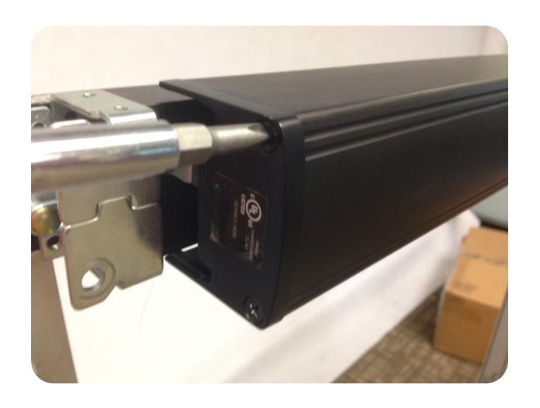
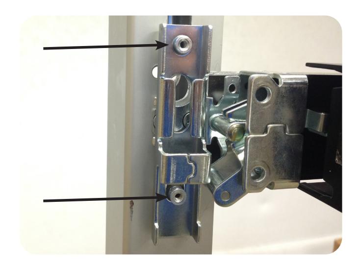
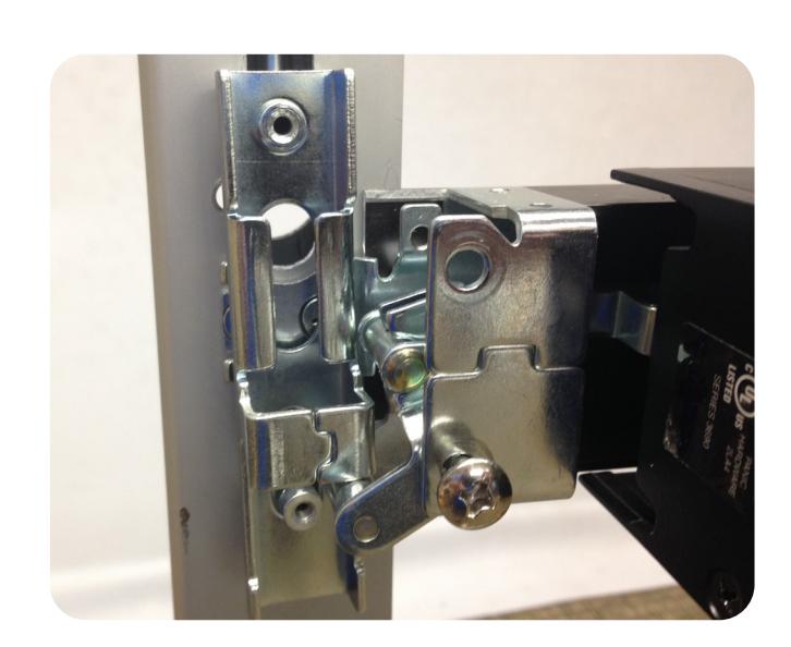
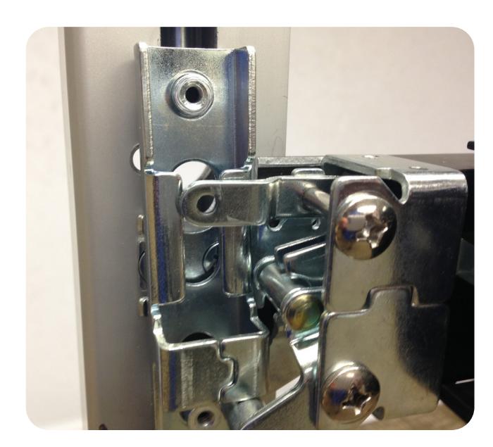
STEP 2 - Mount Exit Device
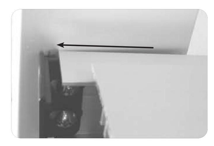
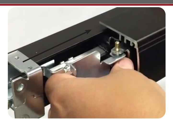
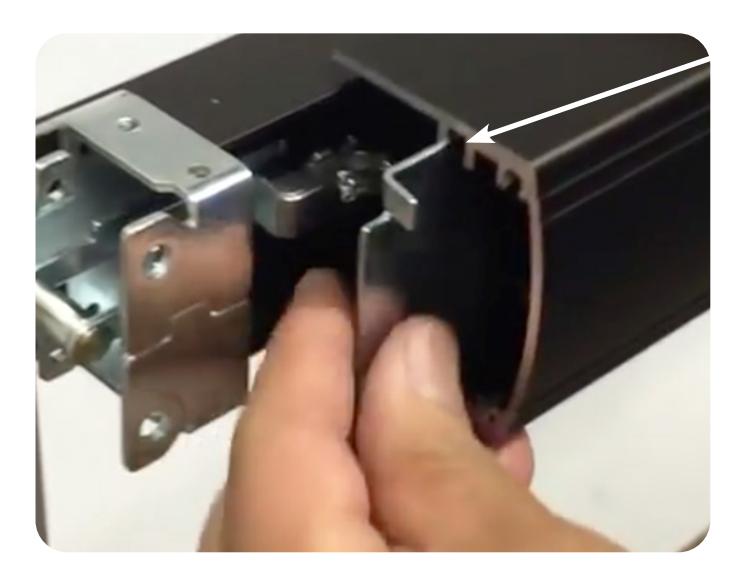
Install the stile mounting bracket with 2 ea. 1/4-20 x 1/2 pan head screws. Leave space to capture the base of the device. (See next slide) A.

Slide the end of baserail underneath the mounting bracket. B.
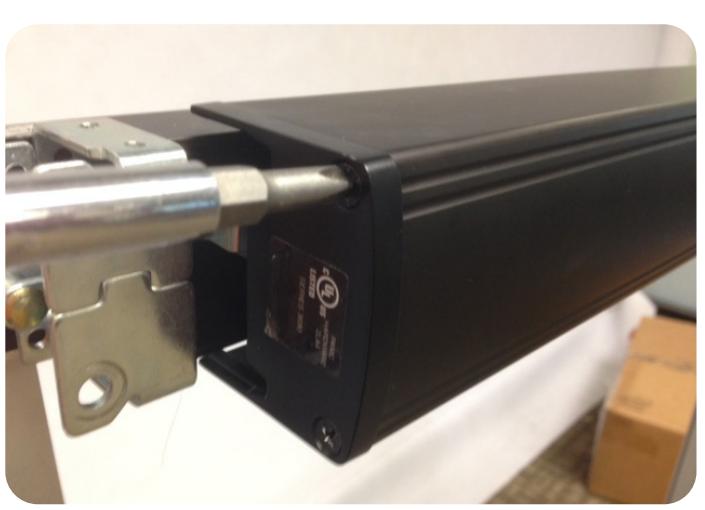
Attach head of device to stile with 2 ea. 1/4-20x1/2 flat head screws. Tighten screws on the head and tail of the device. C.
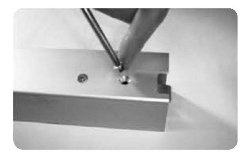
STEP 3 - Drill Wire Chase
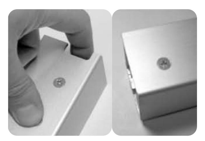
Remove lock stile end cap. A.

Slide push pad off of baserail. B.
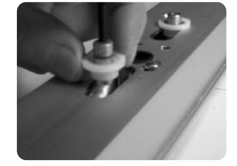
Drill the hole for our 2 pin power lead inbetween the 2 mounting screws. C.
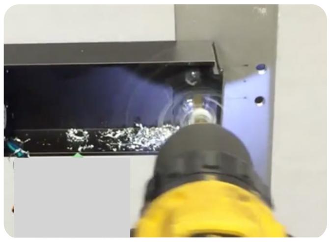
Feed the 2 pin power lead into the hole and connect to our MM4 module. Also, make sure to clean out any debris left. D.
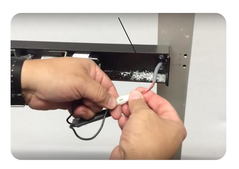
Note: Depending on where your power transfer is; next you would fish the other side of the power lead we connected to the MM5 and hook up to your incoming power. If you have a portable tester this would be a good time to test fire the motor.

Replace push pad, making sure the activating brackets and pins slide through the 3rd channel. E.
F. Reinstall the lock stile end cap.
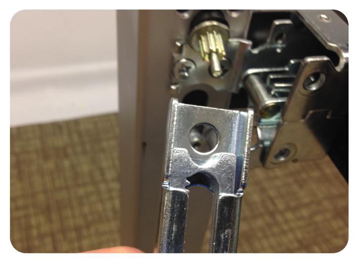
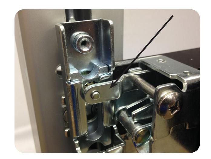
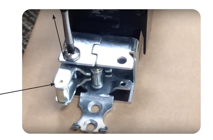
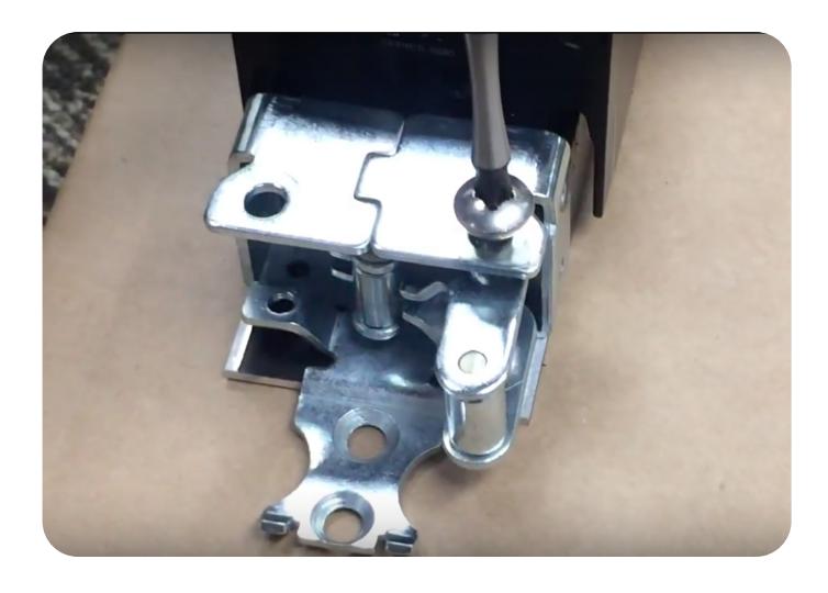
STEP 4 - Attach Vertical Rods
Before installing the traveller. Remove Axle screw, allowing the lifting arm to relax and move out of the way. A.
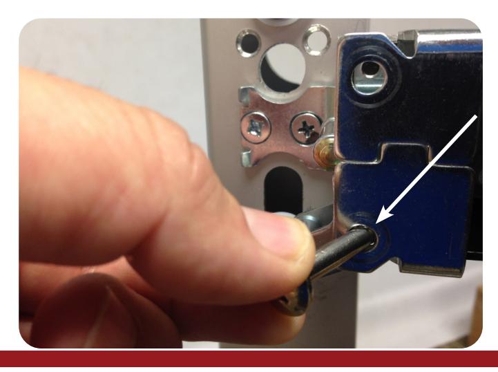

Install Traveller onto the bent end of the vertical rods. B.
Re-install Axle screw and tighten. C.
Install Pinion support bracket and tighten retainer screw. D.

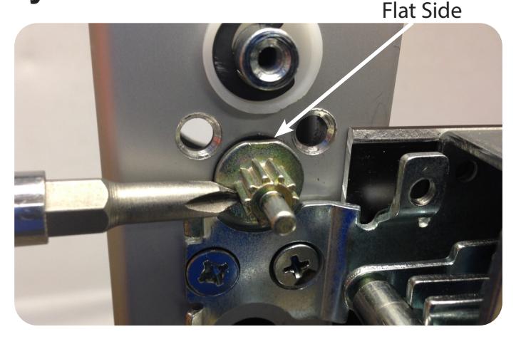
Optional STEP - Installing Cylinder
Place Pinion with black cylinder bushing into the door with the cylinder tail piece sliding into the back of the pinion. A.
Flat side of pinion facing up.
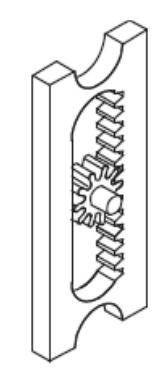
Add Retractor and Traveller lift bracket. Pick placement of pinion depending on desired function. B.
Reinstall Axle screw and tighten. C.

Install Pinion support bracket and tighten retainer screw. D.
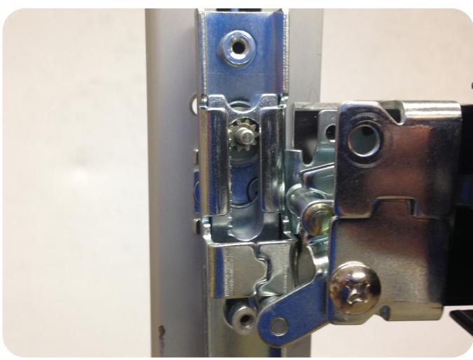
STEP 4 - Continued
-Check Top Rod operation. A.
When push pad is depress fully, top latch should open and allow top strike to pass, and swing freely.
-Check Bottom Rod operation.
The bottom latch should not protrude more than 1/16 inch below the bottom of the door when the push pad is depressed.
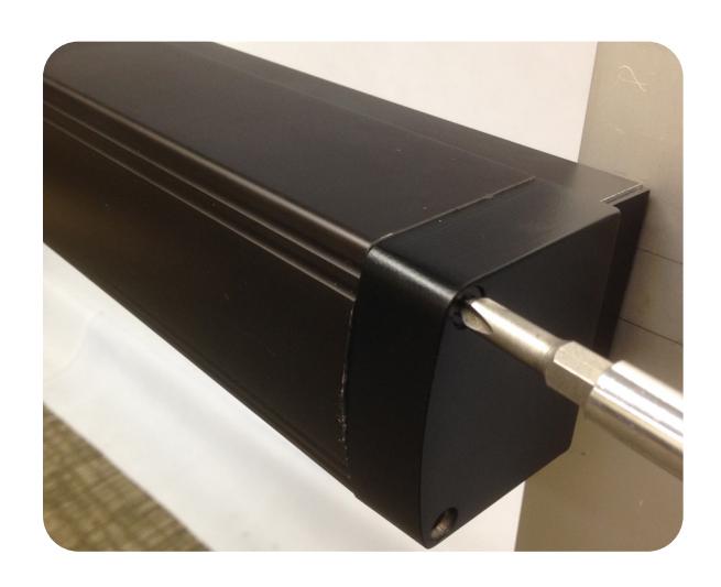
B. Install head cover with 2 ea. 10-32 x 3/8 screws.
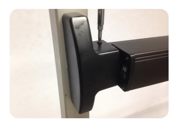

Install hinge stile push pad cover with 2 ea. 8-32 x 1 1/2" screws. Now you set you latch retraction adjustment with our "PTS" technology. See page #2 C.
Optional STEP - How to change hand-
Remove the Axle screw and lifting arm. A.
Lifting arm.
Flip the lifting arm to the other side of the assembly. Re-install Axle screw and tighten. B.

|
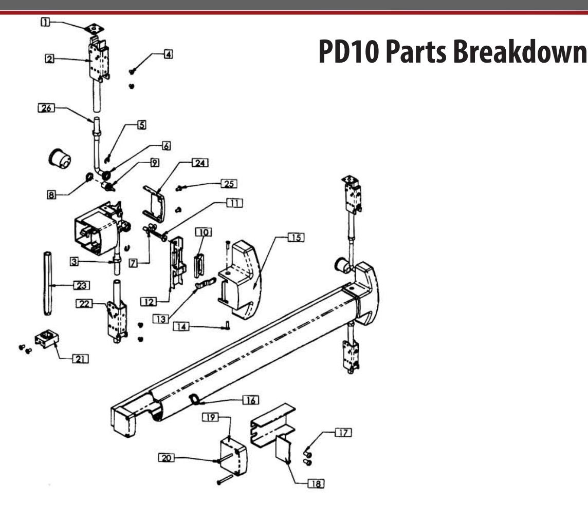
Reference
Number |
Description | Part Number |
Quantity
Per Device |
|---|---|---|---|
| 1 | Top Strike Kit - SS | 9038 | 1 |
| Consists of: | |||
| Top Strike (1 ea.) | 16001238 | ||
| Strike Shim (3 ea.) | 16001118 | ||
| 2 | Top Latch Assembly | 42 | 1 |
| 3 | Jamb Nut | 806 | 2 |
| 4 | Latch Housing Screw | 811-CL, 811-BR | 4 |
| 5 | Retaining E-Ring | 809 | 2 |
| 6 | Rod Bushing | 810 | 2 |
| 7 | Lock Stile Mounting Screw | 816 | 2 |
| 8 | Cylinder Bushing | 16001004 | 1 |
| 9 | Pinion | 16001007 | 1 |
| 10 | Retractor | 16001003 | 1 |
| 11 | Axle Screw | 3 | 1 |
| 12 | Traveler | 16001098 | - 1 |
| 13 | Pinion Support Bracket | 821 | 1 |
| 14 | Cover Screw | 804 | 2 |
| 15 | Center Case Cover | 40 | 1 |
| 16 | Dogging Key | 819 | 1 |
| 17 | Hinge Stile Mounting Screw | 801 | 2 |
| 18 | Channel End Cap | 33 | 1 |
| 19 | Hinge Stile Push Bar End Cap | 30 | 1 |
| 20 | End Cap Mounting Screw | 802 | 2 |
| 21 | Weighted Latch Guide w/ Screws | 77 | 1 |
| 22 | Bottom Latch Assy - Spring | 45 | 1 |
| 23 | Bottom Latch Assy - Weighted | 76 | 1 |
| 24 | Lock Stile End Cap | 50 | i |
| 25 | LS End Cap Mounting Screw | 838 | 2 |
| 26 | Vertical Rod w/ locking nut | 16001015 | 2 |


|
Reference
Number |
Description | Part Number |
Quantity
Per Device |
|---|---|---|---|
| S1 | Axle Pins | 14 | 2 |
| S3 | Spring | 23 | 1 |
| S4 | Spring Cap | 24 | 1 |
| S5 | Roller Stop | 17 | 2 |
| S7 | Crank Bracket Assy. | 9040 | 1 |
| S8 | Activating Connecting Rod | 21 | 1 |
| S9 | Lock Stile Activating Bracket | 9034 | 2 |
| S11 | Push Bar Bracket | 15 | -1 |