Operating and Installation Instructions Alarm Interface 871084-2
Open the original PDF document
View PDF

Installation and Operating Instructions Alarm Interface 871084-2
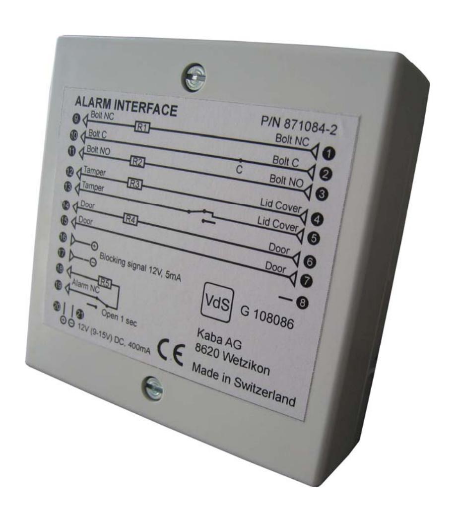

Description
The Alarm Interface is an integrated blocking device in a tamper proof container, which can be connected to La Gard locks and to Alarm Systems. All La Gard locks with the option of external battery connections can be connected via the battery port to the Alarm Interface. Alarm Systems are coupled to the lock via the Alarm Interface.
Function
Silent Duress signals from the lock activate a relay in the Interface triggering alarm functions in the Alarm System.
The lock can be disabled via remote signal. Remote Disable signals from Alarm Systems are conducted to the lock, disabling lock functions. The extent of disabled lock functions depends on the type of lock setup.
Locks
The Alarm Interface can be used with the following locks:
- 3040 and 6040 Deadbolt locks
- 4100 and 4300 Swingbolt locks
- 2441 and 6441 Override locks
Bolt Sensors
Lock bolt sensors can be integrated with the Alarm Interface. The 6040 Deadbolt and 4300 Swingbolt Audit locks and the 2441 and 6441 Override locks require an external bolt sensor.
Setup Preparations
The Alarm Interface should have resistors R1 to R5 populated, before setup, if the connections are to be used.
Setup – Alarm Interface to Lock
- 1. Connect the Interface cable to the battery port of the lock
-
2. Connect the bolt sensor cables to the Alarm Interface:
- a. Normally closed cable to pin 1
- b. Common cable to pin 2
- c. Normally open cable to pin 3
- 3. Connect door sensor leads to pins 6 & 7.

Setup – Alarm Interface to Alarm System
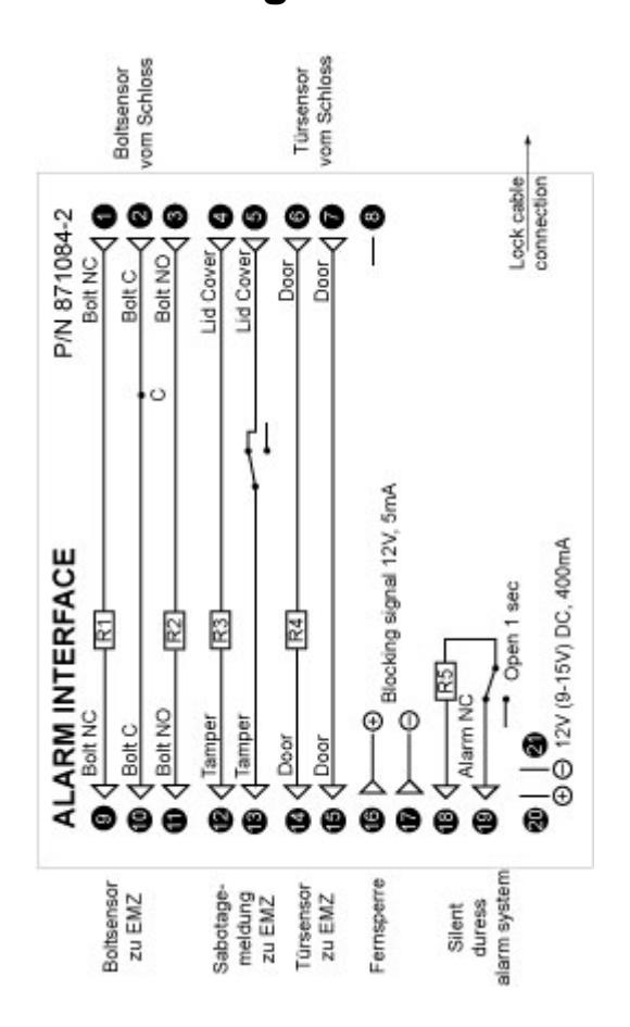
- 1. The bolt arm/ disarm connections are made to pins 9, 10 & 11. Pins 9 & 10 are normally closed (NC). Pins 10 & 11 are normally open (NO). When using only 2 wires short either R1 or R2 (NC connection) to "C" using a resistor.
- 2. The tamper pins 12 & 13 are connected through the normally closed (NC) switch.
- 3. The door arm/ disarm connections are made to pins 14 & 15.
- 4. The Remote Disable connections are made to pins 16 & 17 with 12 V, 5 mA.
- 5. The Silent Duress signal from the lock connected through pins 18 & 19 triggers the relay switch for 1 second.
Setup – Test
Test the system's functioning before activating the alarm system:
Bolt sensor
- 1. Connect the lock to the Alarm Interface.
- 2. Close lock pins 1 & 2/ 9 & 10 are closed.
- 3. Operate lock; Enter opening code.
- 4. Pin 2 & 3/ 10 & 11 are closed
Remote disable
- 1. Activate the Remote Disable (12 V DC, 5 mA) to pins 16 & 17.
- 2. Operate lock; Enter opening code. Lock signals beeps 6 times. Lock does not open as long as the Remote Disable is activated.
Silent duress
- 1. Operate lock; Enter Silent Duress code Last digit ± 1. Relay switch opens 1 second.
- 2. Pins 18 & 19 open 1 second.

Circuit diagram

Technical Specifications
| Size | 83 x 83 x 25 mm |
|---|---|
| Input power (Lock and Interface) 12 V DC (9 – 15 V), 400 mA (5 mA on standby) | |
| Voltage Ripple | 1 V at 12 V operating voltage |
| Remote Disable | 12 V DC (9 – 15 V), 5 mA |
| Operating Temperature | - 10°C <> + 55°C |
| Environment class (VdS) | II |
| IP Protection | IP3x |