Olympus Lock – Padlockable Cam Lock 820S 820LC Installation Instructions
Open the original PDF document
View PDF820S / 820LC
IMPORTANT:
- 1. It is highly recommended that you install the cam/prong driver and lock cylinder into the lock body and cycle to the locked position before assembling cam, cam shifter and stop pin onto the back of the lock.
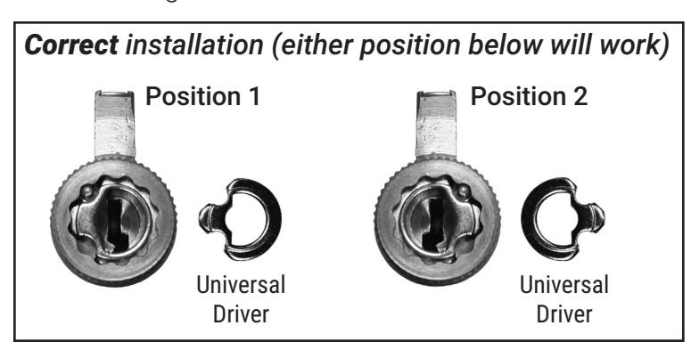
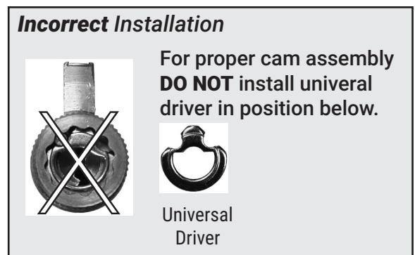
- 2. For lock to function correctly, you must install the universal driver into back of cylinder according to the directions below.
Typical Installation
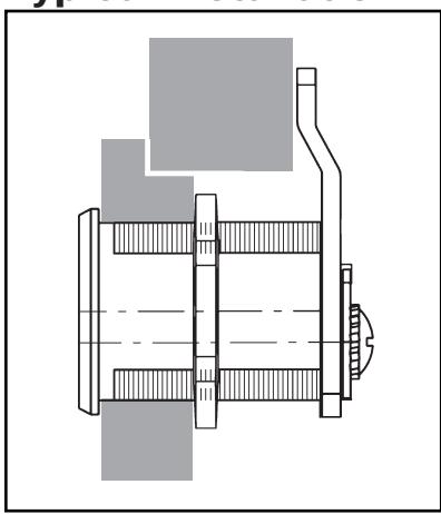
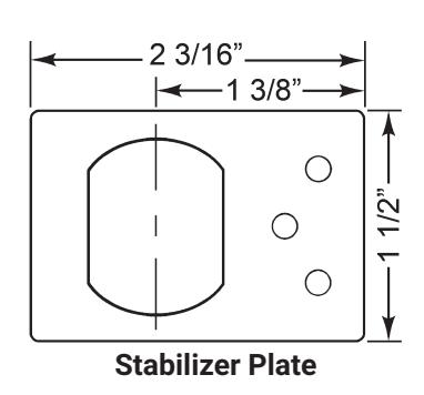
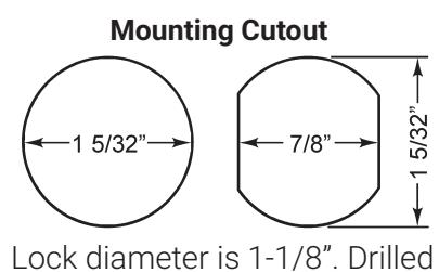
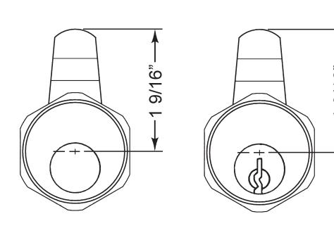
Lock diameter is 1-1/8". Drilled hole should be slightly larger.
|
Title
Installation instructions for 820 series cam lock |
||||
|---|---|---|---|---|
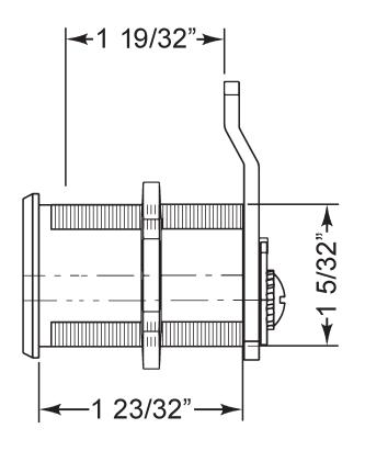
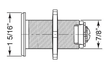
| Series | Barrel Length | Bolt type | Mounting | Revision Date |
| 820 | 1-23/32" | Cam lock | Surface | 9/2014 |

820S / 820LC
Assembled with vertical long cam 720-3-2 or extra long 3" cam 720-3-4
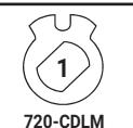
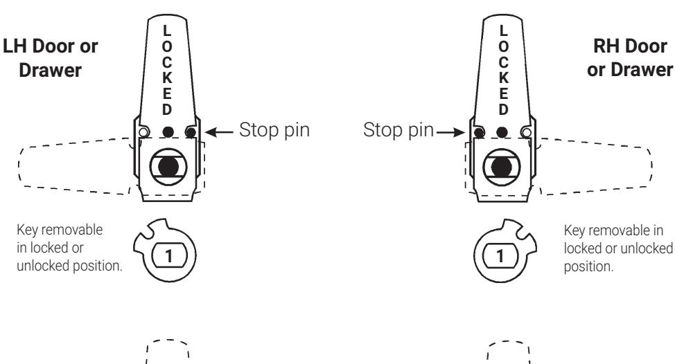
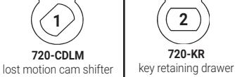
720-CDLM lost motion cam shifter (non-key-retaining)
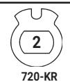
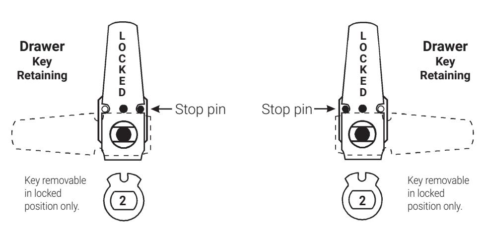
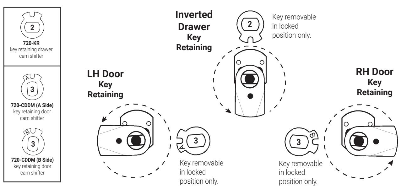
720-KR key retaining drawer cam shifter
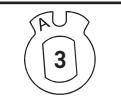
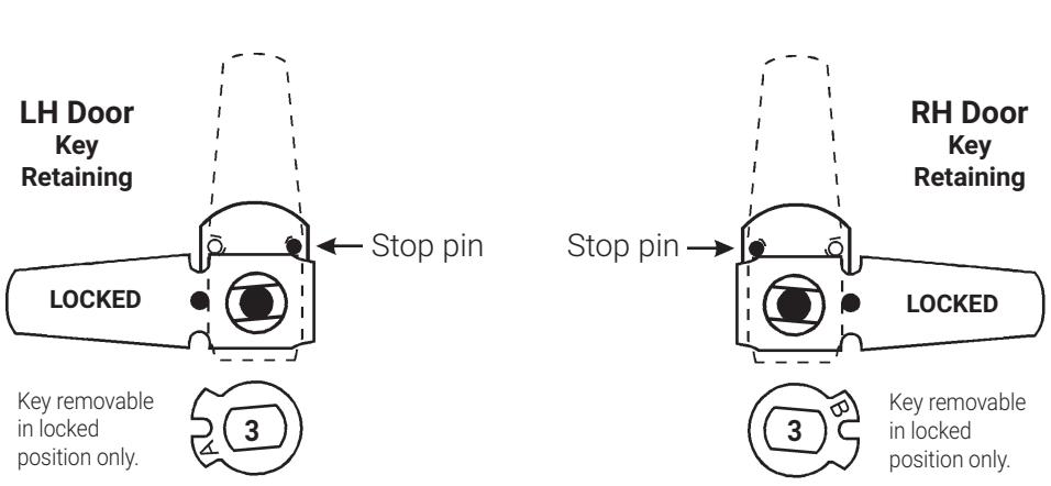
720-CDDM (A Side) key retaining door cam shifter
key retaining door cam shifter
IMPORTANT! If your cam has a brass pin between the two notched cut outs use these instructions, otherwise see page 3.

820S / 820LC
Assembled with vertical long cam 720-3-2 or extra long 3" cam 720-3-4
(non-key-retaining)

720-CDDM (A Side) key retaining door cam shifter cam shifter
3
720-CDDM (B Side)
key retaining door cam shifter
IMPORTANT! If your cam has a brass pin on the bottom of the cam use these instructions, otherwise see page 2.
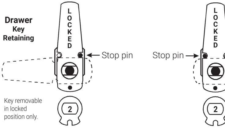
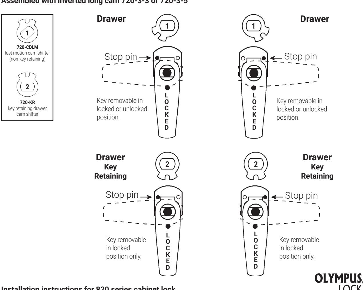
Drawer
Key
Retaining
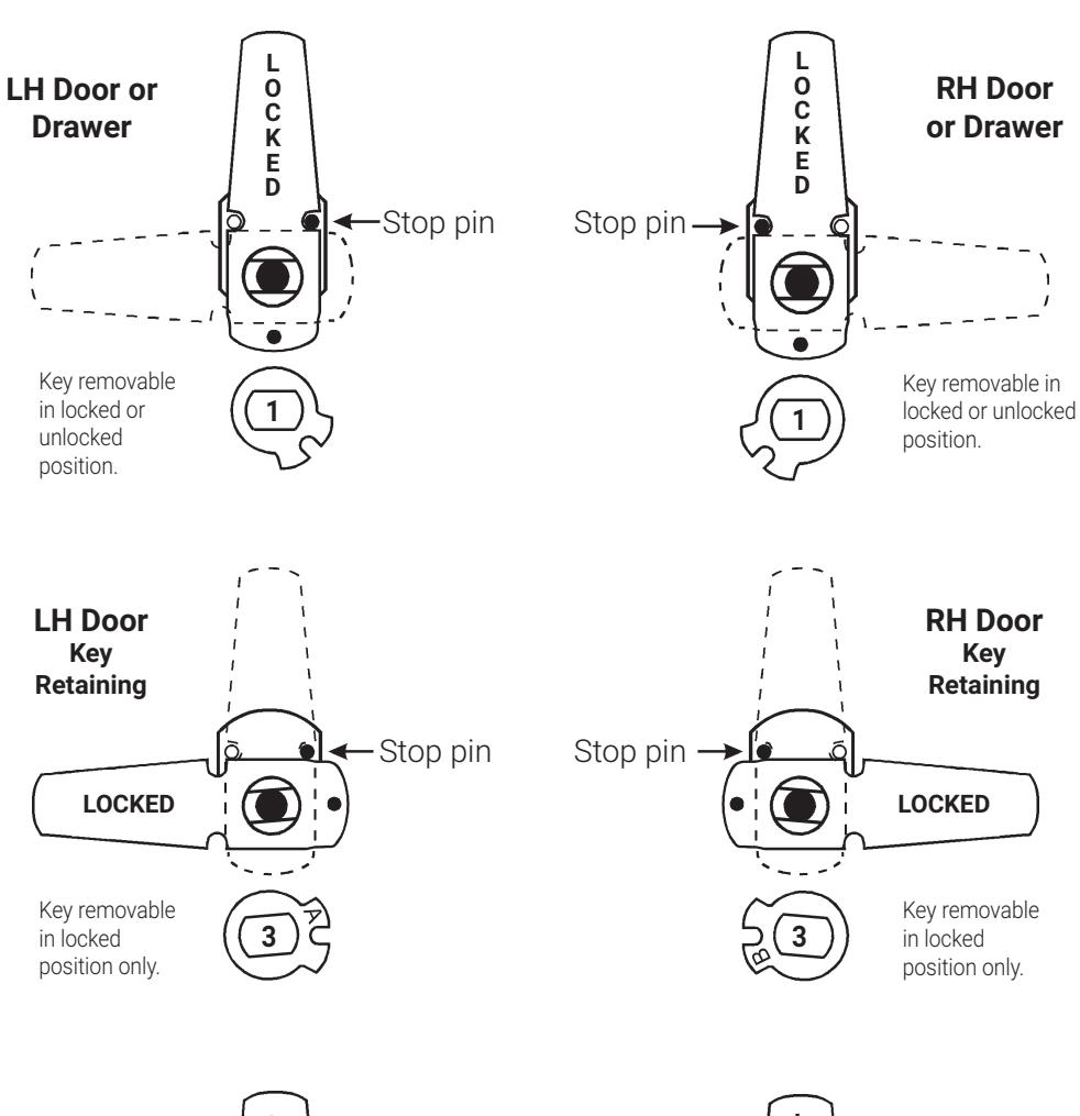
Key removable
position only.
in locked
Assembled with short cam 720-3-1 820S / 820LC
Assembled with inverted long cam 720-3-3 or 720-3-5