Olympus Lock FC10 Series Installation Instructions
Open the original PDF document
View PDFFC10 Series
Pin Tumbler File Cabinet Lock Kit Assembly and Installation Instructions
Recommended Tools (Fig. 1)
Flat Bladed Screwdriver Phillips Screwdriver Narrow Jawed Channel Lock Pliers
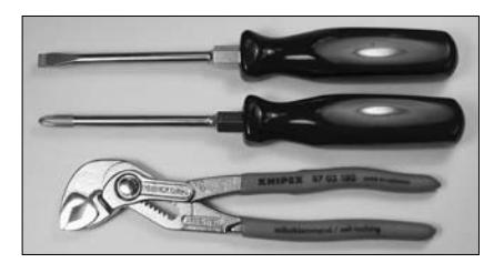
Figure 1
Parts – In Order of Assembly (Fig. 2)
- a. Lock Housing
- b. Outer Bezel Ring
- c. Inner Spacer Ring
- d. Nut Retaining Washer
- e. Brass Nut
- f. Inner Cam Stop
- g. Cam h. Outer Cam Shifter
- i. Retaining Screw
- j. Connecting Link
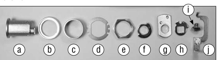
Figure 2
- 1. The file cabinet should be prepared for accepting the lock by having a partially punched ¾ inch D-D hole and an internal gang bar installed down the right side of the cabinet. Using your screwdriver and pliers remove the slug from the partially punched hole.
- 2. Slide the outer bezel ring onto the lock housing and insert the housing through the D-D hole. (Fig. 3)
- 3. From the inside install the inner spacer ring, nut retaining washer and brass nut. Do Not Over Tighten Once the nut is firm bend one of the tabs on the nut retaining washer against a flat side of the nut to hold it in place. (Fig. 4)
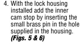
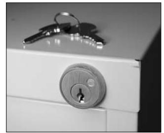
Figure 3 Figure 4
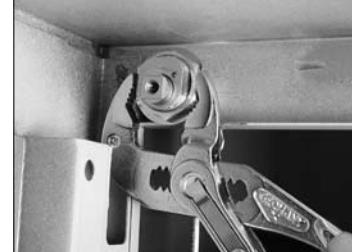
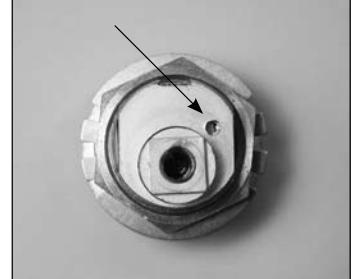
Figure 5
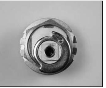
Figure 6
- 5. The cam is installed with the side labeled "OUT" facing the rear of the lock. The brass pin travels freely within the notched side of the inner cam stop. (Fig. 7)
-
6. The outer cam shifter can provide two different functions depending on how it is installed.
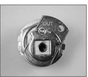
- • "Non Key Retaining" function: allows the key to be removed in both the locked and unlocked position and the shifter is installed so the brass pin on the cam travels in the long outer notch of the shifter labeled "LM" for lost motion. (Fig. 8)
- • "Key Retaining" function: allows you to remove the key in the locked position only and the brass pin of the cam fits into the small inner notch of shifter labeled "KR". (Fig. 9)
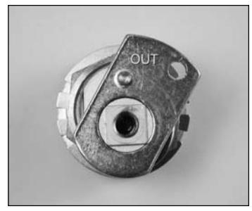
Figure 7
Please Note: To correctly synchronize the lock it must be assembled without a key inserted and the cam pointing up in the locked position. (Figs. 8 & 9) Finally, all is secured using the supplied retaining screw.
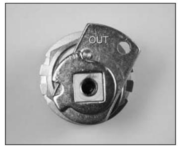
Figure 8 (non key retaining) Figure 9 (key retaining)
7. You are now able to cycle test the lock for the correct function. The last step will be to install the connecting link between the cam and the file cabinet gang bar. The small hook of the link is inserted into the hole in the cam and the tab end inserted into the hole provided in the bar. To hold the link in place the tab must be bent up at an approximate 45 degree angle using a screwdriver. (Fig. 10)
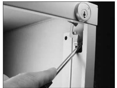
Figure 10
8. The lock is now completely installed. The file cabinet is locked with the cam and gang bar raised to the up position. (Figs. 11 & 12)
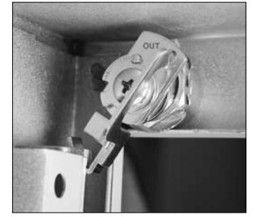
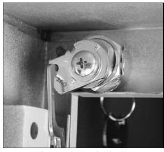
Figure 11 (locked) Figure 12 (unlocked)

18424 Highway 99 • Lynnwood, WA 98037 • 800-525-0954 206-362-3290 • Fax 206-362-3569 • www.olympus-lock.com