Olympus Lock 721 Reversing Instructions
Open the original PDF document
View PDFReversing Instructions for the 721 I.C. Core Cabinet Lock
Converting from Door to Drawer
Converting from Drawer to Door
flat surface.
STEP 1 - Remove the cylinder housing set
body. Set the lock assembly face down on a
STEP 2 - Remove the two screws and the
back cover plate from the back of the lock
body. Remove the bolt, cam disk, and prong
screw and cylinder housing from the lock
- STEP 1 Remove the cylinder housing set screw and cylinder housing from the lock body. Set the lock assembly face down on a flat surface.
- STEP 2 Remove the two screws and the back cover plate from the back of the lock body. Remove the bolt, cam disk, and prong driver from the lock body.
driver from the lock body. STEP 3 - Reinsert the cylinder housing in
door orientation and fix in place with set screw.
STEP 3 - Reinsert the cylinder housing in drawer orientation and fix in place with set screw.
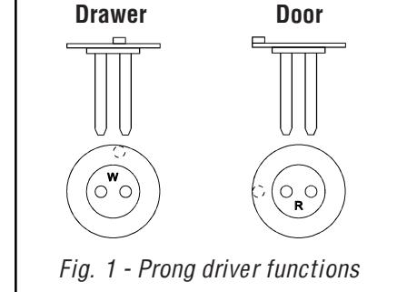
STEP 4 - Place the lock face side down on a flat surface. Install the drawer (W) prong driver first, then place the cam disk over the top in the orientation indicated in Fig. 2a.
Drawer prong

Fig. 2a - Installation of drawer prong driver and cam disk.
STEP 5 - Install the bolt so that the "CAB" side is facing you. The bolt throw should be beyond the bottom of the lock as indicated in Fig. 3a.
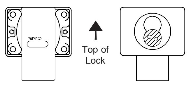
Fig. 3a - Back of drawer lock with bolt installed.
Fig. 4a - Front of drawer lock with prong driver in correct orientation.
STEP 6 - Reinstall back cover plate.
STEP 7 - Insert the black plastic actuator and turn until the bolt is completely extended and the prongs are just past horizontal as in Fig 4a.
STEP 4 - Place the lock face side down on a flat surface. Install the door (R) prong driver first, then place the cam disk over the top in the orientation indicated in Fig. 2b.

Fig. 2b - Installation of door prong driver and cam disk.
STEP 5 - Install the bolt so that the "DRWR" side is facing you. The bolt throw should be beyond the bottom of the lock as indicated in Fig. 3b.
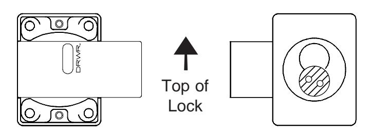
Fig. 3b - Back of door lock with bolt installed.
Fig. 4b - Front of door lock with prong driver in correct orientation.
STEP 6 - Reinstall back cover plate.
STEP 7 - Insert the black plastic actuator and turn until the bolt is completely extended and the prongs are just past horizontal as in Fig 4b.

Olympus Lock Inc. 18424 Highway 99 Lynnwood, WA 98037 www.olympus-lock.com
Phone: 206-362-3290 Toll-free: 800-525-0954 Fax: 206-362-3569