OLD MLRK1-AR
Open the original PDF document
View PDF


ARLP-UL-M-KIT
INSERT INSTRUCTIONS
The Command Access ARLP-UL-M-KIT Field Installable Motorized Latch Pullback Kit for the Adams Rite 82/84/86/88 series
KIT INCLUDES | TOOLS REQUIRED
• Phillips Screwdriver
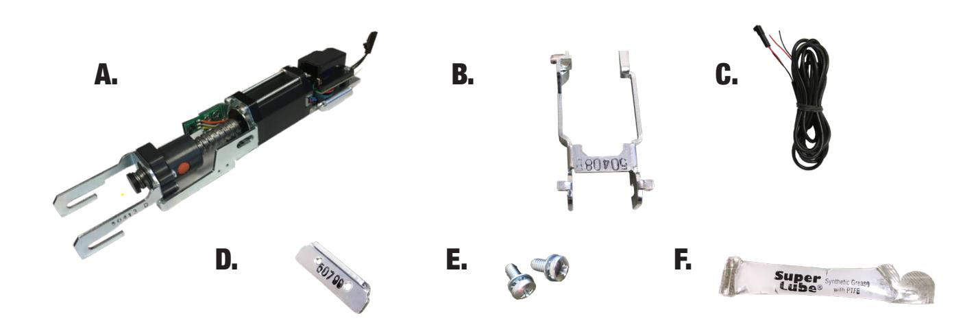
- 1 ARLP-UL-M-KIT A.
- 1 50408 Magnet Bracket B.
- 1 50436 8ft Wire Harness C.
- 1 50799 Attaching Bracket D.
- 2 40711 Phillips Head Screws E.
- 1 40393 Super Lube Package F


Technical Information
SPECIFICATIONS
- • Input Voltage: 24VDC +/- 10%
- • Wire gauge: Minimum 18 gauge
- • Direct wire run no relays or access control units in-between power supply & module
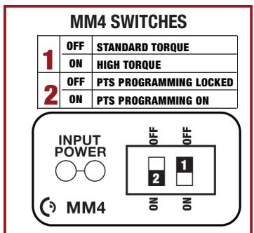
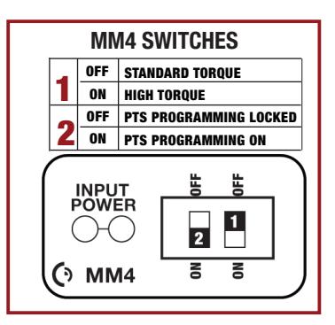
Standard Torque Mode
Average Latch Retraction Current: 1.3 A Average Holding Current: 215 mA
High Torque Mode
Average Latch Retraction Current: 2 Amp Average Holding Current: 250 mA
Setting PTS **Important Info** Make sure to set PTS before finishing installation
- Step 1 Select your preferred torque mode (ships in standard torque) Press the device push pad to the desired setting. (Recommend to fully depress and release 5%, giving the device room for changing door conditions.)
- Step 2 While depressing the push pad, apply power. (i.e. presenting the credential to the reader).
- Step 3 Continue to keep pad depressed, the device will beep 6 times. After the beeps have stopped, release the pad and now the adjustment is complete. If not to your liking repeat the 3 steps.
Troubleshooting & Diagnostics
| Beeps | Explanation | Solution |
|---|---|---|
| 2 Beeps | Over Voltage | > 30V unit will shut down. Check voltage & adjust to 24 V. |
| 3 Beeps | Under Voltage | < 20V unit will shut down. Check voltage & adjust to 24 V. |
| 4 Beeps | Failed Sensor |
Verify all 3 sensor wires are installed correctly. Replace sensor if
problem persists by contacting office. |
| 5 Beeps | Retraction or dogging failure |
After 1st fail: 5 beeps then immediately attempts to retract again.
After 2nd fail: 5 beeps with pause in-between for 30 seconds then device attempts to retract again. After 3rd fail: 5 beeps every 7 minutes, device will not attempt to retract. To Reset: Depress bar for 5 seconds at any time. |
| 6 Beeps | PUSH TO SET |
Device is recording it's new position and power mode after the
6th beep. |
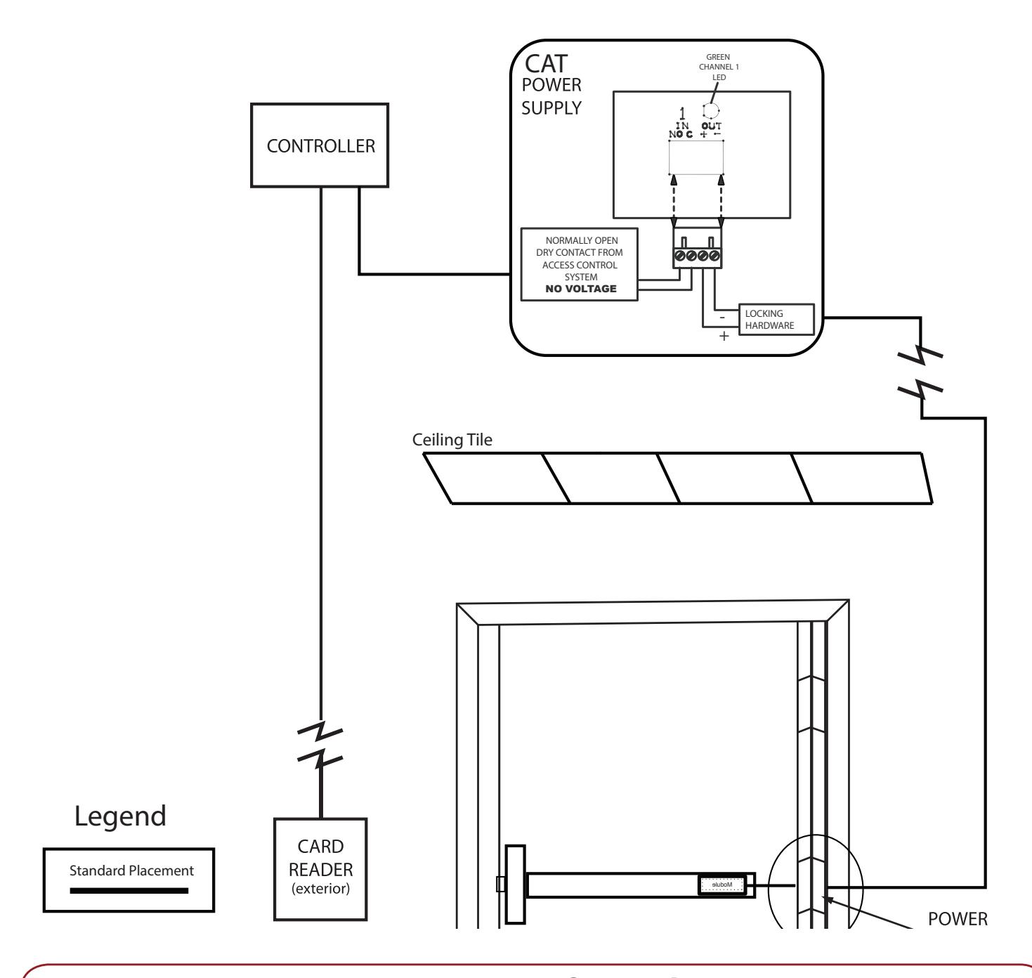
Electrified Exit Device

Installation Example
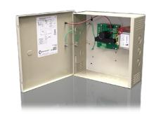
Recommended Power Supplies:
All Command Access exit devices & field installable kits have been thoroughly cycle tested with Command Access power supplies at our factory. For more information, visit our website

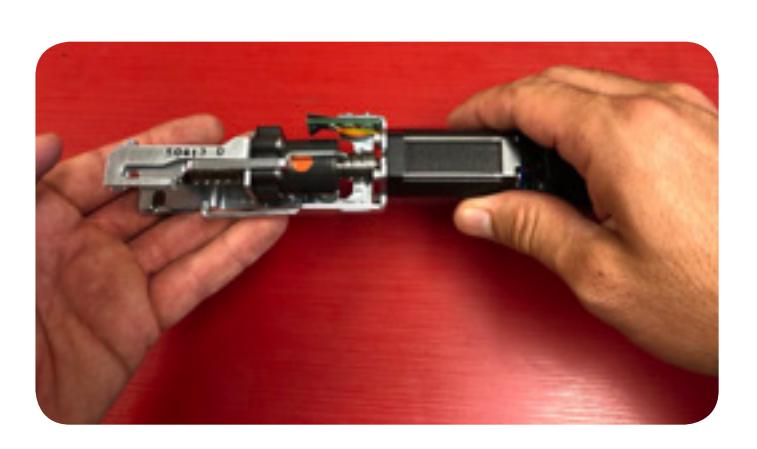
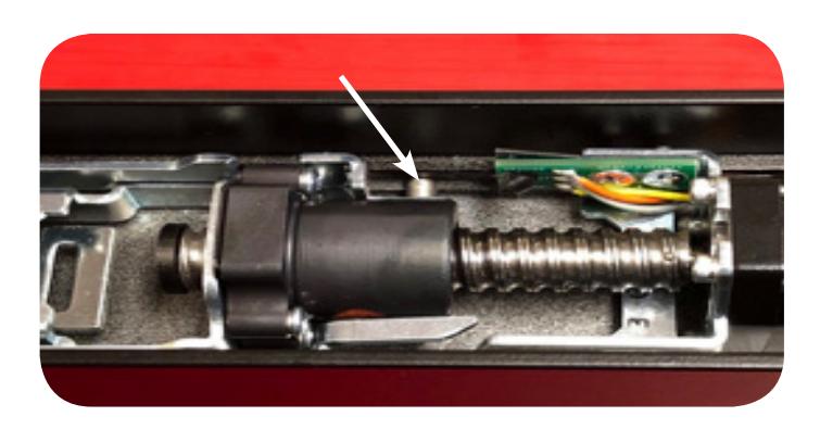
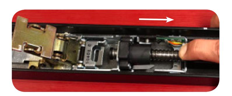
1. If Magnet Bracket comes loose during shipping, rotate ballscrew a quarter turn as pictured.
2. The ears on the magnet bracket slide on top of attaching hooks
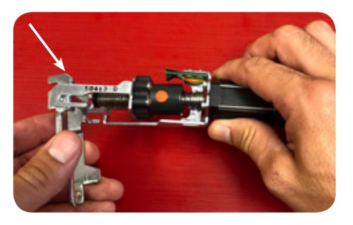
3. Left up the back of the magnet bracket to bring parallel with attaching hooks
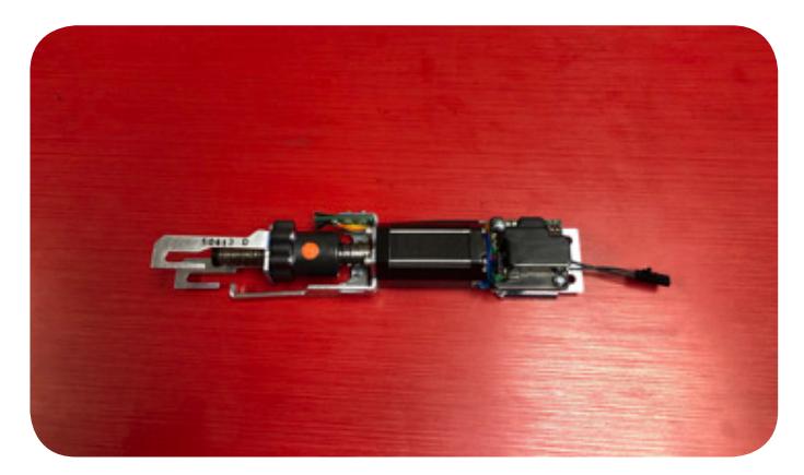
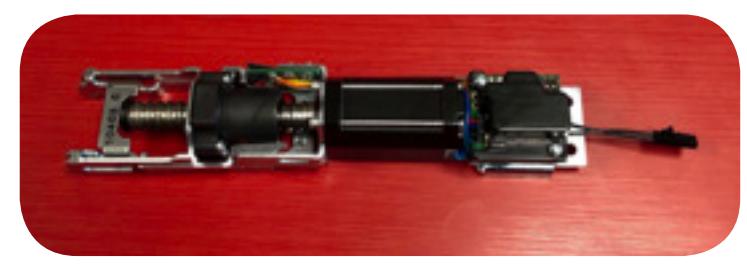
Most likely, this is how your unit will come out of the box with the magnet bracket installed.
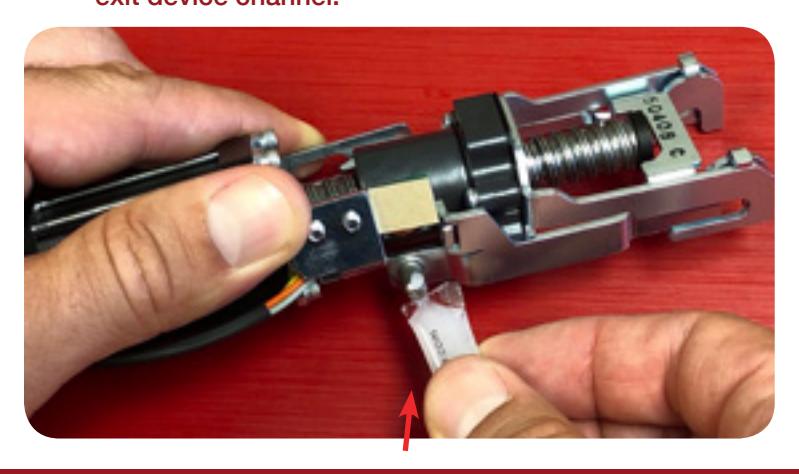
5. Apply Super Lube to top & bottom of post on magnet bracket that will be moving inside of the exit device channel.

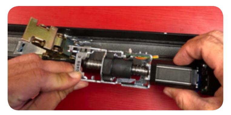
Install the motor assembly & magnet bracket into the back of the exit device behind the back activating bracket. Make sure that the lubed post slides into the middle channel.
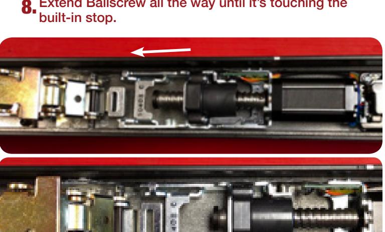
8 Extend Ballscrew all the way until it's touching the
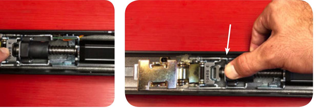
10. Place the hooks over the roll pin and slide ONLY the magnet bracket back
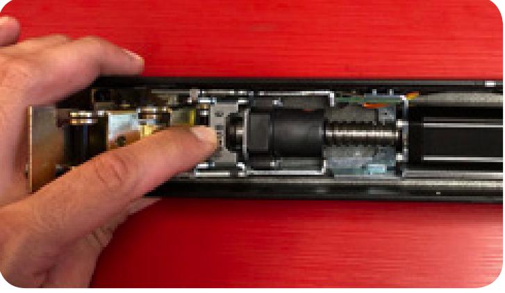
Visually confirm post is in the correct channel & that the motor assembly is siting flush on the bottom of the exit device housing
Now, we're going to hook onto the roll pin on 9 the back activating bracket.
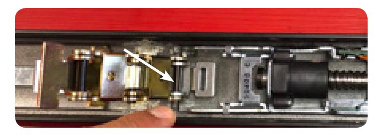
11 Next, push down on attaching hooks so they drop down over the roll pin

12. Pull back on the whole assembly to lock-in the attaching hooks.
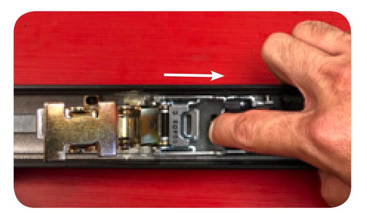
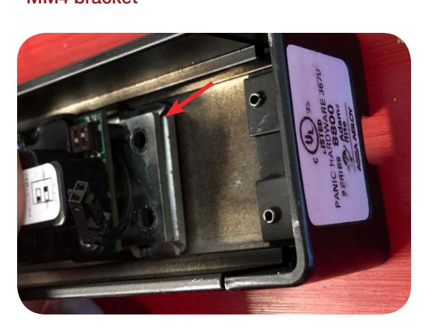
Slide forward until the tab on the attaching bracket bottoms out on the underside of the MM4 bracket
16. To find the correct position, pullback on the motor assembly until the it puts a slight tension on the back activating bracket
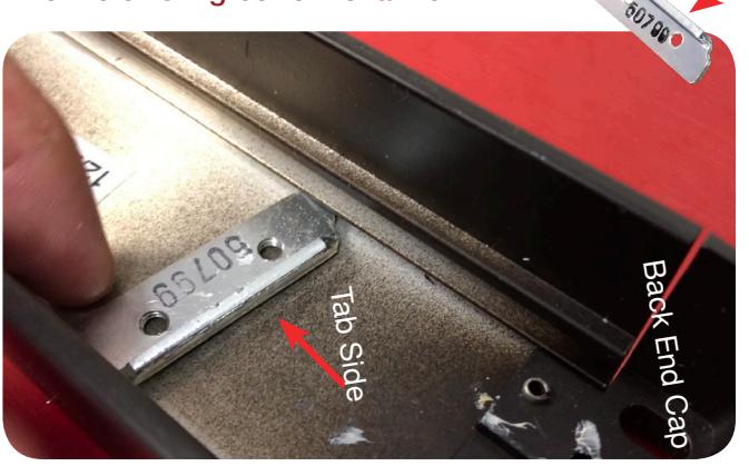
13. Grab the back-attaching bracket #50799, with the tab facing the back of the device, and slide into the existing bottom channel.
15. Drop in both screws into the back of the MM4 bracket but do not tighten yet!
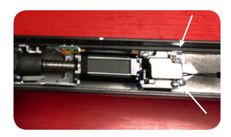
17. Tighten both screws while holding motor in correct position.
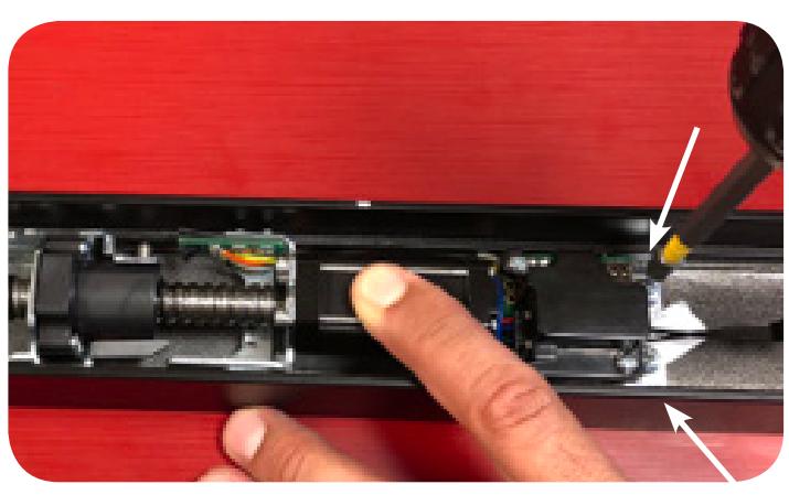

Next, hook up to power and utilize our push pad guide (or complete push pad) set the Push-to-Set adjustment. Follow steps, below 18.
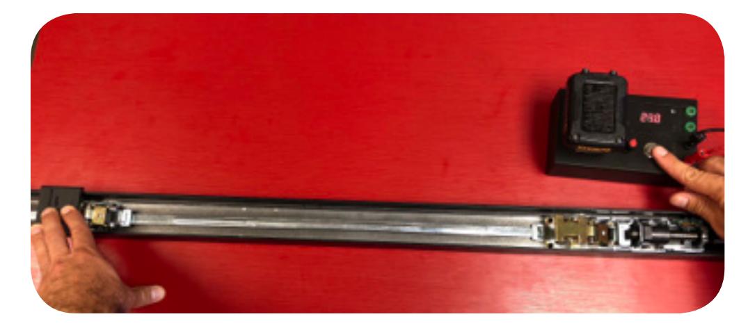
Setting PTS
- Step 1- Select your preferred torque mode (ships in standard torque) Press the device push pad to the desired setting. (Recommend to fully depress and release 5%, giving the device room for changing door conditions.)
- Step 2- While depressing the push pad, apply power. (i.e. presenting the credential to the reader).
- Step 3- Continue to keep pad depressed, the device will beep 6 times. After the beeps have stopped, release the pad and now the adjustment is complete. If not to your liking repeat the three steps.
- Step 4- Once you found the correct location, flip the dip switches to off to lock programming.