Norton Rixson Unitrol 7500 Series Door Closer (Parallel) Arm, UNI7500, UNI7700, Non-Hold Open or Hold Open Insta…_80-9377-1351-020
Open the original PDF document
View PDFUNI-7500 (DA) (H) Series Unitrol® Door Closer
Non Hold Open or Hold Open, Parallel Arm Installation Instructions


WARNING
This product can expose you to lead which is known to the state of California to cause cancer and birth defects or other reproductive harm. For more information go to www.P65warnings.ca.gov.
An incorrectly installed or improperly adjusted door closer can cause property damage or personal injury These instructions should be followed to avoid the possibility of misapplication or misadiustment.
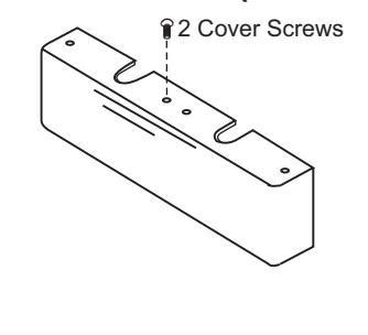
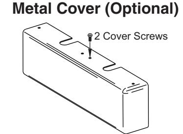
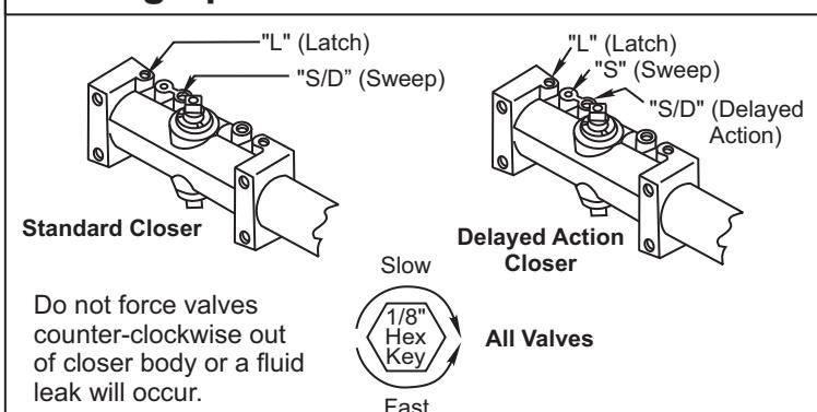
Components
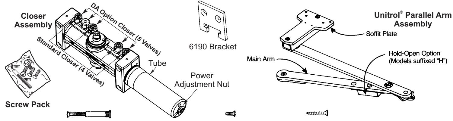
14-20 Sex Nut and Bolt -4 each, to mount closer or drop plate to door-
14-20 Machine Screw #14 Type "A" Screw -6 each, to mount soffit plate and 6190 bracket-
Optional
Cover Options
Plastic Cover (Standard)
- Use these instructions for installing all models of these series on 1-3/4" (45mm) doors hung on 4-1/2" (114mm) wide hinges or 3/4" (19mm) offset pivots.
- DOOR WIDTH determines the location of the closer. Use ONLY the template chart corresponding to your door width.
- Use ONLY the dimensions given in each template chart for the door total OPENING angle or the HOLD-OPEN angle desired.
- Unitrol<sup>®</sup> parallel arms are supplied in one of three lengths, according to door width specified on order. To verify that the ARM you have is CORRECT FOR THE DOOR WIDTH, check the number stamped on the arm against the chart.
|
DOOR
WIDTH |
Non-Holder Arm | Hold-Open Arm |
|---|---|---|
|
28"-32"
0.70-0.80M |
6100-11 | 6100-1 |
|
33"-41"
0.85-1.00M |
6100-13 | 6100-3 |
|
42"-48"
1.05-1.20M |
6100-14 | 6100-4 |

| DIMENSIONS FOR DOORS 28" TO 32" WIDE | |||||
|---|---|---|---|---|---|
| Opening | Dimension | Dimension | Dimension | ||
| Hold-Open | Stop | A | В | C | |
| 85° | 90° | 10-1/4 | 10-1/2 | 4-1/2 | |
| 90° | 95° | 9-5/8 | 9-7/8 | 3-7/8 | |
| 95° | 100° | 9-1/8 | 9-3/8 | 3-3/8 | |
| 100° | 105° | 8-3/4 | 9 | 3 | |
| 105° | 110° | 8-3/8 | 8-5/8 | 2-5/8 | |
| 110° | 115° | 8 | 8-1/4 | 2-1/4 | |
| DIMENSIONS FOR DOORS 33" TO 41" WIDE | |||||
|---|---|---|---|---|---|
| Opening | Dimension | Dimension | Dimension | ||
| Hold-Open | Stop | A | B | C | |
| 85° | 90° | 12-3/4 | 12-7/8 | 7 | |
| 90° | 95° | 12 | 12-1/8 | 6-1/4 | |
| 95° | 100° | 11-1/2 | 11-5/8 | 5-3/4 | |
| 100° | 105° | 10-7/8 | 11 | 5-1/8 | |
| 105° | 110° | 10-1/2 | 10-5/8 | 4-3/4 | |
| 110° | 115° | 10 | 10-1/8 | 4-1/4 | |
| DIMENSIONS FOR DOORS 42" TO 48" WIDE | ||||||
| Opening | Dimension | Dimension | Dimension | |||
| Hold-Open | Stop | A | В | C | ||
| 85° | 90° | 14-7/8 | 15-1/8 | 9-1/8 | ||
| 90° | 95° | 14 | 14-1/4 | 8-1/4 | ||
| 95° | 100° | 13-3/8 | 13-5/8 | 7-5/8 | ||
| 100° | 105° | 12-3/4 | 13 | 7 | ||
| 105° | 110° | 12-1/4 | 12-1/2 | 6-1/2 | ||
| 110° | 115° | 11-7/8 | 12-1/8 | 6-1/8 | ||
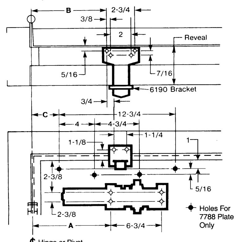
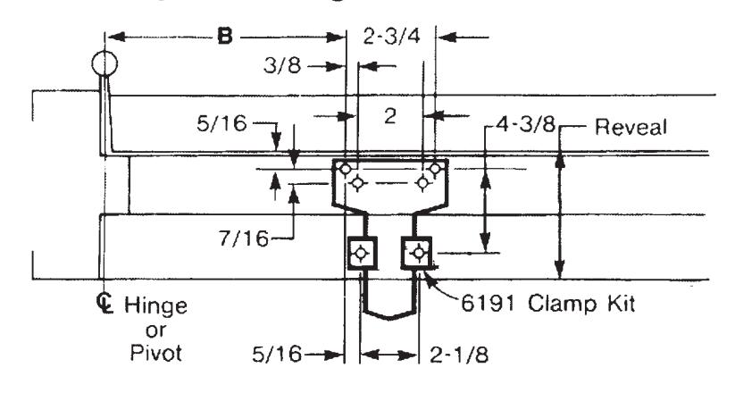
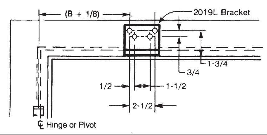
- Door template is typical for all installations.
- Frame template must be selected according to reveal.
| inches | mm | inches | mm | inches | mm | inches | mm |
| 5/16 | 8.0 | 2-3/4 | 69.9 | 8-3/8 | 213 | 11-7/8 | 302 |
| 3/8 | 9.5 | 3 | 76 | 8-5/8 | 219 | 12 | 305 |
| 7/16 | 11.1 | 3-3/8 | 86 | 8-3/4 | 222 | 12-1/8 | 308 |
| 1/2 | 12.7 | 3-7/8 | 98.5 | 9 | 229 | 12-1/4 | 311 |
| 3/4 | 19.1 | 4 | 101.6 | 9-1/8 | 232 | 12-1/2 | 318 |
| 1 | 25 | 4-1/4 | 108 | 9-3/8 | 238 | 12-3/4 | 323.9 |
| 1-1/8 | 29 | 4-3/8 | 111 | 9-5/8 | 244 | 12-7/8 | 327 |
| 1-1/4 | 31.8 | 4-1/2 | 114 | 9-7/8 | 251 | 13 | 330 |
| 1-1/2 | 38.1 | 4-3/4 | 120.7 | 10 | 254 | 13-3/8 | 340 |
| 1-3/4 | 44 | 5-1/8 | 130 | 10-1/8 | 257 | 13-5/8 | 346 |
| 1-7/8 | 48 | 5-3/4 | 146 | 10-1/4 | 260 | 14 | 356 |
| 2 | 50.8 | 6-1/4 | 159 | 10-1/2 | 267 | 14-1/4 | 362 |
| 2-1/8 | 54 | 6-3/4 | 171.5 | 10-5/8 | 270 | 14-7/8 | 378 |
| 2-1/4 | 57 | 7 | 177.8 | 10-7/8 | 276 | 15-1/8 | 384 |
| 2-3/8 | 60.5 | 8 | 203 | 11-1/2 | 292 | ||
| 2-5/8 | 67 | 8-1/4 | 210 | 11-5/8 | 295 |

Frame Template for Reveals Over 4-5/8 Door Template on Page 2
Frame Template for Flush Partitions Door Template on Page 2
Installation Sequence
• Read Front Page.
Installation ground rules and components identification are on this page.
Match hardware to opening.
Follow "Template Information" on Page 2.
· Mark mounting holes location.
Use dimensions for hold-open or door stop angle desired. Mark position of 4 holes on door for closer (or drop plate) and 6 holes on frame for soffit plate (or 4 for 2019L angle bracket).
· Prepare holes for fasteners.
See chart below.
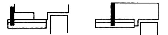
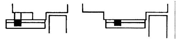
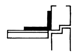
· Mount closer to door.
Drop plate first, if used. Place spring tube end toward the hinge edge of the door; closer with valves up for right hand door, with valves down for left hand door.
Mount arm to frame.
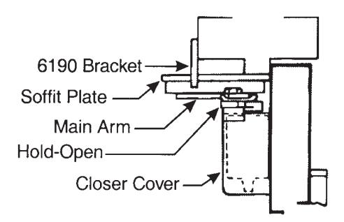
Fasten soffit plate (or angle bracket if flush partition) to frame. Mount 6190 bracket or 6191 clamps to hold soffit plate flat.
• Install arm on pinion top.
Close valve "S". Rotate pinion over 45° to align main arm letter "R" (right hand) or "L" (left hand) with pinion flat. Fasten with arm screw. See "Typical Installation" figure below.
· Adjust closer.
See "Unit Adjustment" on page 4.
Install cover.
See front page.
| Fastener | Frame | Door | Drill | ||
|---|---|---|---|---|---|
| 1/4-20 machine screw | metal | none #7 (.201 dia.) or 5.10mm. drill1/4 | |||
| #14 type "A" sheet metal screw | wood | none 3/16" (4.30mm.) | |||
| SNB | none | hollow-metal 9/32" (7.00mm.) thru 3/8" (9.50mm.) door face opposite to close | |||
| aluminum or wood | #7 (.201 dia.) or 5.10mm. drill1/4-20 tap | ||||
Pinion Flat
Typical Installation Left Hand Door Right Hand Door Valves Down Valves Up
Arm Mark
Pinion Flat
The ASSA ABLOY Group is the global leader in access solutions. Every day we help people feel safe, secure and experience a more open world.

Adjustments
Closing Speed Controls
- · Valve "S" Controls Sweep Range.
- · Valve "L" Controls Latch Range.
- Valve "D" Controls Optional Delay Range.
Closing Power Control
"Spring Power Adjustment Nut"
For 7500 Series Only
Set closer to desired size. For recommended sizes, refer to the Power Adjustment Chart below.
Install closer per instructions with proper pre-load applied to arm then adjust spring power. Power adjustment will not work properly if closer spring is not pre-loaded. To increase power, use 11/16" wrench to turn power adjustment nut clockwise. To decrease power, turn nut counter clockwise.
DO NOT use a power drill or driver to turn adjustment nut. This will damage closer and void warranty.
Closing Speed Controls
Power Adjustment Chart for Multi Size Closers
| Door Size | UNI-7500 | ||
|---|---|---|---|
| Turns from Zero | |||
| inches (m) | Interior Door | Exterior Door | |
| 28-32 (0.70-0.80) | 1 | 3 | |
| 33-41 (0.85-1.00) | 6 | 8 | |
| 42-48 (1.05-1.20) | 9 | 12 | |
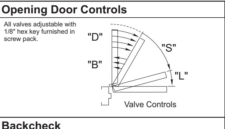
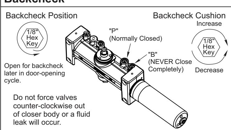
Opening Door Control
- Backcheck ("B") valve controls the hydraulic resistance to door opening. NEVER close this valve completely – it is not to provide a positive stop.
- Backcheck position ("P") valve controls the door angle where backcheck cushioning starts. Valve normally closed.
Hold Open controls are at arm elbow (models suffixed "H"). To select hold open on or hold open off and to adjust the hold open force, use screwdriver as illustrated below.

Technical Product Support: Monroe, NC 28112 USA Phone: 877.974.2255 ext: 2
Techsupport.NortonRixson@assaabloy.com
NortonRixson.com