Norton Rixson Smok-Chek V Series Closer, Model 0101, Push Side Mounting, Independent Closing Means Installation …_ISFM0101
Open the original PDF document
View PDF

SMOK-CHEK® V
A Fire/Life Safety Holder Product
Model 0101
Push Side Mounting Independent Closing Means
*85° thru Maximum Degree of Swing Single Point Hold Open
Not for Use on Doors that will be Manually Closed on a Daily Basis
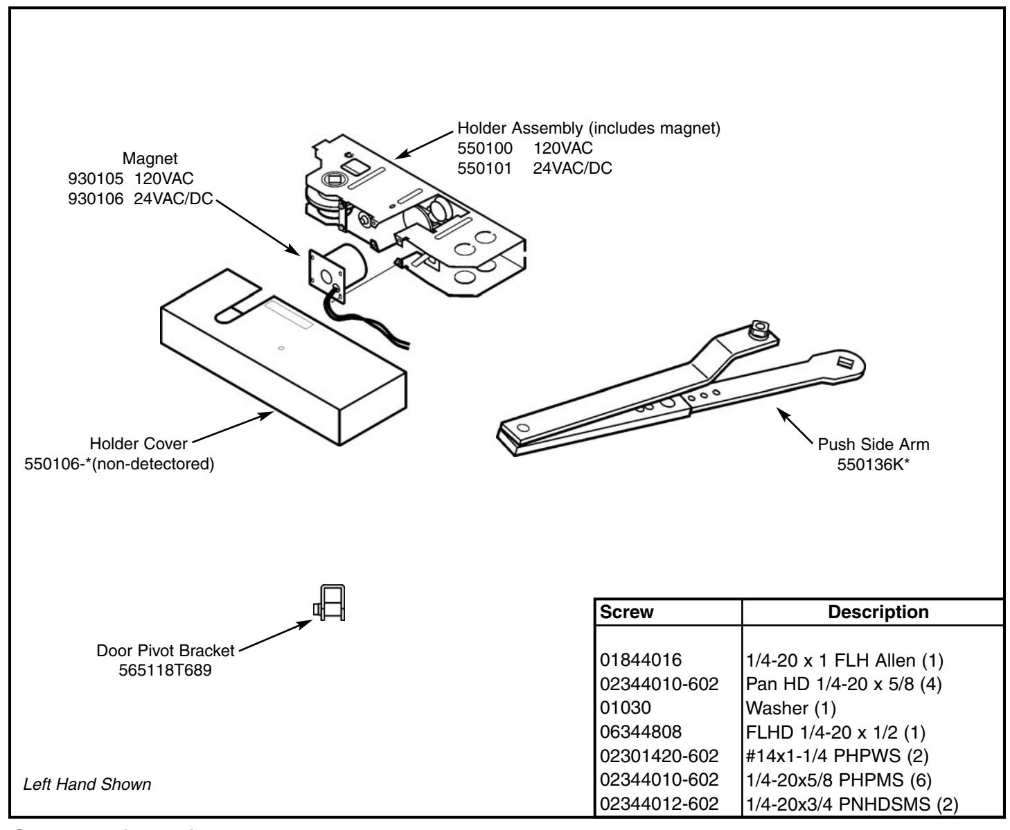
General Information:
Non Handed
Door Hanging Means:
- Standard 4", 4-1/2", or 5" Butt Hinges
- 3/4" Offset Pivot
- For other means, contact factory
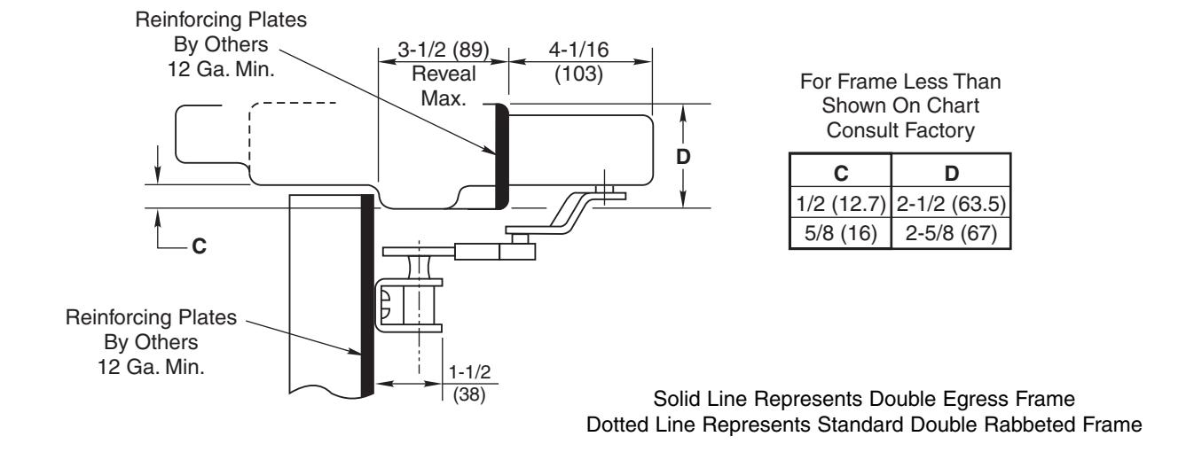
2" Minimum head frame
For frame face sizes less than 2", contact factory
Maximum reveal 3-1/2"
For reveals from 3-1/2 to 7", use arm 550789
*For hold-open from 105° - 180°, use arm 550789
Door Closing Device by others
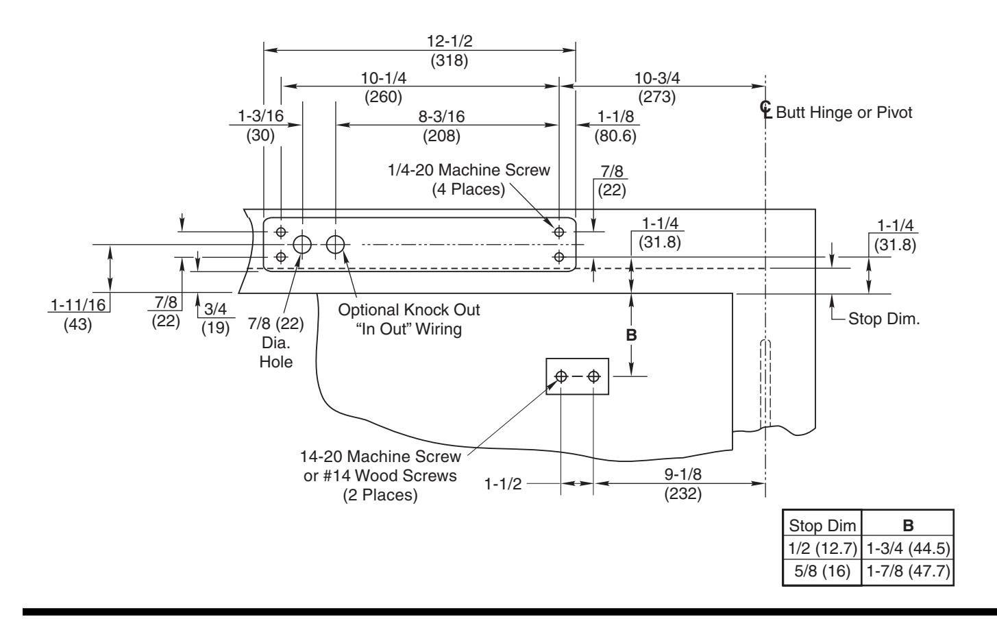
Mounting Hole Locations
- Right hand shown
- Door hanging means: 4", 4-1/2", 5" Butts or 3/4" Offset Pivots
- All dimensions given in inches (mm)
Page 2 Push Side Mounting
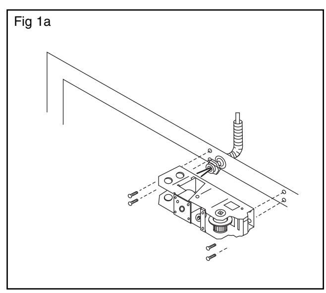
1. Mounting Holder
- A. Layout & prepare screw holes.
- B. Remove appropriate knock out in Smok-Chek & attach 3/8" (9.5) conduit fitting. (Fig. 1a)
- C. Push conduit back into frame.
- D. Attach holder with (6) 1/4-20 x 5/8 pan HD screws tighten securely.
- E. Attach arm to holder with (1) 1/4-20 x 1 FHD allen screw. (Fig. 1b)
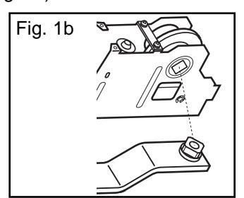
CAUTION: SQUARE ON ARM MUST BE INSERTED AND TIGHTENED INTO HOLDER VERY SECURELY BEFORE ARM IS ATTACHED TO SPINDLE OF CLOSER.
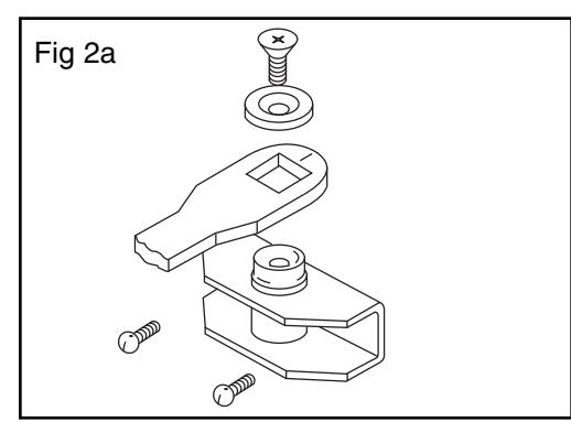
2. Mounting Door Pivot Bracket
- A. Mount door bracket to door and fasten with two 1/4-20x1/2" RDH or #14x1-1/4 Pan HD screws.
- B. Slide bracket arm into holder arm.
- C. Attach arm to bracket spindle with washer and 1/4-28x1/2" FLH screws. (Fig. 2a)
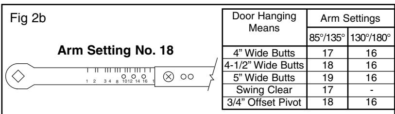
- D. Position arm as per suggested arm settings listed in chart. (Fig. 2b)
- E. Assemble holder and bracket arms together with the 1/4-20x5/16" RDH screws.
BEFORE BEGINNING WIRING, INSTALLER MUST BE GROUNDED!
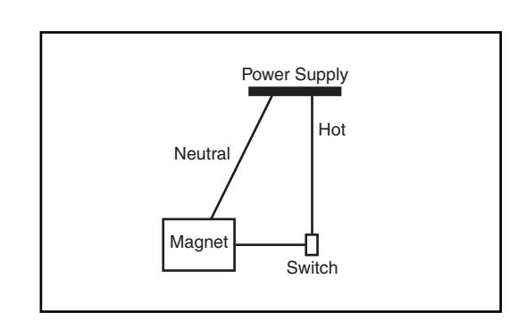
3. Electrical Wiring
Field Wires should be 18ga OR as required by local code
A. Connect switch – in series – with HOT lead of electromagnet.
Note:
120vAC draws .018 amp 24vAC/DC draws .091 amp
Page 3 Push Side Mounting
4. Making Adjustments to the Holder
- A. Closer spring force should be as low as possible. (Closer should arrive at lowest setting).
- B. Turn OFF Power (using ON/OFF switch).
-
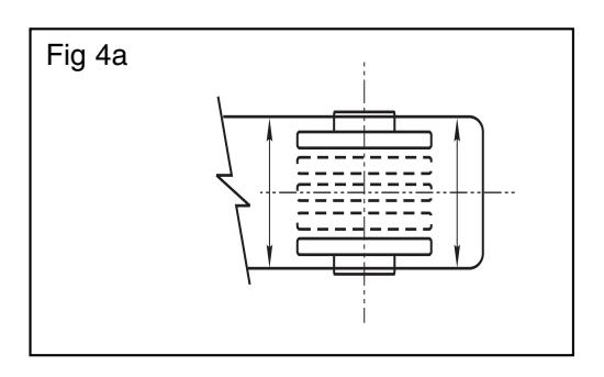
C. To set Hold Open:
- 1. Door should be in CLOSED position.
- 2. Raise or lower cam until the word "Push" is displayed from the UNDERSIDE of the unit (Fig 4a).
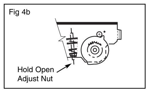
- 3. Open door to desired Hold Open position.
- 4. Raise or lower cam and ROTATE until pocket of cam is in position next to Roller A shown in Fig 4b
- 5. Release cam to re-engage teeth.
- 6. Turn ON power (using ON/OFF switch).
- 7. OPEN DOOR. Door should stay in Hold Open position–if not, repeat Steps 3 and 4.
- 8. Pull door OUT of Hold Open–door should close freely.
- 9. OPEN DOOR . If releasing force needs to be increased, turn adjusting nut IN. If lesser holding force is desired, turn nut OUT .
- 10. Attach holder cover.
Trouble-Shooting Tips:
- 1. Turn ON power.
- 2. Can door swing far enough to engage hold open? Minimum opening is 85°.
- 3. Make sure closer is at lowest spring setting.
- 4. Put piece of metal against the magnet to make sure it is receiving current.
- 5. If not, double check wiring instructions.
- 6. If so, with door in closed position look up at holder mechanism. Word PUSH should be visible, if not, adjust cam.
- 7. Turn adjusting nut.
- 8. Check arm indexing.

Copyright © 2003, 2009, 2024, ASSA ABLOY Accessories and Door Controls Group, Inc. All rights reserved. Reproduction in whole or in part without the express written permission of ASSA ABLOY Accessories and Door Controls Group, Inc. is prohibited.