Norton Rixson Slide Track Door Closers 7500ST, PS7500ST, 7700ST, PS7700ST Push or Pull, Non-Hold Open or Hold Open…_80-9377-0510-020
Open the original PDF document
View PDF7500ST Slide Track Door Closer
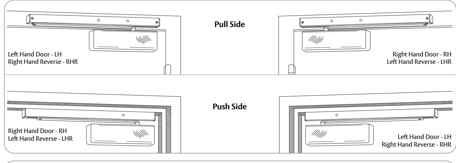
Pull Side Push Side
With or without DA suffix (delayed action) With or without M suffix (metal cover)
Non Hold Open Arm Models 7500ST PS7500ST
Hold Open Arm Models* 7500ST-H PS7500ST-H
*not permitted on fire door assemblies

ASSA ABLOY

This product can expose you to lead which is known to the state of California to cause cancer and birth defects or other reproductive harm. For more information go to www.P65warnings.ca.gov.
Ce produit peut vous exposer au plomb qui, dans l'état de la Californie, est reconnu pour causer le cancer, des anomalies congénitales ou d'autres problèmes de reproduction. Pour plus d'informations, visitez: www.P65warnings.ca.gov.


ATTENTION:
An incorrectly installed or improperly adjusted door closer can cause property damage or personal injury. These installation instructions should be followed to avoid the possibility of misapplication or misadjustment.
- For special applications, a separate door and frame preparation template is packed with these instructions. Use these instructions for installation sequence and closer adjustments only.
- 7500 Series closing force is adjustable from 1-6 as outlined in ANSI Standard A156.4. When closer is adjusted to conform to ADA reduced opening force requirements (5 lbs max.) for interior doors, it may not have adequate closing force to reliably close and latch door. Charted power adjustments in instructions are recommended where possible, to ensure proper door control.
- Adjust closing time speed between 3 7 seconds from 90° 0°.
- These door closers should NOT be installed on exposed side (weather side) of exterior doors.
- Minimum top rail of door with frame stop for PULL Side mount is 3-1/2" (89mm) without drop plate; 2-5/8" (67) with 7786JP drop plate. Minimum top rail of door with frame stop for PUSH Side mount is 6" (152mm) without drop plate; 2-5/8" (67) with 7786JP drop plate.
- Doors should be hung on ball bearing or anti-friction hinges.
- A separate door stop is recommended.
- Always consult door/frame manufacturer for fastener compatibility.
- Door and frame must be properly reinforced.
- Dimensions are given in inches (millimeters).
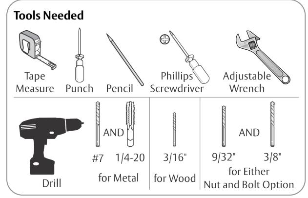
| Mounting Hardware | Door or Frame | Drill | ||
|---|---|---|---|---|
|
Track:
1/4-14 x 1-1/2 Flat Head Self Drilling Screw |
Wood | 3/16" (4.76mm) | ||
| Aluminum or Metal | no drill required | |||
|
Closer:
1/4-14 x 3 Flat Head Self Drilling Screw |
Wood | 3/16" (4.76mm) | ||
| Aluminum or Metal | no drill required | |||
|
Track:
1/4-20 x 1-1/2 Oval Head Machine Screw |
Drill #7 (.201 dia. or 5.10mm)
Tap 1/4-20 |
|||
|
Closer:
1/4-20 x 3 Flat Head Machine Screw |
Metal | |||
|
Closer or Track:
Sleeve Nut and Bolt (SNB) (optional) |
Hollow Metal |
9/32" (7.00mm) thru
3/8" (9.50mm) door face opposite to closer |
||
| Aluminum or Wood | 3/8" (9.50mm) thru | |||
|
Closer or Track:
Thru Bolt and Grommet Nut (TBGN) (optional) |
All |
9/32" (7.00mm) thru
3/8" (9.50mm) dia. x 3/8" (9.500mm) deep, door face opposite to closer |
||
7500ST Slide Track (PULL SIDE)

ASSA ABLOY
Installation Sequence:
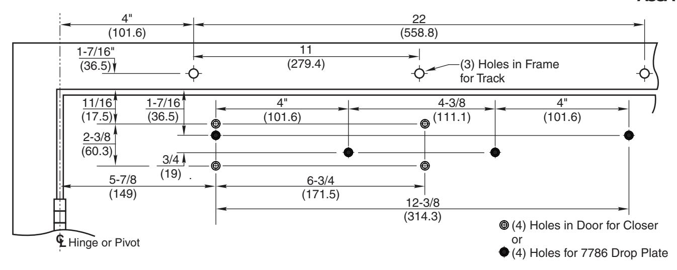
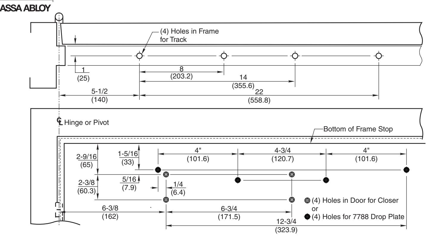
- Use template to locate holes on door and frame: four (4) on door for closer or drop plate three (3) on frame face for track assembly
- 2. Prepare door and frame for fasteners using chart on page 2.
FOR 7500 SERIES MODELS ONLY set closer power for door size using chart on page 5.
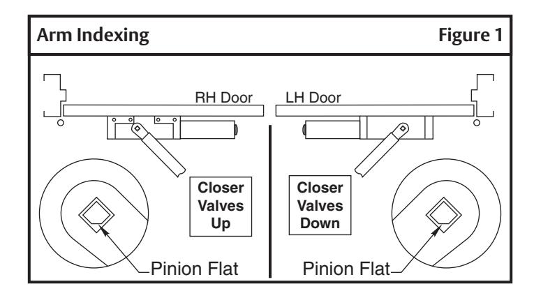
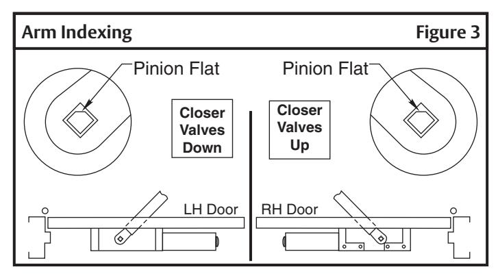
- Fasten closer body to door with power adjustment nut toward lock edge of door and with valves UP for Right Hand door valves DOWN for Left Hand door
- 4. Fasten slide track to frame face with open side facing down and spring buffer end toward hinge edge of door.
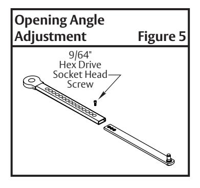
- 5. Adjust arm to shortest length and install 9/64" hex drive socket head screw from screw pack.
- 6. Place slide arm on pinion shaft using Arm Indexing instructions. (Figure 1)
- 7. Secure arm with arm washer and arm screw.
- 8. Insert arm stud into slide block in track assembly. Secure by pushing in on retainer clip that extends from slide block in track, until it is flush with slide block.
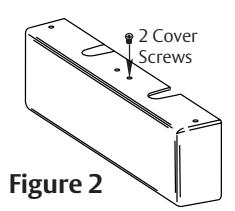
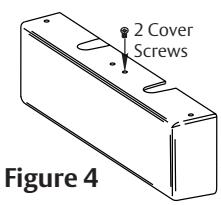
- 9. Install cover (Figure 2) or make adjustments.

IMPORTANT: From centerline of pivot point to end of track is 26-1/2" (673mm)
- Right hand door shown
- Do not scale drawing
- Dimensions are given in inches (mm)
- Min. ceiling clearance for unit is 2" (50mm) from frame rabbet 110° Max. Non Hold Open with Spring Buffer 180° Max. Non Hold Open without Spring Buffer.
180° Max. – Non Hold Open without Spring Buffer
110° Max. – Hold Open
You've now installed the 7500ST Closer - PULL side.
Go to page 5 for closer adjustments.
7500ST Slide Track (PUSH SIDE)
Installation Sequence:
- Use template to locate holes on door and frame: four (4) on door for closer or drop plate four (4) on frame soffit for track assembly
- 2. Prepare door and frame for fasteners using chart on page 2.
FOR PS7500 SERIES MODELS ONLY set closer power for door size using chart on page 5.
- Fasten closer body to door with power adjustment nut toward lock edge of door and with valves UP for Right Hand door valves DOWN for Left Hand door
- 4. Fasten slide track to frame soffit with open side facing down and spring buffer end toward hinge edge of door.
- 5. Adjust arm to shortest length and install 9/64" hex drive socket head screw from screw pack.
- 6. Place slide arm on pinion shaft using Arm Indexing instructions. (Figure 3)
- 7. Secure arm with arm washer and arm screw.
- Insert arm stud into slide block in track assembly. Secure by pushing in on retainer clip that extends from slide block in track, until it is flush with slide block.
- 9. Install cover (Figure 4) OR make adjustments.

IMPORTANT: From centerline of pivot point to end of track is 28" (711mm)
- Left hand door shown
- Do not scale drawing
- Dimensions are given in inches (mm)
- Maximum door opening:
100° Max. – Non Hold Open with Buffer in track
125° Max. – Non Hold Open without Buffer in track; auxiliary door stop required
100° Max. – Hold Open
You've now installed the 7500ST Closer - PUSH side.
Go to page 5 for closer adjustments.
The ASSA ABLOY Group is the global leader in access solutions. Every day we help people feel safe, secure and experience a more open world.

Adjustments
Door Opening Angle and/or Hold Open Angle (Figure 5)
Remove 9/64" hex drive socket head screw from arm. Open door to desired angle and install hex-drive socket head screw into hole in adjusting rod that is aligned with hole in adjusting tube.
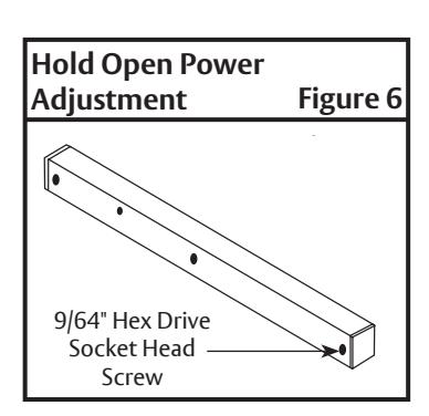
On/Off Hold Open Feature (Figure 6)
Slotted screw, accessible through hole in face of track, engages or disengages hold open feature with 1/4 turn of screw. Hold open units are not permitted in fire door assemblies.
Hold Open Power Adjustment (Figure 6)
If more hold open power is required, power may be increased by turning adjustment screw in end of the track nearest hinges. Use 9/64" hex wrench provided and rotate adjustment screw clockwise to increase holding power.
Closing Power
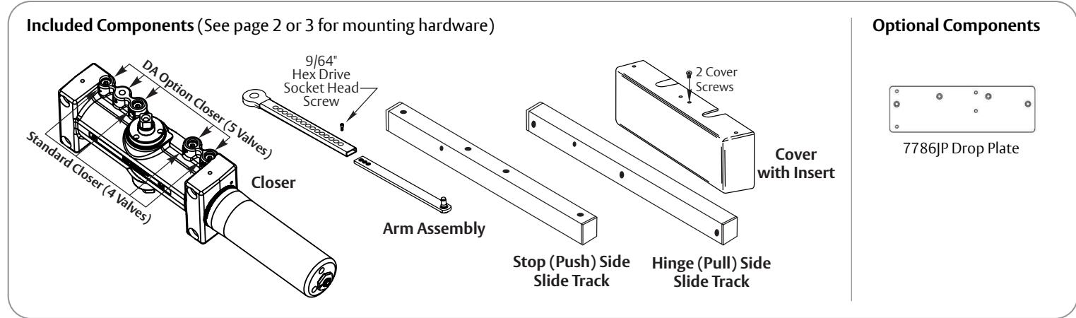
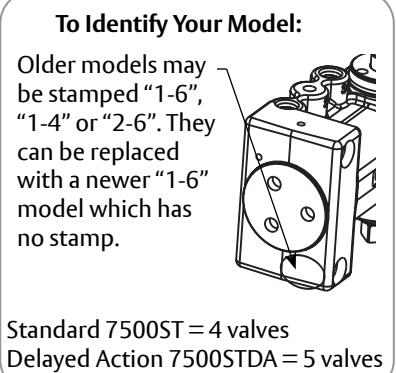
7500ST Models are fully adjustable for proper sizing. (Figure 7)
To adjust closer power, install closer per instructions with proper pre-load applied to arm then adjust spring power.
NOTE: Power adjustment will not work properly if closer spring is not pre-loaded.
Closing Cycle (hydraulic control) (Figure 8) Standard Closer Only
- Valve "L" controls door speed in Latch range.
- Valve "S/D" controls door speed in Sweep range.
Delayed Action Closer Only
- Valve "L" controls door speed in Latch range.
- Valve "S" controls door speed in Sweep range.
- Valve "S/D" controls door speed in Delay range.
Opening Cycle (hydraulic control) (Figure 8)
- Valve "B" cushions (slows) door opening in backcheck range.
- Valve "P" allows "backcheck" to begin later in opening cycle.
|
7500 Models
Closing Power Adjustment Figure |
|||||
|---|---|---|---|---|---|
|
Maximum
Interior Door Size inches / (meters) |
Maximum
Exterior Door Size inches / (meters) |
||||
| 30 / (.76) | 0 | 30 / (.76) | 2 | ||
| 36 / (.91) | 2 | 36 / (.91) | 5 | ||
| 42 / (1.07) | 5 | 42 / (1.07) | 8 | ||
| 48 / (1.22) | 8 | 48 / (1.22) | 11 | ||
NOTE: Maximum of 16-1/2 turns (360°) of Spring Power Adjustment Nut.
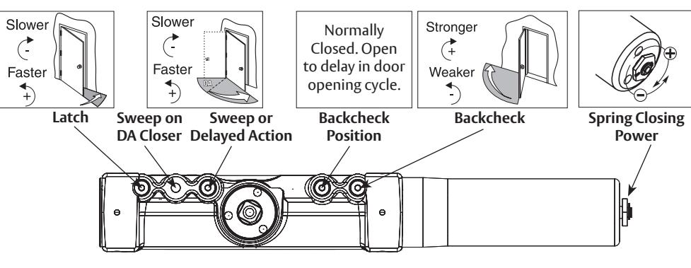
Figure 8

Use provided hex wrench to turn valves. NEVER force valves out of closer. NEVER completely close backcheck valve.
Door must be open to adjust spring closing power. Do not use a power drill. Warranty will be void.
Technical Product Support: Monroe, NC 28112 USA Phone: 877.974.2255 ext: 2 Techsupport.NortonRixson@assaabloy.com NortonRixson.com