Norton Rixson No. 55 Checkmate Series Door Stop and Holder,Surface Mounted,Non-Adjustable Template_OH80080A
Open the original PDF document
View PDF
INSTALLATION INSTRUCTIONS
- 1. Select and determine degree of hold open or dead stop from chart on back side of page.
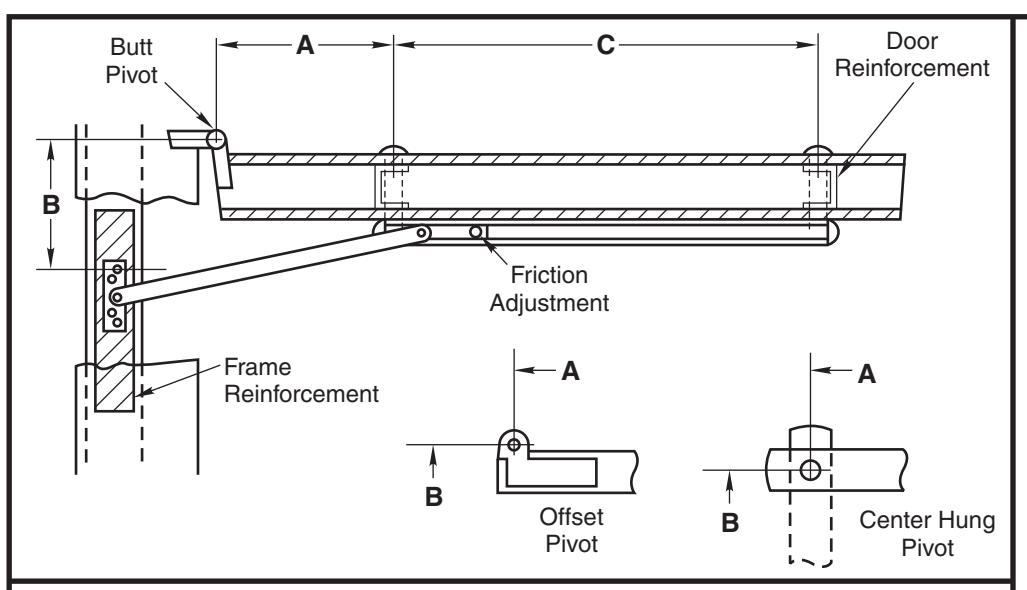
- 2. Locate "A" and "B" dimensions on door and frame.
3/16
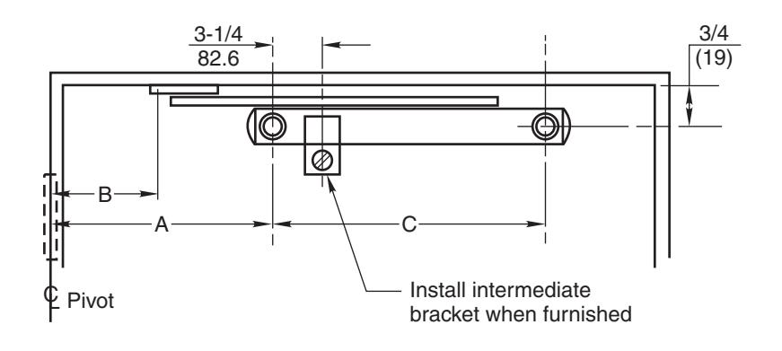
3. Install iamb (4.8)(76.2)bracket on stop 7/16 1-1/2 7/16 1/4 5/16 strip as shown. (6.4)(7.9)(11.1)(38.1)(1.1)3/4 (19)1/4 (6.4)B<del></del>← Frame 4. Position channel Reinforcement on door with shock end located towards pivot. Drill 5/16 (7.9) dia. sex bolt hole, "A" dimension, 3/4 (19) down from stop strip 3/4 as shown. Door (19)Reinforcement
5. Install channel on door with "A" dimension sex bolt. Locate "C" dimension sex bolt hole making sure that channel is horizontal and parallel with stop strip. Drill 5/16 (7.9) dia. sex bolt hole and finish installing holder.
Notes:
- All hollow metal frames should be properly reinforced with 3/16" (4.8) min. thickness x 12" (304.8) min. length reinforcement plates.
- All hollow metal doors are to have minimum 3/16" (4.8) reinforcement plates.
- All drilling and tapping to be done by field men.
- Suggest mounting door stop or holder first and then other hardware to clear. Contact factory if interference results with other hardware.
- Jamb bracket to be on same centerline as channel.
- Intermediate bracket #12 x 3/4" FSMS.
- All dimensions are given in inches (mm).
Caution:
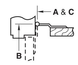
Note location of swing clear hinge centerline to determine "A" and "B" dimensions.
| Screw Details | |||||||||||
|---|---|---|---|---|---|---|---|---|---|---|---|
| Jamb | Door | ||||||||||
| #12-24 x 1/2" FHMS | #12-24 x 1-1/2" FHMS | ||||||||||
| ı | or | and | |||||||||
| ı | #12 x 1-1/2" FHWS | 5/16" Dia. Sex Bolt | |||||||||
| (4 Places) | (2 Places) | ||||||||||
No. 55 Series Surface Mounted Non Adjustable Door Stops and Holders
RIXSON ASSA ABLOY
TEMPLATE NUMBER OH80080A 1 of 2
Approved 2022-05-02
2 01/22
No. 55 Series Surface Mounted Door Stops and Holders
- 1. See other side for installation instructions.
- 2. Select proper dimensions noted below.
- 3. All drilling and tapping to be done by field man.
- 4. All dimensions given in inches (mm). Metric = decimal (numerator divided by denominator) x 25.4.
Reversible, non-handed.
H.O. = Hold Open D.S. = Dead Stop
|
Device
Number |
Degree | 85° | 90° | 95° | 100° | 105° | 110° | |||||||||||||||||||||
|---|---|---|---|---|---|---|---|---|---|---|---|---|---|---|---|---|---|---|---|---|---|---|---|---|---|---|---|---|
|
H.O.
D.S. |
H.O.
D.S. |
H.O.
D.S. |
H.O. | D.S. | H.O. | D.S. | H.O. | D.S. | ||||||||||||||||||||
| 1-3/4 - 2-1/4 | H.O. | Stop |
Door
Opening |
A | B | A | B | A | B | A | B | A | B | A | B | A | B | A | B | A | B | A | B | A | B | A | B | C |
| (44.5 - 57.2) | 55-126 | 55-136 | 18 - 24 | 2-1/4 | 4-5/8 | 2-7/8 | 4-5/8 | 1-15/16 | 4-5/16 | 2-9/16 | 4-5/16 | 1-5/8 | 4 | 2-1/4 | 4 | 1-3/8 | 3-3/4 | 2 | 3-3/4 | 1-3/16 | 3-9/16 | 1-13/16 | 3-9/16 | – | – | 1-9/16 | 3-5/16 | 13-11/16 |
|
Butts
& 3/4 (19) |
55-226 | 55-236 | 24-1/16 - 30 | 6-7/16 | 5-11/16 | 7-1/16 | 5-11/16 | 6-1/16 | 5-5/16 | 6-11/16 | 5-5/16 | 5-11/16 | 4-15/16 | 6-5/16 | 4-15/16 | 5-3/8 | 4-5/8 | 6 | 4-5/8 | 5-1/8 | 4-3/8 | 5-3/4 | 4-3/8 | 4-7/8 | 4-3/16 | 5-1/2 | 4-3/16 | 14-13/16 |
| 55-326 | 55-336 | 30-1/16 - 36 | 9-9/16 | 7-1/4 | 10-3/16 | 7-1/4 | 9-1/8 | 6-13/16 | 9-3/4 | 6-13/16 | 8-11/16 | 6-3/8 | 9-5/16 | 6-3/8 | 8-5/16 | 6 | 8-15/16 | 6 | 8 | 5-11/16 | 8-5/8 | 5-11/16 | 7-11/16 | 5-3/8 | 8-5/16 | 5-3/8 | 16-5/8 | |
| Offset Pivot | 55-426 | 55-436 | 36-1/16 - 42 | 13-3/16 | 9-3/8 | 13-13/16 | 9-3/8 | 12-5/8 | 8-13/16 | 13-1/4 | 8-13/16 | 12-1/16 | 8-1/4 | 12-11/16 | 8-1/4 | 11-5/8 | 7-13/16 | 12-1/4 | 7-13/16 | 11-1/4 | 7-7/16 | 11-7/8 | 7-7/16 | 10-7/8 | 7-1/16 | 11-1/2 | 7-1/16 | 19-1/8 |
| 55-526 | 55-536 | 42-1/16 - 48 | 17-9/16 | 11 | 18-3/16 | 11 | 16-7/8 | 10-5/16 | 17-1/2 | 10-5/16 | 16-1/4 | 9-11/16 | 16-7/8 | 9-11/16 | 15-3/4 | 9-3/16 | 16-3/8 | 9-3/16 | 15-1/4 | 8-11/16 | 15-7/8 | 8-11/16 | 14-7/8 | 8-5/16 | 15-1/2 | 8-5/16 | 20-7/8 | |
|
Device
Number |
Degree | 85° | 90° | 95° | 100° | 105° | 110° | |||||||||||||||||||||
|
H.O.
D.S. |
H.O.
D.S. |
H.O. | D.S. | H.O. | D.S. | H.O. | D.S. | H.O. | D.S. | |||||||||||||||||||
| H.O. | Stop |
Door
Opening |
A | B | A | B | A | B | A | B | A | B | A | B | A | B | A | B | A | B | A | B | A | B | A | B | C | |
| 1-3/4 - 2-1/4 | 55-126 | 55-136 | 21 - 26-1/2 | 2-3/4 | 5-1/8 | 3-3/8 | 5-1/8 | 2-7/16 4-13/16 3-1/16 4-13/16 2-3/16 4-9/16 2-13/16 4-9/16 | 1-15/16 4-5/16 2-9/16 | 4-5/16 | 1-3/4 | 4-1/8 | 2-3/8 | 4-1/8 | 1-5/8 | 4 | 2-1/4 | 4 | 13-11/16 | |||||||||
|
(44.5 - 57.2)
Center Hung |
55-226 | 55-236 | 26-9/16 - 32 | 7-1/8 | 6-3/8 | 7-3/4 | 6-3/8 | 6-11/16 | 5-15/16 | 7-5/16 | 5-15/16 | 6-3/8 | 5-5/8 | 7 | 5-5/8 | 6-1/16 5-5/16 6-11/16 5-5/16 | 5-13/16 5-1/16 6-7/16 | 5-1/16 | 5-9/16 4-13/16 6-3/16 4-13/16 | 14-13/16 | ||||||||
| 55-326 | 55-336 | 32-1/16 - 38 | 10-3/16 | 7-7/8 | 10-13/16 | 7-7/8 | 9-3/4 | 7-7/16 | 10-3/8 | 7-7/16 | 9-5-16 | 7 | 9-15/16 | 7 | 8-15/16 | 6-5/8 | 9-9/16 | 6-5/8 | 8-9/16 | 6-1/4 | 9-3/16 | 6-1/4 | 8-5/16 | 6 | 8-15/16 | 6 | 16-5/8 | |
| 55-426 | 55-436 | 38-1/16 - 45 | 13-7/8 | 10-1/16 | 14-1/2 | 10-1/16 | 13-1/4 | 9-7/16 | 13-7/8 | 9-7/16 | 12-3/4 | 8-15/16 | 13-3/8 | 8-15/16 | 12-5/16 | 8-1/2 | 12-15/16 | 8-1/2 | 11-7/8 | 8-1/16 | 12-1/2 | 8-1/16 | 11-9/16 | 7-3/4 | 12-3/16 | 7-3/4 | 19-1/8 | |
| 55-526 | 55-536 | 45-1/16 - 48 | 18-1/4 | 11-11/16 | 18-7/8 | 11-11/16 | 17-1/2 | 10-15/16 | 18-1/8 | 10-15/16 | 16-7/8 | 10-5/16 | 17-1/2 | 10-5/16 | 16-3/8 | 9-13/16 | 17 | 9-13/16 | 15-7/8 | 9-5/16 | 16-1/2 | 9-5/16 | 15-1/2 | 8-15/16 | 16-1/8 | 8-15/16 | 20-7/8 | |
No. 55 Series Surface Mounted Non Adjustable Door Stops and Holders
NORTON RIXSON
SHEET
DATE
TEMPLATE NUMBER REV 2 01/22 OH80080B 2 of 2