Norton Rixson No. 5 Checkmate Series Door Stop and Holder,Non-Adjustable,Concealed Template_OH80020A
Open the original PDF document
View PDF
INSTALLATION INSTRUCTIONS
1. Determine degree of hold open or dead stop required. Then select proper dimensions from chart on opposite side of page.
NOTE: Add 5/8" (15.8) to "A" dimension for dead stop.
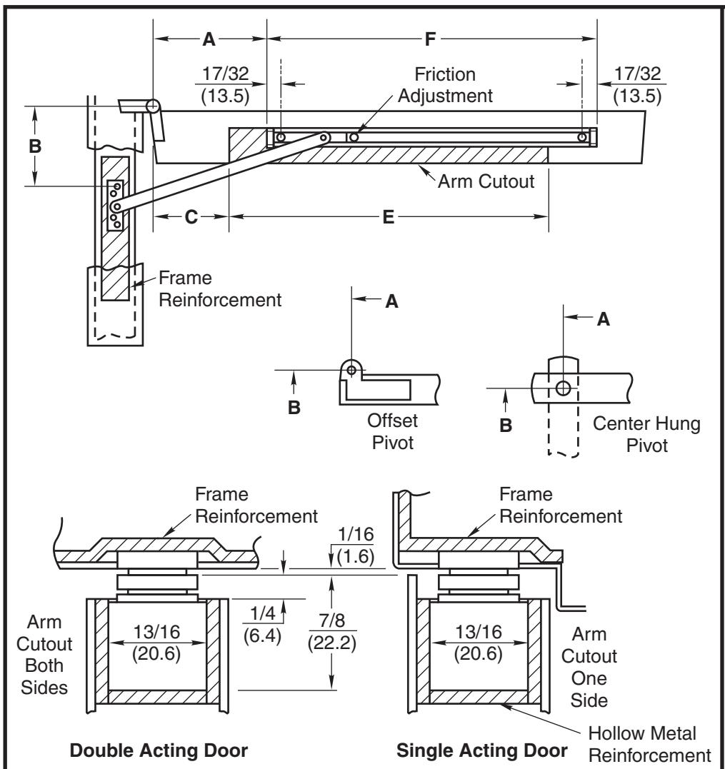
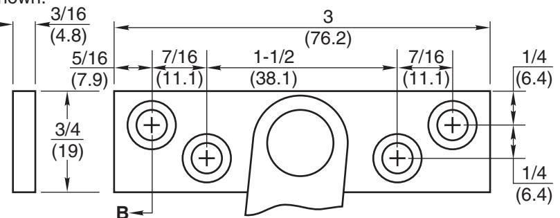
2. Locate "B" dimension on frame and mortise 3/16" (4.8) deep for jamb bracket as shown.
- 3. Locate "A" and "F" dimensions on centerline of door and mortise 13/16" wide x 7/8" deep (20.6 x 22.2) for channel, 1/16" (1.6) head clearance shown. Coordinate the arm and rail cutout dimensions if head clearance varies.
- 4. Locate "C" And "E" dimensions on top of door and mortise 1/4" (6.4) deep as shown for arm clearance.
- 5. Install door stop or holder with screws provided.
Notes:
- All hollow metal frames are to be provided with 3/16" (4.8) min. thickness x 12" (304.8) min. length reinforcement plates.
- All hollow metal doors are to have minimum 3/16" reinforcement plates.
- If dead stop is required add 5/8" (15.8) to "A" dimension as noted on opposite side of page.
- Jamb bracket to be on same centerline as channel.
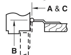
- A, B and C dimensions are measured from centerline of pivot, not edge of door.
- Reversible, non-handed.
- All dimensions are given in inches (mm).
Caution
Note location of swing clear hinge centerline to determine "A" and "B" dimensions.
| Screw Details | |||||||||
|---|---|---|---|---|---|---|---|---|---|
| Jamb | Door | ||||||||
| #12-24 x 1/2" FHMS | #12-24 x 1-1/2" FHMS | ||||||||
| or | or | ||||||||
| #12 x 1-1/2" FHWS | #12 x 1-1/2" FHWS | ||||||||
No. 5 Series Non Adjustable Concealed Door Stops and Holders
ASSA ABLOY TEMPLATE NUMBER SHEET REV DATE OH80020A 1 of 2 2 01/22
NORTON
No. 5 Series Concealed Door Stops and Holders
- 1. See other side for installation instructions.
- 2. Select proper dimensions noted below.
- 3. Add 5/8" to "A" dimension for dead stop.
- 4. All dimensions given in inches. Metric = decimal (numerator divided by denominator) x 25.4.
When Using Center Hung Pivots, Check Pivot Manufacturer's Compatibility Prior to Specifying
* Butt mounting only. Reversible, non-handed.
|
Device
Number |
Degree | 85° H.O. | 90° H.O. | 95° H.O. | 100° H.O. | 105° H.O. | 110° H.O. | |||||||||||||||||||||
|---|---|---|---|---|---|---|---|---|---|---|---|---|---|---|---|---|---|---|---|---|---|---|---|---|---|---|---|---|
| 1-3/4 - 2-1/4 | H.O. | Stop |
Door
Opening |
A | B | C | E | A | B | C | E | A | B | C | E | A | B | C | E | A | B | C | E | A | B | C | E | F |
|
(44.5 - 57.2)
Butts |
5-126 | 5-136 | *18 - 24 | 2-5/16 | 4-5/8 | 1-1/2 | 13-13/16 | 2 | 4-5/16 | 1-1/2 | 13-9/16 | 1-13/16 | 4-1/8 | 1-1/2 | 13-5/16 | 1-9/16 | 3-7/8 | 0 | 14-7/16 | 1-3/8 | 3-11/16 | 0 | 14-3/8 | 1-3/16 | 3-1/2 | 0 | 14-3/16 | 14-3/4 |
| & | 5-226 | 5-236 | 24-1/16 - 30 | 6-1/2 | 5-13/16 | 5-1/2 | 15-3/16 | 6-3/16 | 5-1/2 | 5-1/2 | 14-13/16 | 5-13/16 | 5-1/8 | 5-1/2 | 14-1/2 | 5-1/2 | 4-13/16 | 5 | 14-11/16 | 5-1/4 | 4-9/16 | 4-3/4 | 14-11/16 | 5-1/16 | 4-3/8 | 4-1/2 | 14-9/16 | 15-7/8 |
| 3/4 (19) | 5-326 | 5-336 | 30-1/16 - 36 | 9-11/16 | 7-3/8 | 7-1/2 | 18 | 9-1/4 | 6-15/16 | 7 | 18-1/16 | 8-13/16 | 6-1/2 | 6-3/4 | 17-7/8 | 8-7/16 | 6-1/8 | 6 | 18-1/4 | 8-1/8 | 5-13/16 | 6 | 18-1/16 | 7-7/8 | 5-9/16 | 5-3/4 | 17-15/16 | 17-11/16 |
| Offset Pivot | 5-426 | 5-436 | 36-1/16 - 42 | 13-5/16 | 9-1/2 | 9-1/2 | 22-1/8 | 12-3/4 | 8-15/16 | 9 | 22-1/16 | 12-1/4 | 8-7/16 | 8-1/2 | 22-1/16 | 11-3/4 | 7-15/16 | 8 | 22-1/16 | 11-3/8 | 7-9/16 | 7-3/4 | 21-15/16 | 11 | 7-3/16 | 7-3/8 | 21-15/16 | 20-3/16 |
| 5-526 | 5-536 | 42-1/16 - 48 | 17-5/8 | 11-1/16 | 11 | 25-11/16 | 17 | 10-7/16 | 10-1/2 | 26-9/16 | 16-3/8 | 9-13/16 | 10 | 26-7/16 | 15-13/16 | 9-1/4 | 9-1/4 | 26-5/8 | 15-3/8 | 8-13/16 | 9 | 26-7/16 | 14-15/16 | 8-3/8 | 8-1/2 | 26-1/2 | 21-15/16 | |
| Device | 85° H.O. | 90° H.O. | 95° H.O. | 100° H.O. | 105° H.O. | 110° H.O. | ||||||||||||||||||||||
| Number | Degree | |||||||||||||||||||||||||||
| H.O. | Stop | Door | A | B | C | E | A | B | C | E | A | B | C | E | A | B | C | E | A | B | C | E | A | B | C | E | F | |
| – | – |
Opening
– |
– | – | – | – | – | – | – | – | – | – | – | – | – | – | – | – | – | – | – | – | – | – | – | – | – | |
| Center Hung | 5-226 | 5-236 | 27 - 32 | 7 | 6-1/4 | 5 | 15-7/8 | 6-5/8 | 5-7/8 | 5 | 15-1/2 | – | – | – | – | – | – | – | – | – | – | – | – | – | – | – | – | 15-7/8 |
| 5-326 | 5-336 | 32-1/16 - 38-1/2 | 10-3/16 | 7-7/8 | 8 | 17-7/8 | 9-11/16 | 7-3/8 | 7-1/2 | 17-7/8 | 9-1/4 | 6-15/16 | 7 | 18 | 8-7/8 | 6-9/16 | 6-5/8 | 18 | 8-9/16 | 6-1/4 | 6-1/4 | 18 | 8-1/4 | 5-15/16 | 6 | 18 | 17-11/16 | |
| 5-426 | 5-436 | 38-9/16 - 45 | 13-13/16 | 10 | 10 | 22 | 13-3/16 | 9-3/8 | 9-1/2 | 22 | 12-11/16 | 8-7/8 | 9 | 22 | 12-3/16 | 8-3/8 | 8-1/2 | 22 | 11-13/16 | 8 | 8 | 22 | 11-7/16 | 7-5/8 | 7-3/4 | 22 | 20-3/16 | |
No. 5 Series Non Adjustable Concealed Door Stops and Holders
NORTON RIXSON
SHEET
DATE
TEMPLATE NUMBER REV 2 01/22 OH80020B 2 of 2