Norton Rixson Model 73 Overhead Concealed Closer Non-Hold Open and Hold Open Metal Frame Installation Instructio…_IS73
Open the original PDF document
View PDFModel 73 Overhead Concealed Closer
Non-Hold Open and Hold Open Metal Frame Installation Instructions


This product can expose you to lead which is known to the state of California to cause cancer and birth defects or other reproductive harm.
For more information go to: www.P65warnings.ca.gov.
READ AND FOLLOW ALL INSTRUCTIONS. SAVE THESE INSTRUCTIONS.


Contents
| Before You Begin | 2 |
|---|---|
| Mounting Hardware | 2 |
| Supplied Fasteners | 3 |
| Installation | 4 |
| Adjustments | 9 |
| Troubleshooting | 10 |
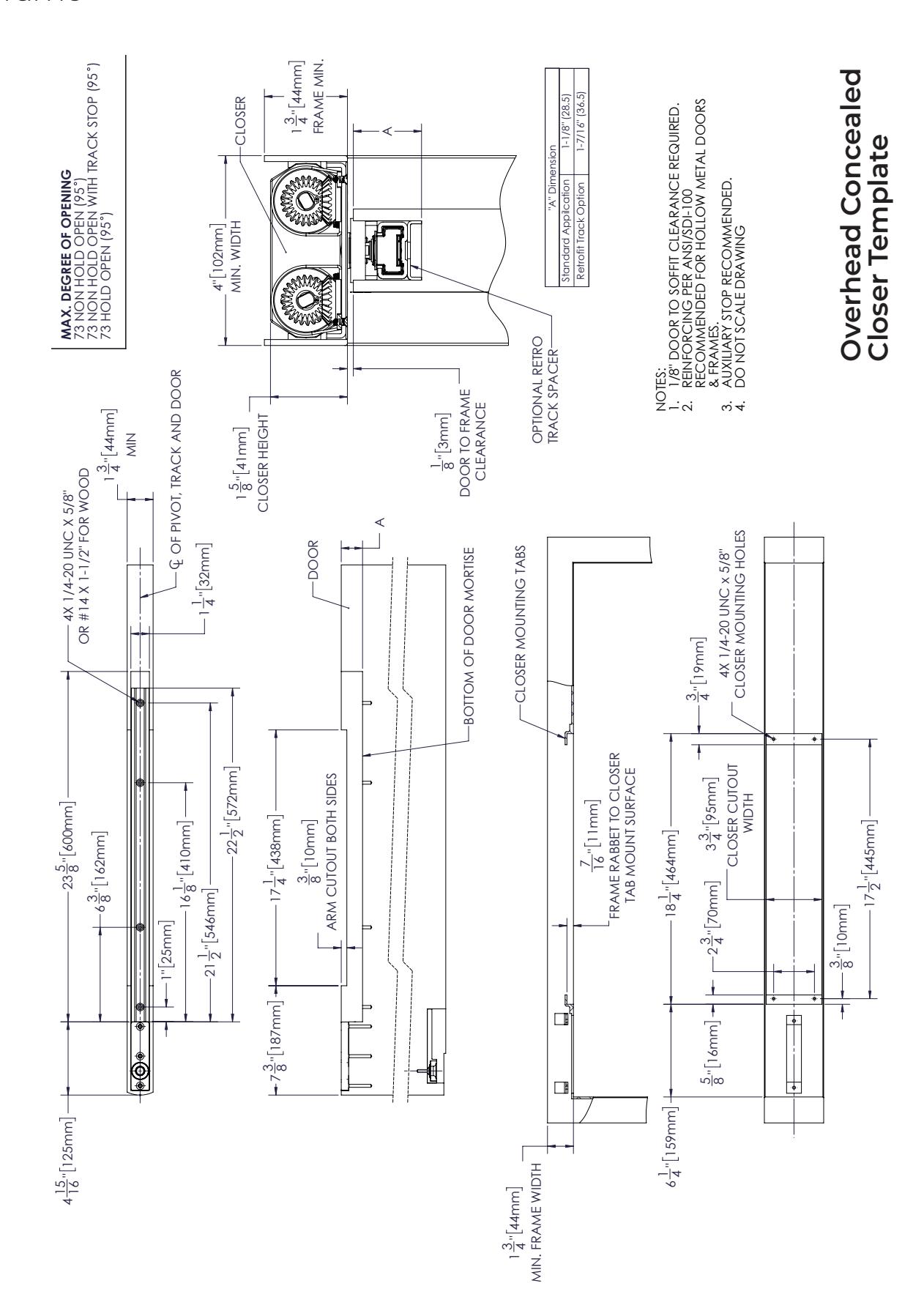
| Overhead Concealed Closer Template | 17 |
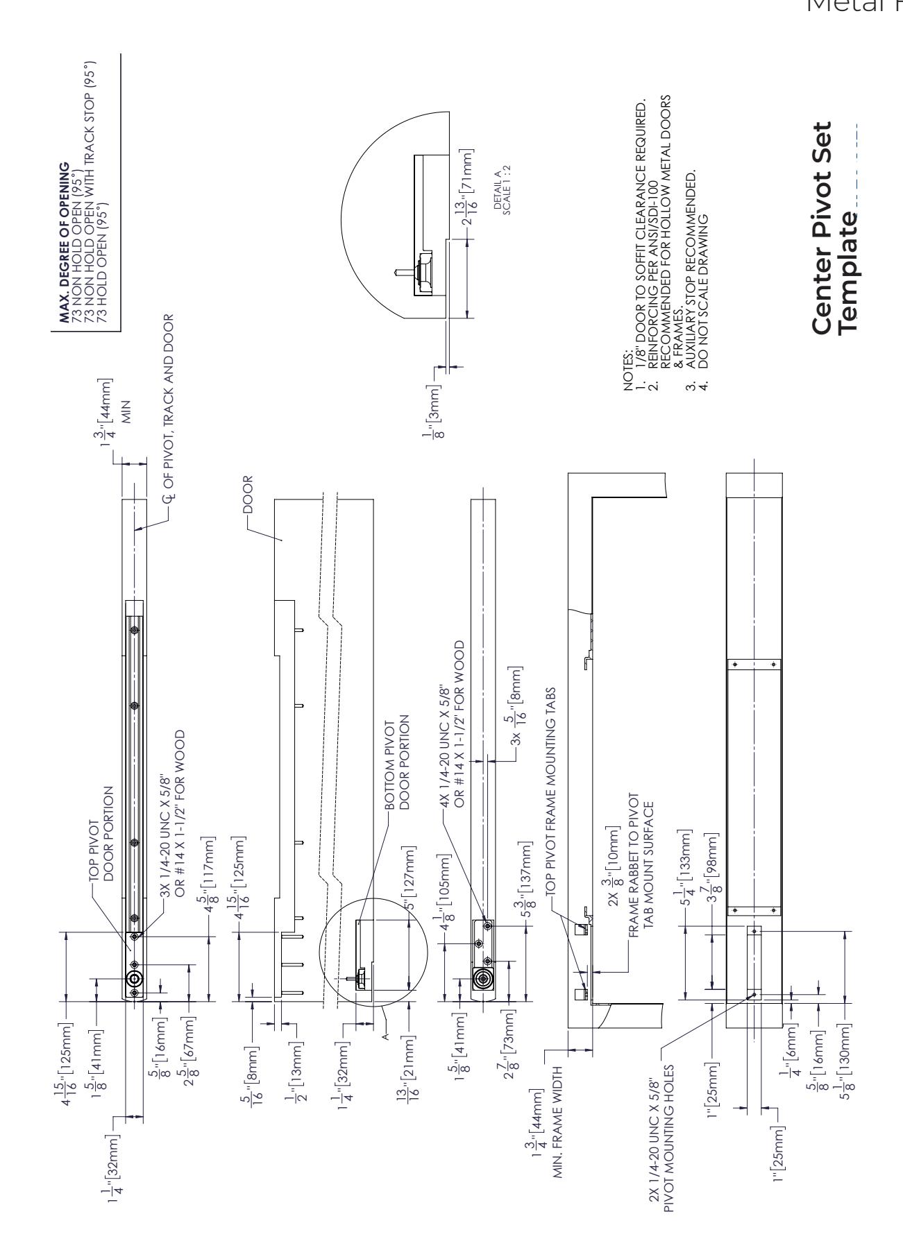
| Center Pivot Set Template | 12 |
IMPORTANT:
- An improperly installed or incorrectly adjusted door closer may cause property damage or personal injury and will void product warranty.
- To avoid personal injury, DO NOT DISASSEMBLE THIS DOOR CLOSER BODY .
- · Door closers must be securely fastened to a prepared door and frame with fasteners provided.
- HOLD OPEN option not permitted to be installed in fire door assemblies.
Before You Begin

- The Americans with Disabilities Act (ADA) requires that doors having door closers have an opening force not to exceed 5 lbf.
- Spring power size adjustment feature may require adjustment to its lowest setting to comply with ADA opening force guidelines.
- ADA compliant closers may not latch doors. Manufacturer does not guarantee latching on lower opening force settings.
- A separate auxiliary door stop, supplied by others, is strongly recommended to avoid damage to door closer in heavy abuse applications.
- Top pivot must be plumb with bottom pivot and door must swing freely before door closer is installed.
- Door and frame must be reinforced for attaching screws.
- All dimensions are given in inches (millimeters).
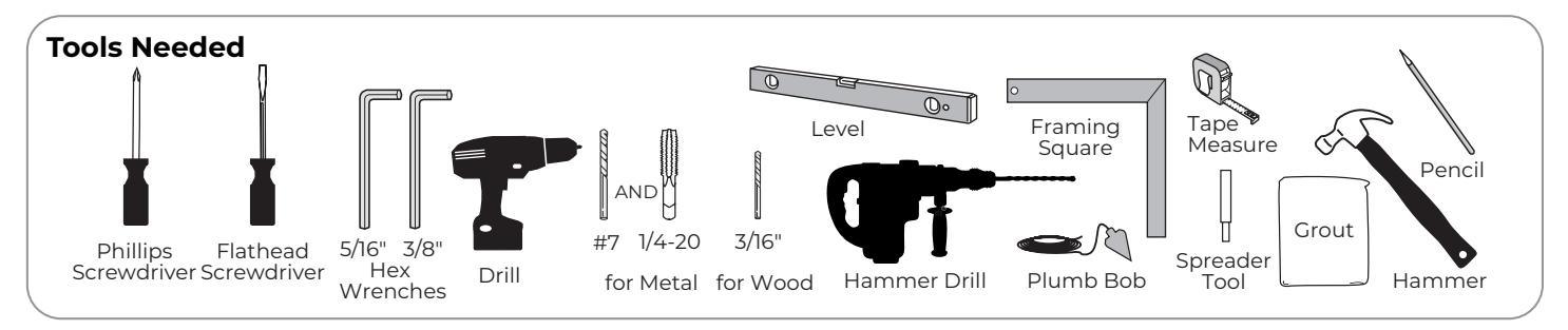
Mounting Hardware
| Mounting Hardware | Door / Frame | Drill | |
|---|---|---|---|
| MANAMANA |
Closer, Top Pivot and Bottom Pivot:
#14 x 1-1/2" |
Wood | 3/16" (4.76mm) |
| Closer, Top Pivot and Bottom Pivot: 1/4-20 × 5/8" | Metal |
Drill #7 (.201 dia. or 5.10mm)
Tap 1/4-20 |
|
|
Track:
#14 x 1-1/4" |
Aluminum or Wood | 3/16" (4.76mm) | |
|
Track:
1/4-20 x 7/16" |
Hollow Metal |
Drill #7 (.201 dia. or 5.10mm)
Tap 1/4-20 |
|

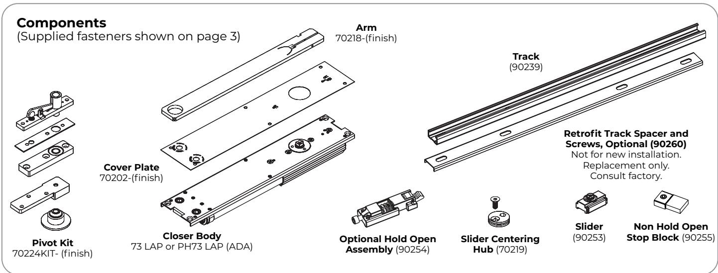
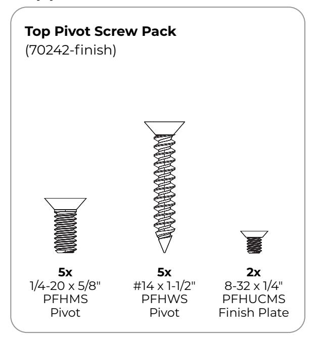
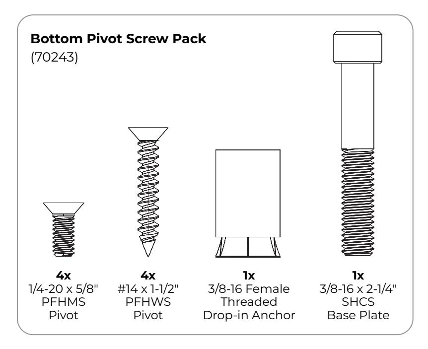
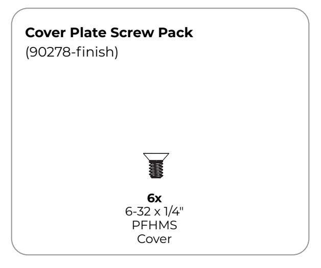
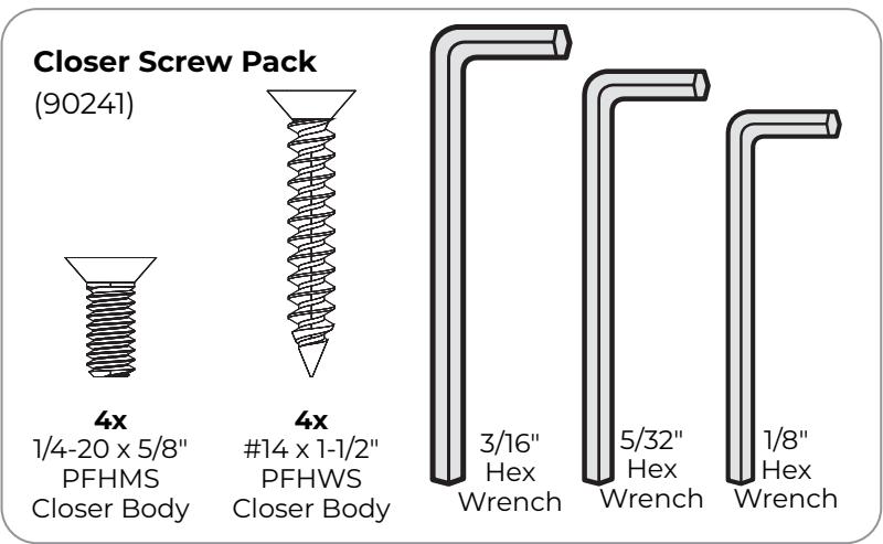
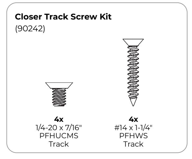
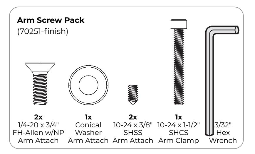
Supplied Fasteners

Installation
A. Prepare frame and door.
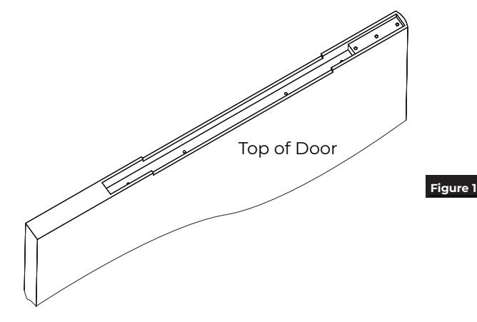
- 1. Using supplied template, prepare and mortise door and head jamb for pivot set. (Figure 1)
- 2. Confirm all cutout dimensions for closer.
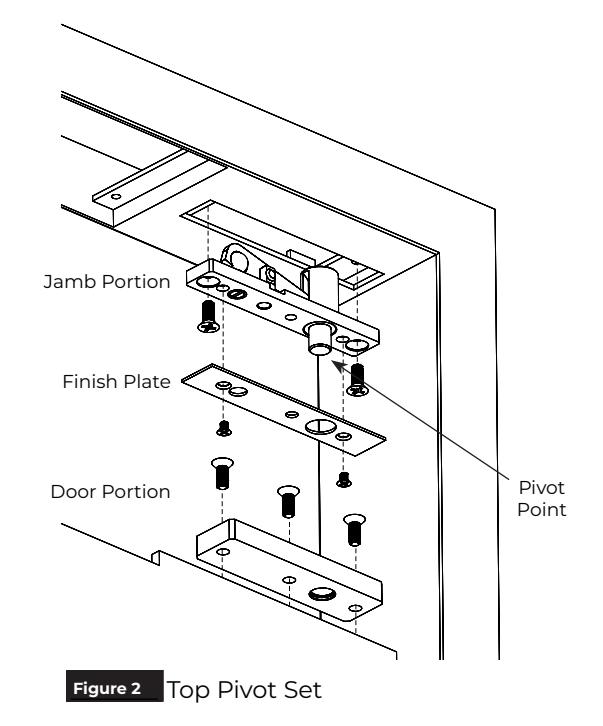
B. Install top pivot set.
- 1. Install jamb portion in prepared frame with two (2) 1/4-20 x 5/8" machine screws. (Figure 2)
- 2. Install door portion in prepared door with three (3) 1/4-20 x 5/8" machine screws or #14 x 1-1/2" wood screws. (Figure 2)
- 3. Attach finish plate to jamb portion with two (2) 8-32 x 1/4" machine screws. (Figure 2)
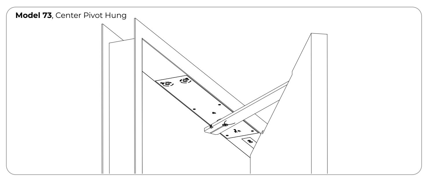
Model 73 Metal Frame

Installation (cont.)
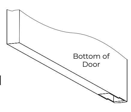
C. Install bottom pivot set.

IMPORTANT: Pivot point of bottom pivot must be plumb with top pivot point. Be sure to properly locate and mark pivot center point of bottom base plate.
1. Install door portion into prepared door with four (4) 1/4-20 x 5/8" machine screws or #14 x 1-1/2" wood screws. (Figure 3)
NOTE: Depth of mortise in door bottom will determine clearance.

- 2. Using a plumb bob attached to top pivot, locate and mark position of base plate on floor.
- 3. Drill 3/4" dia. x 1-3/4" (19 x 44mm) deep hole in floor on center of pivot point for base plate mounting.

IMPORTANT: It is critical to door alignment and proper frame clearance that this anchor hole is positioned within 1/32" of true plumb alignment with the top jamb portion pivot point.
4. With open side up, place drop-in anchor into floor hole. If necessary, tap lightly with hammer until anchor is at bottom of hole.
NOTE: Clean all concrete dust from hole before installing drop-in anchor.
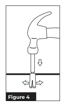
- 5. Set anchor by striking spreader tool with hammer until the sleeve of the anchor is fully expanded. (Figure 4)
- 6. Insert provided base plate screw into anchor to plug opening.
NOTE: Apply grease to base plate screw to prevent grout from sticking to screw and to facilitate removal.
- 7. Grout anchor into place. After grout has set, remove base plate screw.
- 8. Place base plate over anchor and securely fasten to floor with base plate screw.
- 9. If using a threshold, install it at this time.
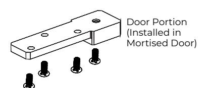
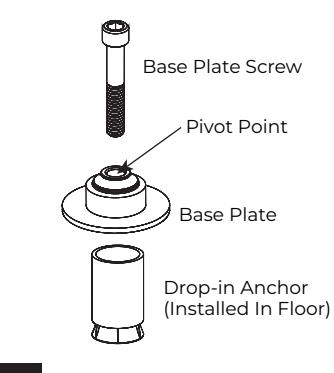
Figure 3 Bottom Pivot


Installation (cont.)
D. Hang door.
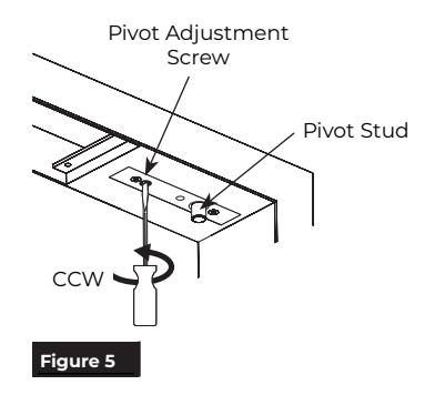
- 1. Ensure pivot stud is fully retracted into pivot by turning pivot adjustment screw counter clockwise with a flathead screwdriver. (Figure 5)
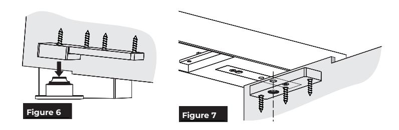
- 2. With door in open position about 90° to jamb, carefully fit door onto bottom pivot at a slight angle. (Figure 6)
- 3. Tip door into vertical position aligning frame portion pivot stud to door portion hole. (Figure 7)
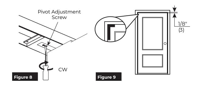
- 4. With top pivot stud aligned with door portion hole, use a flathead screwdriver to turn pivot adjustment screw clockwise to extend pivot stud into door pivot portion. (Figure 8)

IMPORTANT: Fully tighten adjustment screw to ensure pivot stud is fully extended into door portion. There is a door tipping hazard until door is held vertical by pivot stud.
5. Verify frame is square by using a framing square. Gaps between door and frame should be consistent. Gap should be 1/8" (3mm) at jamb and header. (Figure 9)
NOTES: Door should swing freely.
- y If vertical height adjustment is necessary, use shims between door bottom and bottom pivot portion to increase clearance.
- y To decrease clearance, increase mortise depth in bottom of door.
- y To remove door, retract pivot stud and tip door out of vertical position, then lift door from bottom pivot.
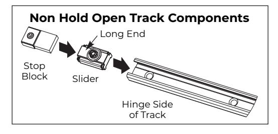
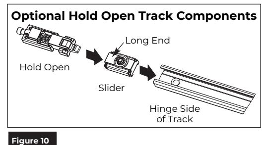
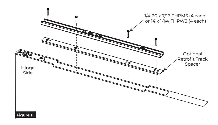
E. Assemble track.
1. Slide track components into track. (Figure 10)
NOTES:
- y All track components must be placed in track before installing track into door.
- y Insert slider into track first.
- y Stop block (or optional hold open) should be last component at hinge side of door.
- y The longer end of slider should be pointed towards hinge side of door.
Approved 2024-05-15

Installation (cont.)
F. Install track to door.
OR
- 1. Make sure slider and track components are installed prior to installing track to door. See Step E.
- 2. Install track into top of door using either four (4) 1/4-20 x 7/16" machine screws for metal doors or four (4) #14 x 1-1/4" wood screws for wood doors. (Figure 11).
NOTE: If necessary, use optional retrofit spacer (replacement application only, consult factory).
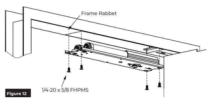
G. Install closer.
1. Install closer into frame with four (4) 1/4-20 x 5/8" machine screws. (Figure 12)
NOTE: Mounting plate should be flush with frame rabbet.
H. Install cover plate.

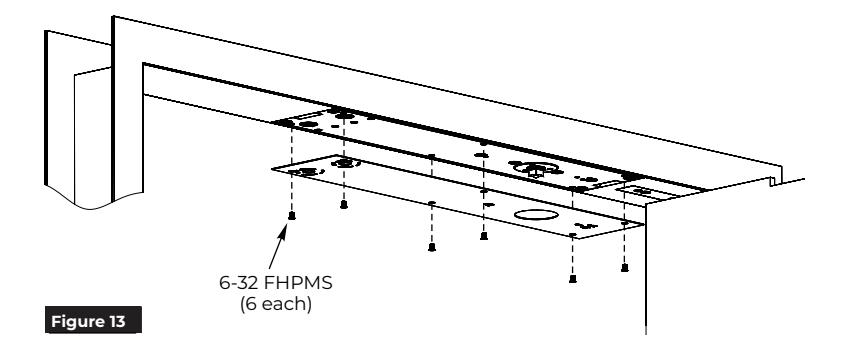
1. Install cover plate to closer body with six (6) 6-32 x 1/4" machine screws. (Figure 13)
I. Attach arm to closer.
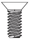
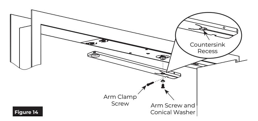
1. Attach arm to closer shaft with 1/4-20 x 3/4" FH-Allen w/Nylon Patch screw and washer. Tighten securely. (Figure 14)
NOTE: Ensure countersink recess side of arm faces down.


Installation (cont.)
J. Attach arm to track.
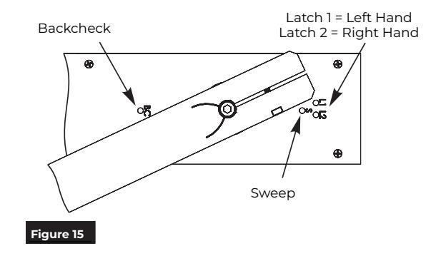
1. With provided 1/8" hex wrench, completely tighten latch and sweep valves by turning clockwise. This will allow for an easier closer-todoor connection. (Figure 15)

CAUTION: Arm will be under strong spring force to return if valves are not tightened completely closed.
2. Open door to about 45° then rotate arm over to door.
NOTES:
- y With latch and sweep valves tightened, arm will maintain position.
- y If door is opened beyond 45°, backcheck may need to be adjusted counter clockwise to easily rotate arm to door position.
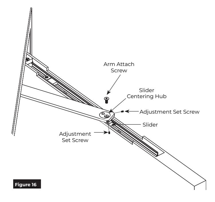
- 3. Install slider centering hub through arm into slider. (Figure 16)
NOTE: Countersink recess should face up.
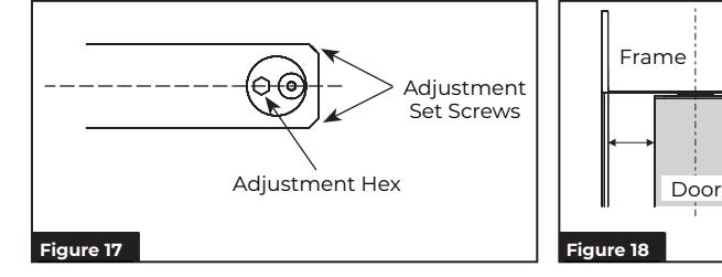
4. Align hub initially as shown and insert two (2) 10-24 x 3/8" adjustment set screws. Turn both set screws just enough to retain slider centering hub. Do not tighten firmly at this time. (Figure 17)
NOTE: Align square shank of slider with square in centering hub for proper fitment.
- 5. Insert arm attach screw, 1/4-20 x 3/4" FH-Allen w/Nylon Patch, and tighten. (Figure 16)
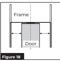
- 6. Open latch and sweep valves to allow door to close and observe door and frame alignment. If door is not centered in frame when closed, reopen door and use 5/16" hex wrench to rotate slider centering hub until door is centered. (Figure 18)
NOTES:
- y DO NOT fully open valves. Valves will leak.
- y Door should be centered in frame when in closed position. Adjust slider centering hub with hex wrench until door and frame are aligned properly then tighten adjustment set screws.
- 7. When door is completely aligned in frame tighten both adjustment set screws.
IS73 Rev 3 04/23
Model 73 Metal Frame

Adjustments
Speed Adjustment
Use provided 1/8" hex wrench to adjust sweep, latch and backcheck valves to control speed of door. (Figure 19)

NEVER completely close backcheck valve. NEVER use backcheck as a dead stop. NEVER fully open valves. Valves will leak.
Do not use a power drill. Warranty will be void.
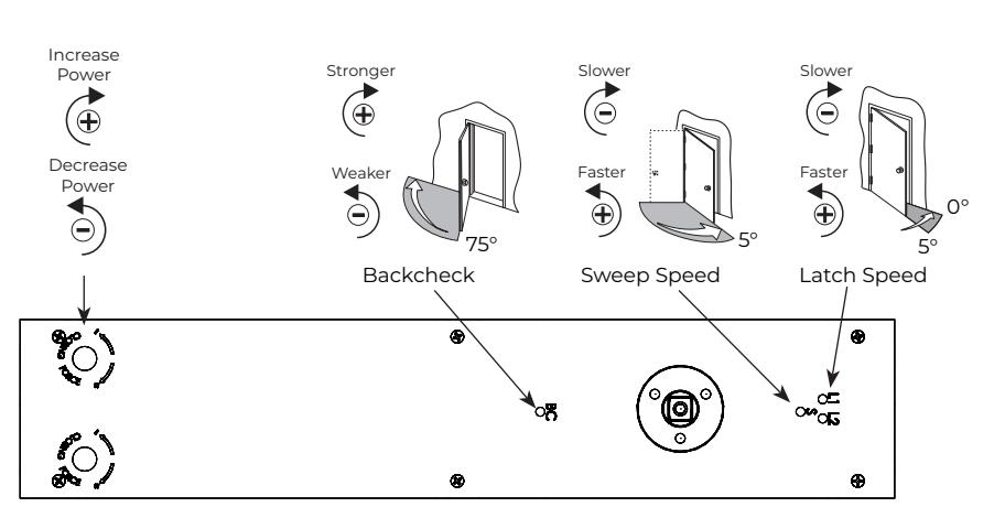
Figure 19
Closing Force Adjustment
If additional force is needed, use 3/8" hex wrench to adjust closing force. (Figure 20)
Use spring adjustment screw that corresponds with hand of swing. (Figure 19)

Do not use a power drill. Warranty will be void.

All 73 Series closers are factory set to minimum force. Adjust closer as necessary for more force taking into consideration door size, weight, positive room pressure, etc.
|
Spring Power Adjustment for Closing Force
(Closer shipped at lowest setting) |
||||||
|---|---|---|---|---|---|---|
| Model PH73DCP | Model PH73DCP Model 73DCP | |||||
|
Closer
Size |
Description |
Approx
# of 360° Turns |
Closer
Size |
Description |
Approx
# of 360° Turns |
|
| ADA |
<5 lbs
Opening Force |
0 | 1 |
2 - 3 lbs
Closing Force |
0 | |
| 1 |
2 - 3 lbs
Closing Force |
15 | 2 |
3 - 5 lbs
Closing Force |
15 | |
| 2 |
3 - 5 lbs
Closing Force |
30 | 3 |
5 -8 lbs
Closing Force |
35 | |
| 3 |
5 - 8 lbs
Closing Force |
50 | 4 |
8+ lbs
Closing Force |
50 | |
Figure 20
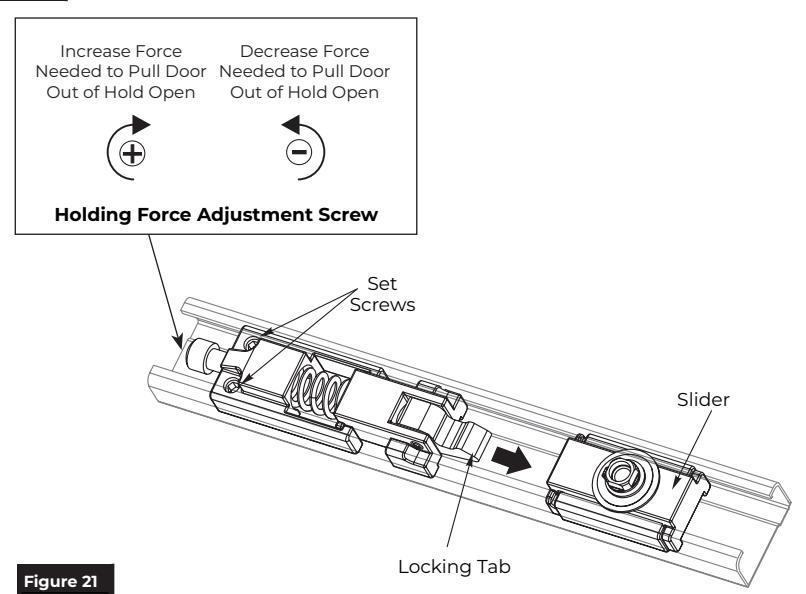
Optional Hold Open Adjustment
1. Insert locking tab of hold open assembly into track slider. (Figure 21)
NOTE: Hold open assembly should be on hinge side of track slider.
- 2. Open door to desired hold open position.
- 3. Tighten hold open set screws to lock down hold open assembly. (Figure 21)
- Pull door in closing direction to disengage hold open assembly and track slider.
- 5. Adjust hold open by turning adjustment screw with provided 3/16" hex wrench. (Figure 21)

NOTE: THIS FEATURE CANNOT BE USED ON FIRE-RATED DOORS
Installation of the Model 73 Overhead Concealed Closer is now complete.

Troubleshooting
| Symptom | Cause | Remedy |
|---|---|---|
| Door won't latch | Spring tension not strong enough |
Increase opening force.
See Adjustments on page 9. |
| Latch speed control not fast enough |
Adjust latch speed valve.
See Adjustments on page 9. |
|
|
Door hung on products other than
center pivots |
Send template for hanging means to
factory. A new installation sheet is re quired. Closer will need to be relocated. |
|
| Arm is not preloaded |
See Step J. Attach arm to track. on
page 8 |
|
| Door is too difficult to open | Spring tension is set too strong |
Decrease opening force.
See Adjustments on page 9. |
Model 73 Overhead Concealed Closer Template Center Pivot Set Metal Frame