Norton Rixson L27 Series Floor Closer, L27, Heavy Duty, 3, 4 Offset, Installation Instructions_2700L
Open the original PDF document
View PDFL27 and L27-180 Heavy Duty Floor Closers
3/4" Offset Pivoted - Handed L180 Top Pivot - Non Handed Installation Instructions


This product can expose you to lead which is known to the state of California to cause cancer and birth defects or other reproductive harm. For more information go to www.P65warnings.ca.gov.
| Door Size | A | B | Max. Lead Thk. |
|---|---|---|---|
| 1-3/4 | 1-1/4 | 1/4 | 9/32–7.14mm |
| 2" | 1-3/8 | 5/16 | 3/8–9.52mm |
| 2-1/4 | 1-1/2 | 3/8 | 15/32–11.90mm |
| 2-1/2 | 1-5/8 | 7/16 | 9/16–14.28mm |
| 3" | 2" | 1/2 | 3/4–19.05mm |
Table based on lead placed in center or door.
Right Hand Shown Conversion from inches to metric: inch x 25.4
- 1. Arm and pivot leaf drilled to receive 2" #14 FHWS or 1" x 1/4-20 FHMS.
- 2. For Wood Doors: Pre-drill arm and top pivot holes to prevent splitting.
- 3. If vertical adjustment is required two 1/16" shims are provided. Place shims between arm and spindle shoulder collar.
- 4. Max degree of opening, trim permitting, is 105°. Suitable reinforcing by others. Lead lining by others.

L27 and L27-180 Heavy Duty Floor Closers
How To Determine Hand of Door
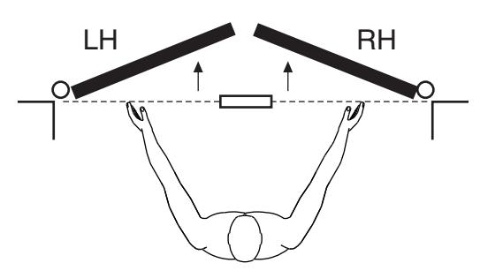
Face a door swinging open away from you. If it opens to the right, it is right hand. If it opens to the left, it is left hand.
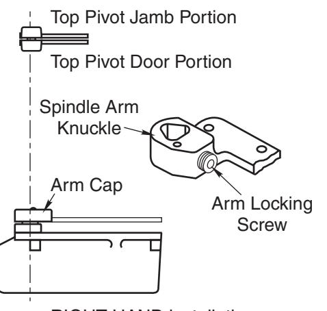
RIGHT HAND installation
IMPORTANT:
Use plumb line to make sure that center line of top pivot pin lines up with center line of closer spindle.
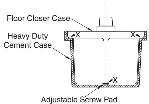
CAUTION:
An adjustable screw pad is provided in this heavy duty cement case for better load distribution. This pad is adjusted so the heavy duty closer case is equally supported by the adjustable pad and the case flange pads at outer corners of case as shown by "X". Pad is staked to keep from coming loose.
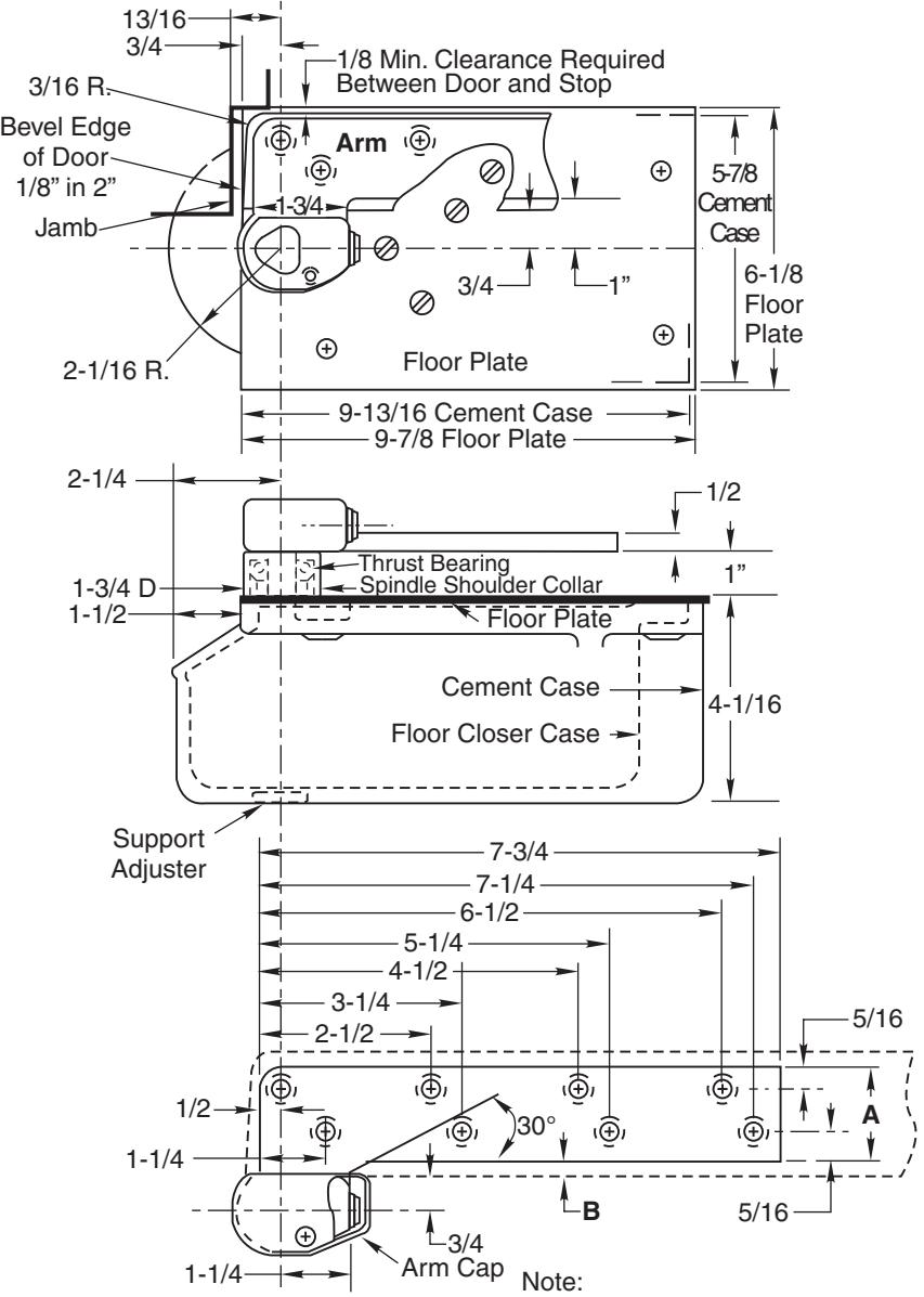
1. Locating Closer
For accurate installation see your dealer for a 185 Quickspotter Kit.
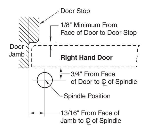
- A. Measure 13/16" out from door jamb.
- B. Allow 1/8" minimum clearance from door stop to door face. Measure door thickness. Add 3/4".
- C. Where lines meet determines center line of closer.
2. Install Cement Case in Floor
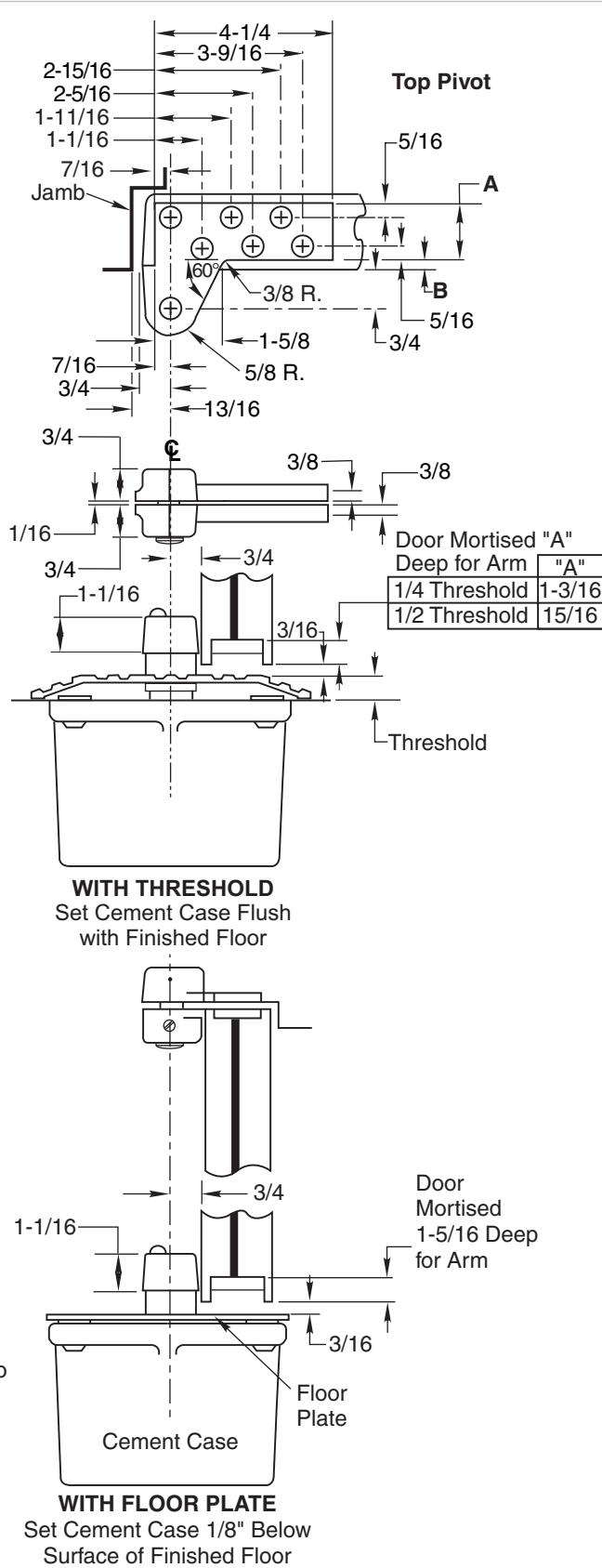
- A. For floor plate application: Cement case is set 1/8" (3.2mm) below floor level.
- B. For threshold application: Cement case is set flush with floor.
- C. Set cement case in floor and block in position.
- D. Case should be parallel with center line of door.
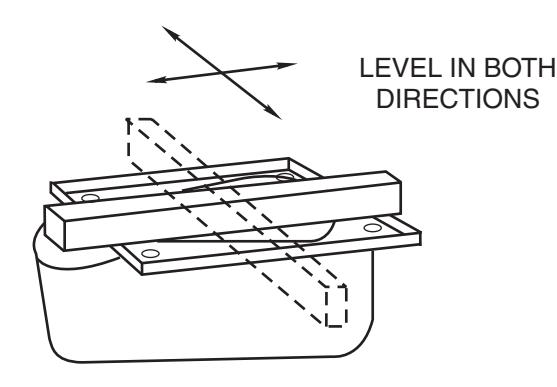
- E. CEMENT CASE SHOULD BE LEVEL. Place levels per Illustration.
- F. Grout in cement case with closer. Cement should not get between closer and case.
3. Install Top Pivot & Closer Arm
- A. Install top pivot in door per template.
- B. Install top pivot in frame per template.
- C. Center line of pivot should line up with center line of closer. Use plumb line as illustrated.
- D. If side pivot is used, see template for intermediate pivot.
- E. Install door closer arm in bottom of door per template.
L27 and L27-180 Heavy Duty Floor Closers

4. Hang Door
Pins point down for RH closer Wrench 4a
Right Hand Shown
4c
CAUTION: Closer is shipped with Closing Speed valve down. DO NOT FORCE VALVE DOWN.
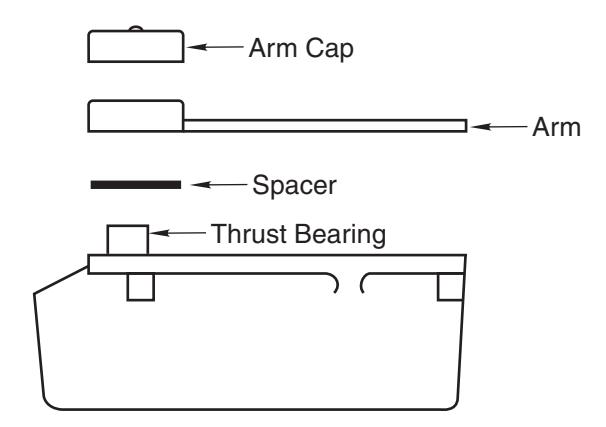
- A. Close down Latch Speed valve. Using wrench, turn spindle until wrench is parallel with center line of closer. (Illustration 4a)Install thrust bearing and spindle shoulder collar.
- B. Set door on closer spindle. DO NOT FORCE DOOR CLOSED WHILE "CLOSING SPEED" VALVE IS TURNED DOWN.
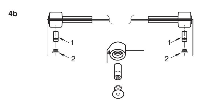
- C. Push item 1 "top pivot pin" into place. Attach "cap" item 2. (Illustration 4b) CAP MUST BE TIGHTENED SECURELY.
- D. Close door to 60° or more and turn Closing Speed valve screw counterclockwise. Door will then close.
- E. Open Closing Speed valve (counterclockwise) one turn. To increase (speed up) closing, open Latch Speed valve (ccw) one turn.
- F. If door drags at floor (or threshold, if used), remove door, insert a spacer (Illustration 4c) and rehang door.
- G. While working door back and forth TIGHTEN ARM LOCKING SCREW SECURELY with wrench furnished.
- H. Put arm cap on closer spindle and secure TIGHTLY with cap screw furnished.
- I. Adjust closing and latch speeds as required for proper closing.
The ASSA ABLOY Group is the global leader in access solutions. Every day we help people feel safe, secure and experience a more open world.

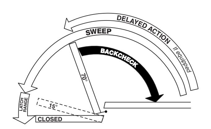
Closer Adjustment
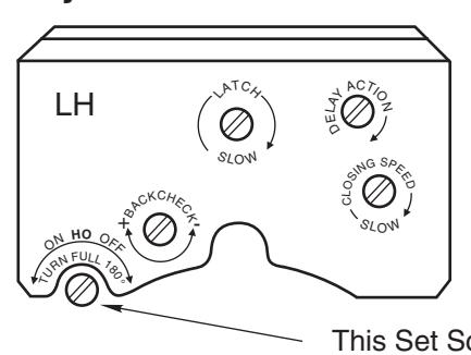
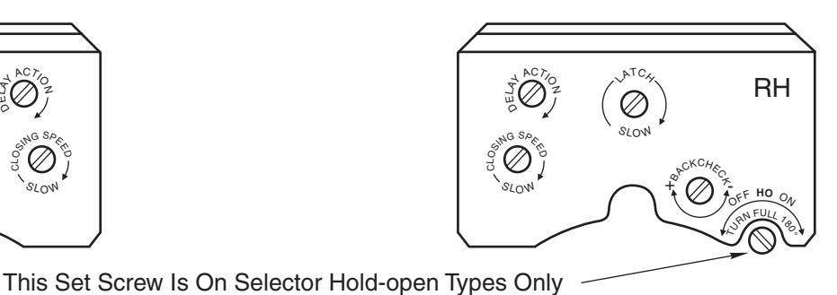
Closing speeds can be adjusted to suit local conditions and requirements. Label on closer face designates the purpose of each adjustment screw. Adjustments are for speed control.
- A. The Delay Action valve allows adjustment from full open to 65° closed position. (Optional)
- The Closing Speed valve allows adjustment from full open to 15° on units without the Delay Action feature.
- C. The Closing Speed valve allows adjustment from 65° to 15° closed position on closers with Delay Action feature.
- Latch valve allows adjustment from 15° to closed position.
- E. Important: Backcheck adjustment must be adjusted to vary resistance from light to firm at 60° of door open. Do not use Backcheck as deadstop. This is an intensity valve not speed control.
Closer Type
This closer is one of three types as follows:
- Non hold-open factory set. No hold-open adjustments.
- Automatic hold-open factory set. No hold-open adjustment.
- Selective (on-off) hold-open label will indicate position of on-off selector screw. When turned "on", closer has automatic hold-open: turned "off", hold-open will not function. Turn full 180°.
Spring Power Adjustments
This closer can be adjusted for increased or decreased spring power.
These adjustments if required should be done by an authorized repair agency.
Repairs, parts replacement or internal adjustments must be done by a Norton Rixson authorized repair agency. Consult NortonRixson.com for an authorized repair agency in your area.
Technical Product Support: Monroe, NC 28112 USA Phone: 800.438.1951 ext: 6030
Techsupport.NortonRixson@assaabloy.com
NortonRixson.com