Norton Rixson Instructions for Activating Switches (501, 502, 505, 506, 507, 531, 532, 533, 534, 535) and Vestib…_80-9360-0100-000
Open the original PDF document
View PDFUSER'S GUIDE
1. Description
The pushplates are designed to fit into standard electrical gang boxes. The faceplate is made of 1/16" thick stainless steel for durability, and has concealed fasteners to minimize vandalism. The pushplates may be hard wired to the door operator or connected radio controlled transmitters.

2. Specifications
| DESCRIPTION | 6" ROUND | JAMB | 4-1/2" SQUARE | 6" SQUARE |
|---|---|---|---|---|
| SIZE | 6.00" X 0.62" | 1.50" X 4.75" X 0.62" | 4.50" x 4.50" x 0.62" | 6.00" x 6.00" x 0.62" |
3. Precautions
- Shut off all power before attempting any wiring procedures.
- Maintain a clean & safe environment when working in public areas.
- Constantly be aware of pedestrian traffic around the door area.
- Always stop pedestrian traffic through the doorway when performing tests that may result in unexpected reactions by the door.
- ESD electrostatic discharge: Circuit boards are vulnerable to damage by electrostatic discharge. Before handling any board ensure you dissipate your body's charge. • Always check placement of all wiring before powering up to insure moving door parts will not catch any wires
- and cause damage to equipment.
- Ensure compliance with all applicable safety standards (i.e. ANSI A156.10/19) upon completion of installation.
-
DO NOT attempt any internal repair of the sensor. Unauthorized disassembly or repair:
- 1. May jeopardize personal safety and may expose one to the risk of electrical shock.
- 2. May adversely affect the safe and reliable performance of the product resulting in a voided warranty.
4. Installation
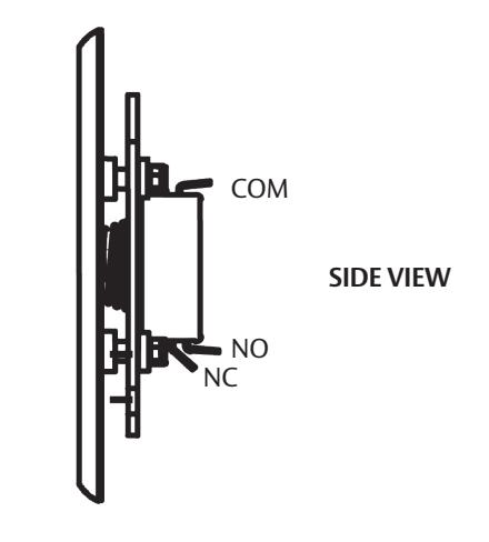
- 1. Wire the pushplate to the door controller or radio controlled transmitter using the NO or NC contacts and common.
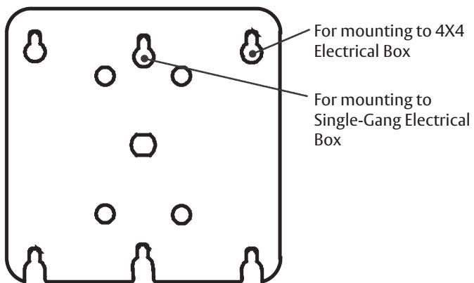
- 2. Finger-tighten the enclosed hex-head screws into the electrical enclosure.
NOTE: The 6" round and the 4-3/4" square pushplate there are two different sized screws. The larger screws (#8) are for the corner locations on 4X4 electrical type boxes and the two smaller screws (#6) are for the single-gang electrical type boxes.
- 3. Place the pushplate holes over the hex-head screws. Use the enclosed hex key to fully tighten the screws.
- 4. Test for proper pushplate activation.
NOTE: Pushplates will need an Adapter Ring to use with the Double Gang Electrical Box.
5. Cleaning Operations
The pushplates are constructed with durable stainless steel and painted with scuff-resistant coatings. To clean the plates, use only a damp, non-abrasive cloth. Regular cleaning with harsh solvents or abrasive materials may cause deterioration of the paint coating. Please make the end-user aware of this procedure.