Norton Rixson HM51 Series Floor Closer, 3, 4 Offset, Single Acting, Handed Installation Instructions_5100HM
Open the original PDF document
View PDFHM51 Floor Closer
3/4" Offset Hinged Single Acting, Handed Installation Instructions


How To Determine Hand of Door
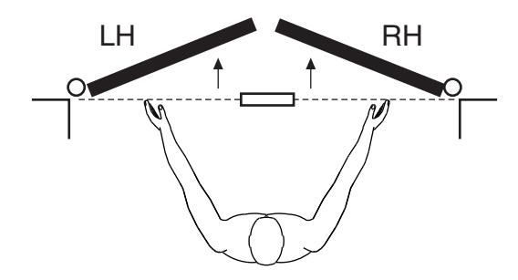
Face a door swinging open away from you. If it opens to the right, it is right hand. If it opens to the left, it is left hand.
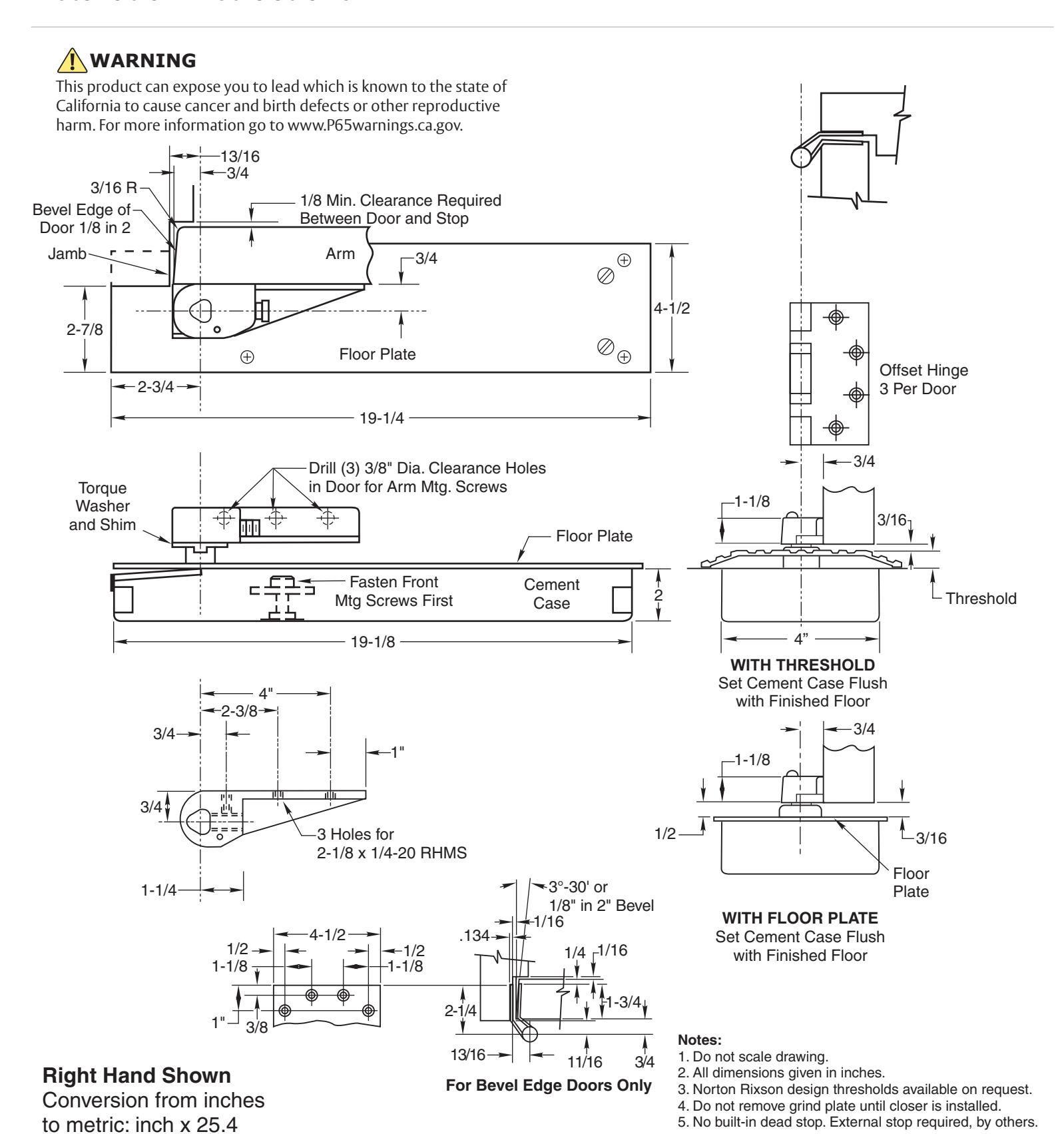
1. Locating Closer
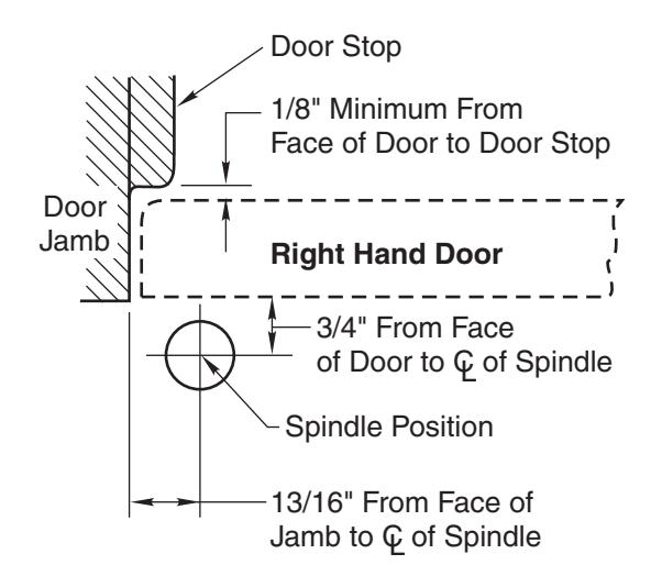
- A. Measure 13/16" out from door jamb.
- B. Allow 1/8" minimum clearance from door stop to door face. Measure door thickness. Add 3/4".
- C. Where lines meet determines center line of closer.
2. Install Cement Case in Floor
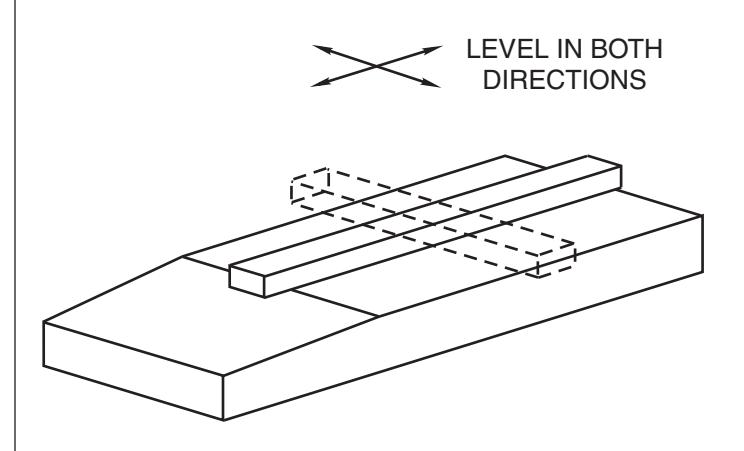
- A. Cement case is set flush with floor.
- B. Set cement case in floor and block in position.
- C. Case should be parallel with center line of door.
- D. CEMENT CASE MUST BE LEVEL. Place levels per illustration.
- E. Grout in cement case with closer. Cement should not get between closer and case.
HM51 Floor Closer

3. Install Offset Hinges
Center line of hinge should line up with center line of spindle. Use plumb line. If center lines don't line up, loosen hold down screws (4) and reposition closer. Tighten hold down screws closest to spindle first. Then tighten screws at cylinder end. Note: Closer must be lifted approximately 1/8" before repositioning.
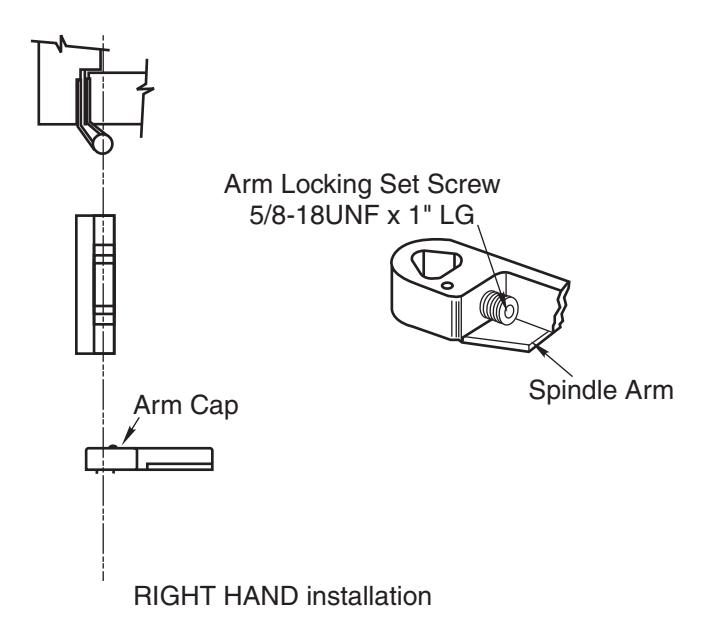
4. Hang Door
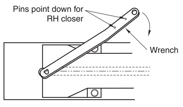
Right Hand Shown
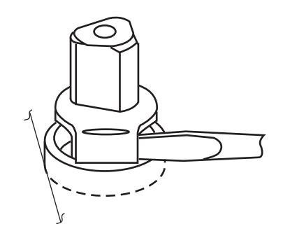
CAUTION: Closer is shipped with "Stroke" valve down. DO NOT FORCE VALVE DOWN.
- A. Turn spindle until wrench is parallel with center line of closer.
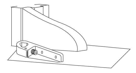
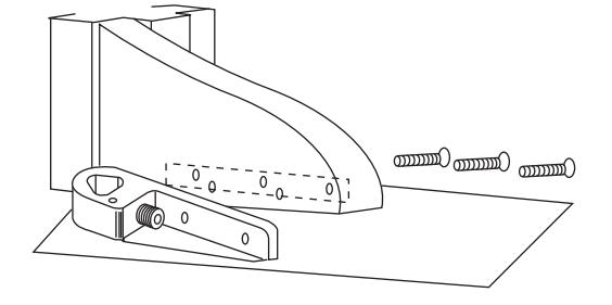
- B. Slip arm on spindle and spot arm mounting holes.
- C. Drill three (3) 3/8" diameter holes in door for arm mounting screws.
- D. Attach arm as shown.
- E. Open Closing Speed and Latch Speed valves (counterclockwise) one turn. Door will then close.
The ASSA ABLOY Group is the global leader in access solutions. Every day we help people feel safe, secure and experience a more open world.

Closer Adjustment
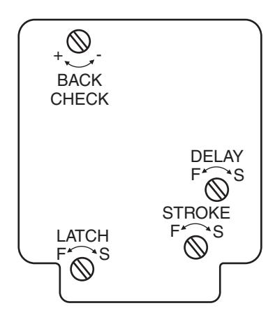
Closing speeds can be adjusted to suit local conditions and requirements. Label on closer face designates the purpose of each adjustment screw. Adjustments are for speed control.
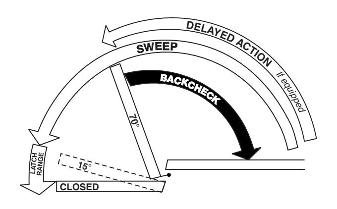
- A. The stroke valve allows adjustment from open to 15°.
- B. The latch valve allows adjustment from 15° to closed position.
- C. IMPORTANT: Back check valve option must be adjusted to vary resistance from light to firm at of door opening.
- D. The delay valve option allows closing speed adjustment from open position to 65°.
Repairs, parts replacement or internal adjustments must be done by a Norton Rixson authorized repair agency. Consult nortonrixson.com for an authorized repair agency in your area.
Closer Removal or Reinstallation
Before removing or installing closer, close down valve screws. When reinstalling, lock closer in hold-open position if provided.
Closer Removal:
- 1. Remove thru-bolts, arm cap and loosen arm locking screw.
- 2. Open door to hold-open or (approx.) 90° and close. (If non hold-open is being removed, insert a flat blade (10" min) screwdriver between spindle and torque washer to prevent spindle from turning.)
- 3. Remove arm, shim and torque washer from spindle.
- 4. With door open, remove threshold.
- 5. Remove closer mounting screws (4) and slide closer out under door.
Closer Reinstallation:
Reverse above procedure when reinstalling closer. Before attaching arm, closer spindle must be in hold-open or rotated to 90°.
Non hold-open closers will require the use of a flat blade (10" min.) screwdriver to rotate the spindle.
Technical Product Support: Monroe, NC 28112 USA Phone: 877.974.2255 ext: 2
Techsupport.NortonRixson@assaabloy.com
NortonRixson.com