Norton Rixson FM972H and FM973H Series Door Releases, Swinging Door Application Installation Instructions_DR100000
Open the original PDF document
View PDF
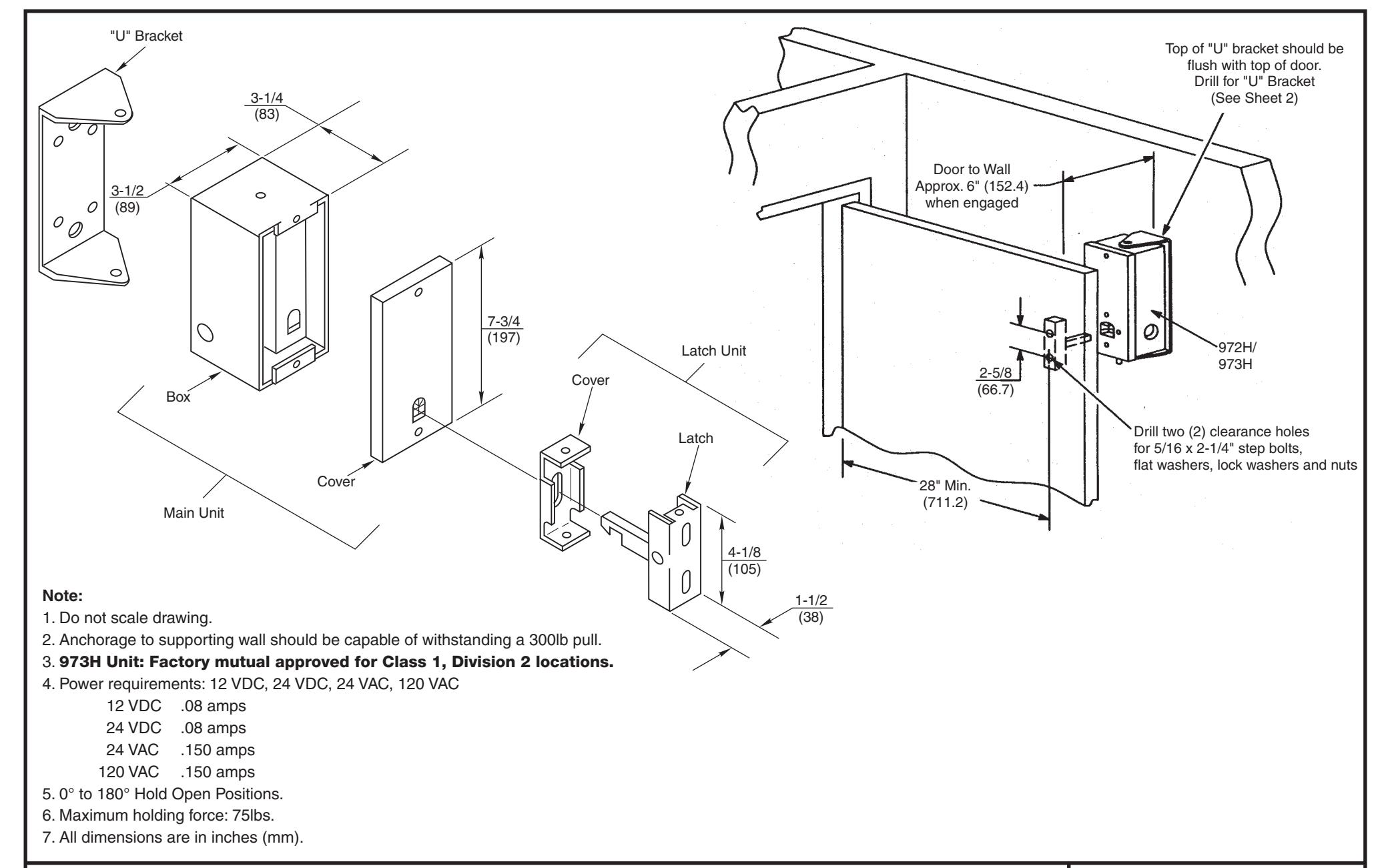
972H Door Release Swinging Door Application
NORTON RIXSON
DR100000 TEMPLATE NUMBER REV
SHEET 1 of 2
4 DATE 06/22
Approved 2022-06-16
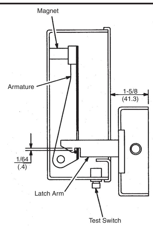
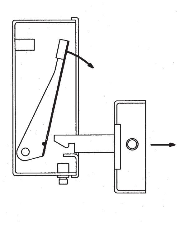
Latch Shown In Engaged Position Latch Shown In Release Position
- 1. Check existing power supply rating against rated voltage on unit. Voltage specifications label located inside of unit in the box cover.
- 2. Remove front covers from both "Main" and "Latch" units.
-
3. Securely bolt "U" bracket to wall. Top of "U" bracket should be flush with top edge of door. Locate "U" bracket so that holder will be approximately 6" (152mm) from edge of door. IMPORTANT: Holder must be a minimum of 28" (711mm) from pivot point of door.
- Use four (4) #20 x 2" lag screws and lockwashers for installation into wood backing.
- Use two (2) #20 x 2" lag screws, lockwashers and rawl plugs for installation into masonry walls. Drill 3/8" (9.5mm) diameter holes for rawl plugs provided.
- Use two (2) 5/16-18 x 3/4" machine screws and lockwashers for metal mounting. Drill and tap 5/16-18 holes.
- 4. Place the main unit in the "U" bracket and fasten using two (2) 1/4-28 x 1/2" hex head machine screws and lockwashers. (For 972H Only: Test switch is on the bottom of the unit.) Open door so that face of door and face of main unit are 1-5/8" (41mm) apart. Align main unit parallel to door.
-
5. Secure latch unit to door using two (2) 5/16 x 2-1/4" step bolts, flat washers and lockwashers. Adjust latch unit for the following:
- a. 1/64" (.4mm) vertical clearance between latch unit and catch on armature. (see illustration)
- b. Latch arm must clear sides fo box cover opening as door swings to closed position.
- 6. Secure all screws and bolts. Replace covers.
972H Door Release Swinging Door Application Installation Instructions
NORTON RIXSON
DR100000 TEMPLATE NUMBER REV
SHEET
DATE
Approved 2022-06-16
4 06/22 2 of 2