Norton Rixson FM 972S and FM 973S Door Release, Sliding Door Application Installation Instructions_DR100010
Open the original PDF document
View PDF
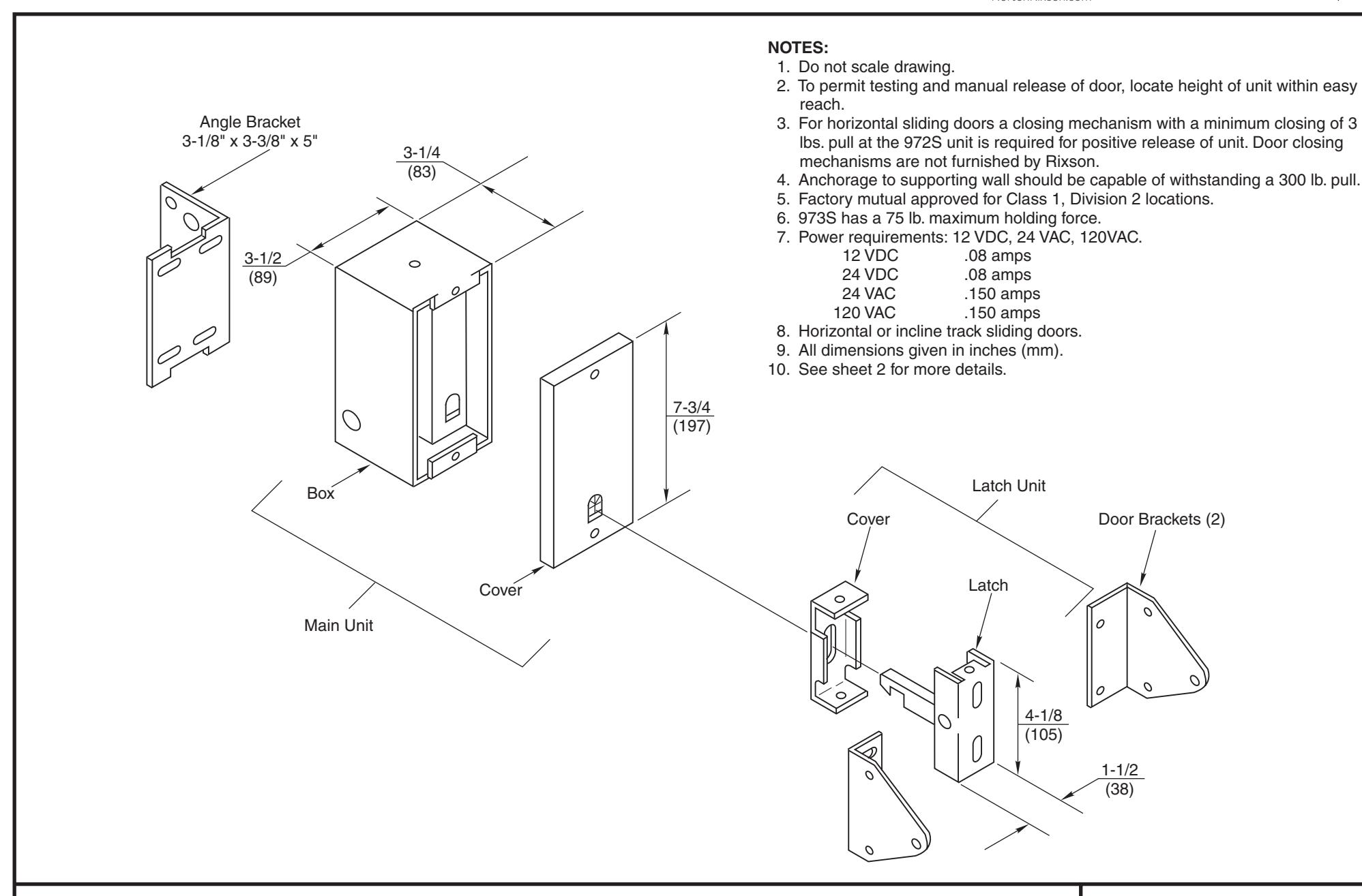
972S Door Release Sliding Door Application
NORTON RIXSON
TEMPLATE NUMBER REV
SHEET
4 DATE 06/22
Approved 2022-06-16
DR100010 1 of 2
- 1. Check existing power supply rating against rated voltage on unit. Voltage specifications label located inside of unit in the box cover.
- 2. Remove front covers from both "Main" and "Latch" units.
-
3. Secure door brackets and latch unit to edge of door as follows:
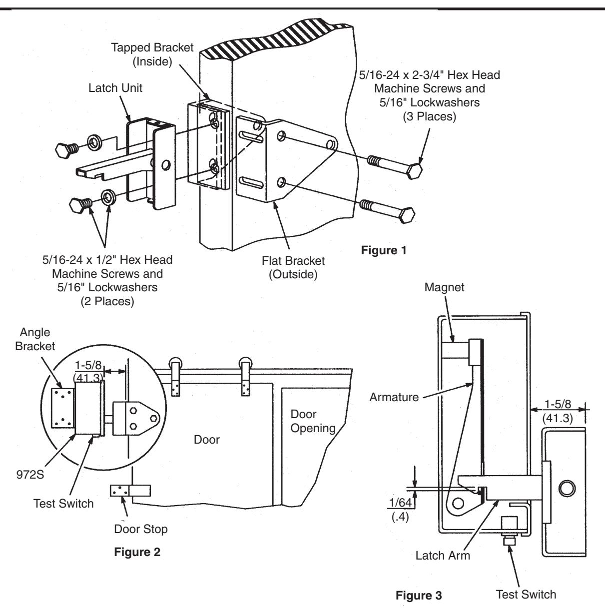
- a. Place door bracket with tapped holes on backside of door. Place flat door bracket on front of door. Mark and drill three (3) 5/16" (8mm) dia. holes through door for the three (3) 5/16-24 x 2-3/4" hex head machine screws. Do not mount brackets to door.
- b. Attach latch unit to brackets using two (2) 5/16-24 x 1/2" hex head machine screws and flat washers (through latch unit). DO NOT tighten screws.
- c. Secure assembled latch unit and door brackets to door using three (3) 5/16-24 x 2-3/4" hex head machine screws and lockwashers. Tighten bracket mounting screws securely.
- 4. Attach angle bracket to main unit using four (4) 1/4-28 x 1/2" hex head machine screws and lockwashers. DO NOT tighten screws. See Figure 2.
-
5. Open door to extreme open position against door stop. Main unit should now be aligned with latch unit as follows:
- a. Align main unit so latch arm passes through the center of the opening in the armature. Unit must be mounted vertically. (Test switch on 972S unit must be towards floor.) Tighten four (4) 1/4-28 x 1/2" hex head machine screws on angle bracket and main unit.
- b. 1-5/8" (41mm) dimension must be maintained between mounting bracket or back side of latch unit and face of 972S. Door must be against door stop.
-
c. Hold unit in this position and mark location for two (2) mounting screws. Drill holes and secure bracket.
- Use four (4) #20 x 2" lag screws and lockwashers for installation into wood backing.
- Use two (2) #20 x 2" lag screws, lockwashers and rawl plugs for installation into masonry walls. Drill 3/8" (9.5mm) diameter holes for rawl plugs provided.
- Use two (2) 5/16-18 x 3/4" machine screws and lockwashers for metal mounting. Drill and tap 5/16-18 holes.
- d. Align latch unit for 1/64" (.4mm) vertical clearance between latch arm and catch on armature. See Figure 3.

972S Door Release Sliding Door Application Installation Instructions
NORTON RIXSON
Latch Shown In Engaged Position
DR100010 TEMPLATE NUMBER REV
SHEET 2 of 2
4 DATE 06/22
Approved 2022-06-16