Norton Rixson Checkmate 99 Series, with Single Point Hold-Open Wiring Instructions_80-9399-0103-015
Open the original PDF document
View PDFRIXSON®
Wiring Instructions
99 Checkmate® Series with Single Point Hold-Open
ASSA ABLOY
Combination Door Closer-Holder and Releasing Device with or without Integral Smoke Detector
INSTALLER: LEAVE INSTRUCTIONS WITH BUILDING OWNER
TO PREVENT ELECTRICAL SHOCK AND EQUIPMENT DAMAGE, DISCONNECT ALL POWER BEFORE BEGINNING. MAXIMUM WIRE SIZE IS 18 AWG. ALL WIRING MUST COMPLY WITH APPLICABLE LOCAL ELECTRICAL CODES, ORDINANCES, AND REGULATIONS.
99 Checkmate® Series
Master Unit - 99-626 / 99-826 Support Unit - 99-726 / 99-926
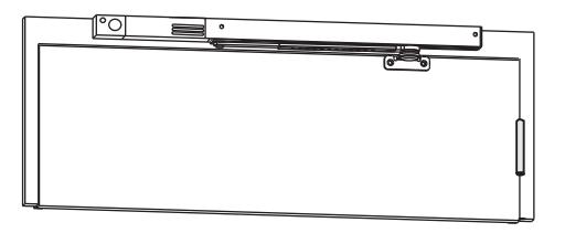
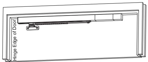
Single Doors
99 Checkmate® Series
Use one "99-626" or "99-826" Master Unit each door or one "99-726" or "99-926" Support unit each door
UTIO
CAUT
Pairs of Doors
99 Checkmate® Series
Use one "99-626" or "99-826" Master Unit and one "99-726" or "99-926" Support Unit for each door leaf (24VDC "99-726/99-926" Support Unit must be used with "99-626/99-826" Master Unit)
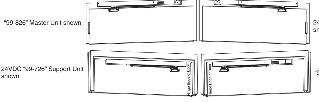
24VDC "99-926" Support Unit shown
"99-626" Master Unit shown
CAUTION:
- 1. Failure to install or adjust properly may result in injury or damage.
- 2. Disconnect all power before beginning installation to prevent electrical shock and equipment damage.
- 3. All wiring must comply with applicable local electrical codes, ordinances, and regulations.
- 4. Maximum wire size is 18AWG.
- 5. These units are not to be used in limited open area applications.
REQUIREMENT:
Power input to unit must be of the same voltage as that listed on the product label: 24VDC for systems where the power input to both the integral smoke detector and the door holder solenoid is supplied from the same circuit (see Pages 4 and 6 thru 8 of these instructions).
Wiring Instructions
RIXSON
Unit Examples:
99 Checkmate® Series:
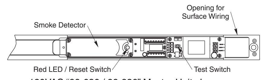

120VAC "99-726/99-926" Support Unit shown
WARNING:

Life safety devices require correct positioning and appropriate selection for the required task. It is the responsibility of the purchaser to select appropriate hardware and provide professional installation. It is the responsibility of the purchaser to insure that NFPA and other applicable fire codes are met. Door release devices function properly only if the door is free to close and is installed correctly.
Smoke detectors will not work without power. AC or DC powered smoke detectors will not work if the power supply is cut off for any reason.
These fire protection devices require correct wiring to function. Devices wired incorrectly may be damaged and therefore not covered under warranty.
All high voltage wiring should be undertaken by a qualified professional licensed electrician. It is the responsibility of the purchaser to insure that installation meets all applicable local and national electrical codes. A detector may not detect a fire developing on another level of a building. For this reason, detectors should be located on every level of the building.
Smoke detectors will not sense fires which start where smoke does not reach the detectors. Smoke from fires in chimneys, in walls, on roofs, or on the other side of a closed door may not reach the smoke detector and activate it.
Smoke detectors cannot last forever. Smoke detectors contain electronic parts. Even though detectors are made to last over 10 years, any of these parts could fail at any time. Therefore, test your smoke detector system per NFPA 72 Chapter 10 at least semiannually. Clean and take care of your smoke detectors regularly. Refer to Page 5 of these instructions for "Smoke Detector Cleaning and Testing". Taking care if the fire detection system you have installed will maintain the reliability of the system.
Smoke detectors have sensing limitations. Smoke detectors used in high air velocity conditions may fail to alarm due to dilution of smoke densities created by such frequent and rapid air exchanges. Additionally, high air velocity environments may create increased dust contamination, demanding more frequent maintenance.
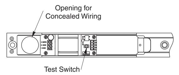
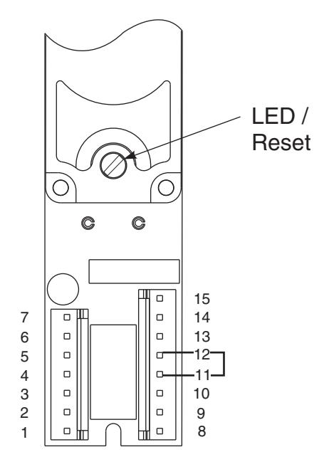
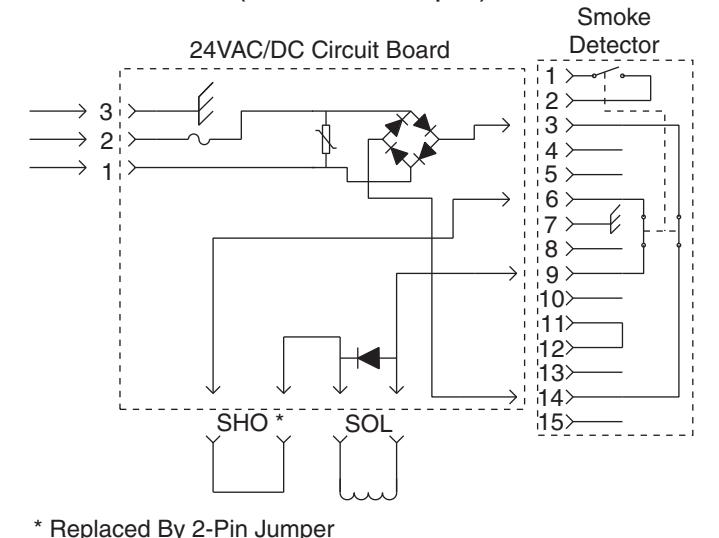
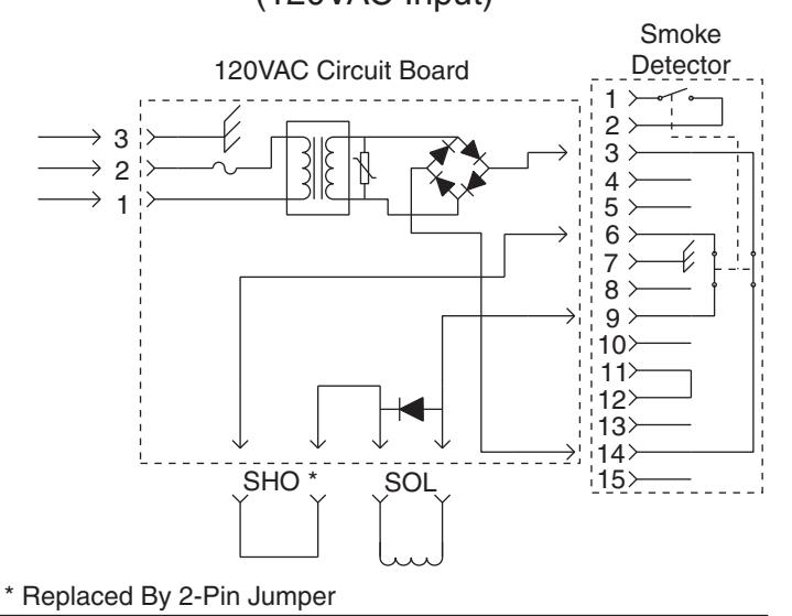
Smoke Detector Terminal Inputs and Outputs
24V input power is applied to terminals 3 (-) and 14 (+) from the circuit board. The red LED flashes every 8 seconds.
Terminals 1 and 2 provide a normally open (alarm) contact. This contact closes when smoke is detected. The red LED illuminates continuously.
Terminals 5 and 13 provide a normally closed supervisory (trouble) contact. This contact opens when power is lost to the detector circuitry. The red LED stops flashing and does not illuminate.
Terminals 6 and 9, if used, provide rectified, unfiltered 24VDC power to an additional door holder solenoid. In an alarm condition, power is removed and the door closes.
Terminals 7 and 8, if used, provide rectified, unfiltered 24VDC power to auxiliary devices when the detector alarms.
Terminal 10 is 24VDC Positive output. It is continuous, rectified, unfiltered 24VDC power used for remote detector interconnect applications.
Terminals 4 and 15 provide interconnections to other detectors (see diagram on Page 8). Up to five smoke detectors may be interconnected. When a single detector alarms, terminal 15 goes high and all interconnected smoke detectors will release their doors. The unit that initiated the alarm will have its LED on. The LED on the other interconnected units will flash as normal. Refer to Interconnection Wiring Diagram for connections.
CONNECTION LIST
| FUNCTION | TERMINAL |
|---|---|
| 24VDC input | 3 (-), 14 (+) |
| Alarm Contacts | 1, 2 |
| Latch (+) | 9 |
| Latch (-) | 6 |
| Aux (+) | 8 |
| Aux (-) | 7 |
| Interconnect (+) | 15 |
| Interconnect (-) | 4 |
| SOLENOID (+) | 9 |
| Trouble contacts | 13, 5 |
| +24VDC output (unfiltered) | 10 |
NOTE: Terminals 4, 6, and 7 are same point
Detector Specifications:
Type: Photo-Electric Smoke Detector complies with UL 228 and UL 268 standards.
Power Requirements: 24VDC +/- 10%. Normal Sensitivity: 2.325 +/- 1.055% / FT.
Contact Ratings:
Alarm and / or accessories (Resistive Load):
2.0 Amps Max @ 24VDC 0.6 Amps Max @ 120VAC
Trouble Contact (Resistive Load):
0.5 Amps Max @ 24VDC
| Max / Min Voltage | Current - Detector | |
|---|---|---|
| 24 VAC | 26.4 VAC Max | 0.028 A Standby |
| 24 VAC | 21.6 VAC Min | 0.059 A Alarm |
| 24 VDC | 26.4 VDC Max | 0.034 A Standby |
| 24 VDC | 21.6 VDC Min | 0.074 A Alarm |
| 120 VAC | 132 VAC Max | 0.033 A Standby |
| 120 VAO | 106 VAC Min | 0.036 A Alarm |
ASSA ABLOY
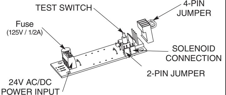
24V AC/DC INPUT CIRCUIT BOARD
(shown with 4-pin jumper for non-detectored units)
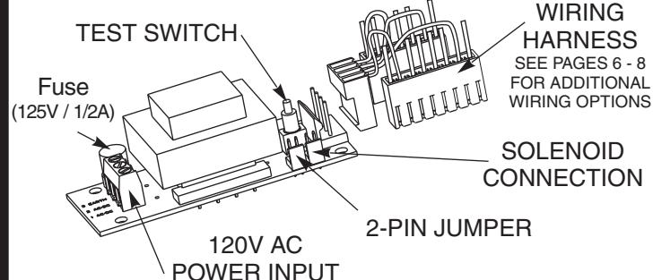
120V AC INPUT CIRCUIT BOARD
(shown with Wiring Harness detectored units)
Support Unit Single Station Wiring Diagram (24VAC/DC Input)
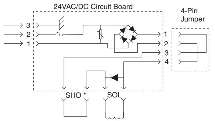
* Replaced By 2-Pin Jumper
Support Unit Single Station Wiring Diagram (120VAC Input)
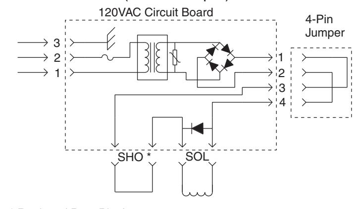
* Replaced By 2-Pin Jumper
Mastert Unit Single Station Wiring Diagram (24VAC/DC Input)
Master Unit Single Station Wiring Diagram (120VAC Input)
All wiring diagrams are shown with circuits energized in stand by mode.
Once alarmed, detector remains in alarm until reset by turning the reset switch on the detector.
Refer to ANSI NFPA 72 for recommended smoke detector applications.
Environmental limits: 100° F(38° C); 95% relative humidity; not for use where high concentrations of corrosive vapors exist. Do not install where air velocity exceeds 30 ft. per minute.
Wiring Instructions
RIXSON<sup>®</sup>
ASSA ABLOY
Checking Procedures:
Turn the power to the unit "On". Red LED light should illuminate at 8 second intervals.
Open the door to the hold open point. The door should hold open. Manually pull door out of hold open and release. The door should close.
Open the door to the hold open position. Press the Test / Reset Switch button on the power supply board. Door should close.
Press the Test / Reset Switch button again. Open the door to the hold open position. Inducing smoke into the smoke detector chamber assembly will bring the unit into alarm. The red LED will be continuously illuminated and the door will close. After clearing the smoke chamber, reset the unit as described below.
Resetting Instructions:
Remote Reset: Cycle main power by turning the facility main power supply OFF then ON. NOTE: If there are other units connected to the same power supply, those doors will close. They will have to be reopened returning them to the hold open position.
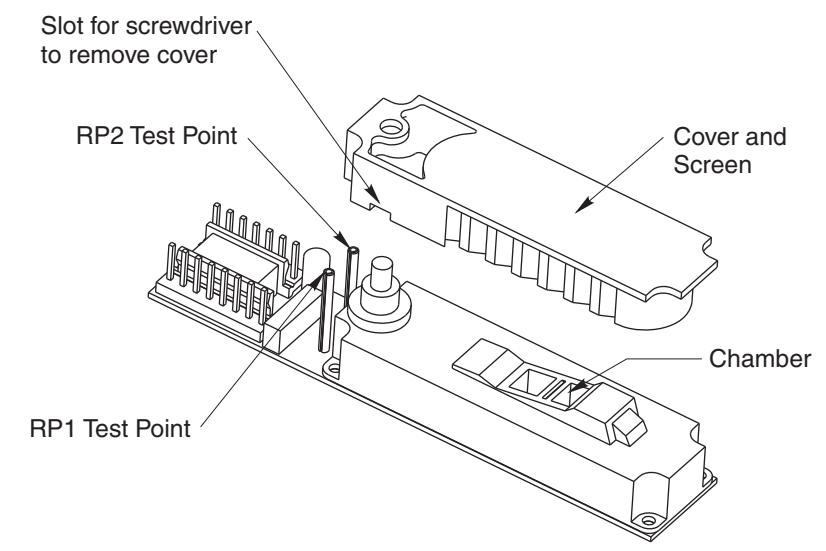
Local Reset: Insert a small flat head screwdriver through the cover and into the slotted light tube on the smoke detector as shown. Turn screwdriver slightly (about 1/8 turn) clockwise until hitting stop and hold for 2 seconds until the Red LED turns OFF. WARNING: Do not force past the stop. Doing so may damage the smoke detector.
Once the detector is reset and the smoke has cleared, the detector's Red LED should flash once every 8 seconds. The door(s) should hold open now.
Maintenance of Smoke Detectors:
It is recommended to clean smoke detectors at least every six months. The frequency of cleaning will depend upon local ambient conditions.
The smoke detector in this door closer-holder has been enhanced with a feature that detects when a smoke-sensing chamber requires cleaning due to dirt and dust. The need for cleaning is indicated by the flashing of the Red LED once per second.
Normal Supervisory Operation - Red LED flashes once every 8 seconds.
Dirty Chamber needs cleaning - Red LED flashes once every second.
Smoke Detection - Red LED is continuously illuminated.
To clean the smoke detector assembly, follow these instructions: (NOTE: Before servicing the system, notify the proper authorities that the smoke detector system is undergoing maintenance and will be temporarily out of service. Disable the zone undergoing maintenance to prevent unwanted alarms.)
Remove detector cover and screen assembly using a standard screwdriver. Turn the screwdriver in the cover slot to loosen the cover and carefully rock the cover back and forth until it snaps out of place. See slot location below. Inspect chamber for particles and dust. Vacuum the screen, cover, and photo chamber. Then use clean, compressed air to loosen and blow out any remaining debris.
Before reassembling the detector, be sure all parts are free of dust and debris.
Replace cover and screen, aligning cover snaps. Press cover onto chamber until it snaps into place. Measure and record the test voltage at test points RP1 and RP2 (see below). If the smoke detector is operating normally and was cleaned effectively, the test voltage will be greater than .90VDC and less than 1.58VDC. The test voltage will increase with dust accumulation in the smoke sensing chamber. A difference in test voltages over time will provide and indication of dust accumulation.
Enable the system and inform proper authorities that system is operational.
ASSA ABLOY
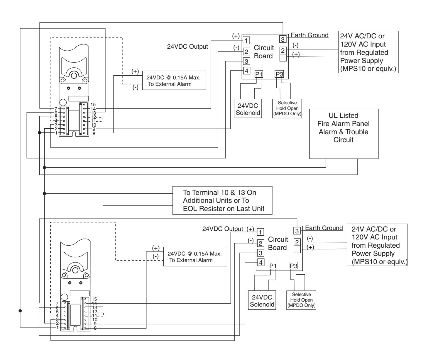
MASTER WIRING DIAGRAM FOR 4-WIRE (CLASS A) SYSTEM WITH ALARM PANEL MONITORING
The alarm circuit monitors if smoke is detected
The detector trouble circuit monitors if power is lost to the detector.

Notes:
End of Line (EOL) resistor determined and supplied by others.
Terminal numbers shown correspond to position numbers of terminal strips on detector. Additional units may be added as required based on this schematic. See electrical data sheet. Do not overload circuits.
All wiring connections use standard wiring practice conforming to local wiring codes.
ASSA ABLOY
MASTER WIRING DIAGRAM FOR 2-WIRE (CLASS B) SYSTEM WITH ALARM PANEL MONITORING
The alarm circuit and trouble circuit monitor if smoke is detected
Notes:
End of Line (EOL) resistor determined and supplied by others.
Terminal numbers shown correspond to position numbers of terminal strips on detector. Additional units may be added as required based on this schematic. See electrical data sheet. Do not overload circuits.
All wiring connections use standard wiring practice conforming to local wiring codes.
Wiring Instructions
Wiring Diagram for Master to Slave / Companion
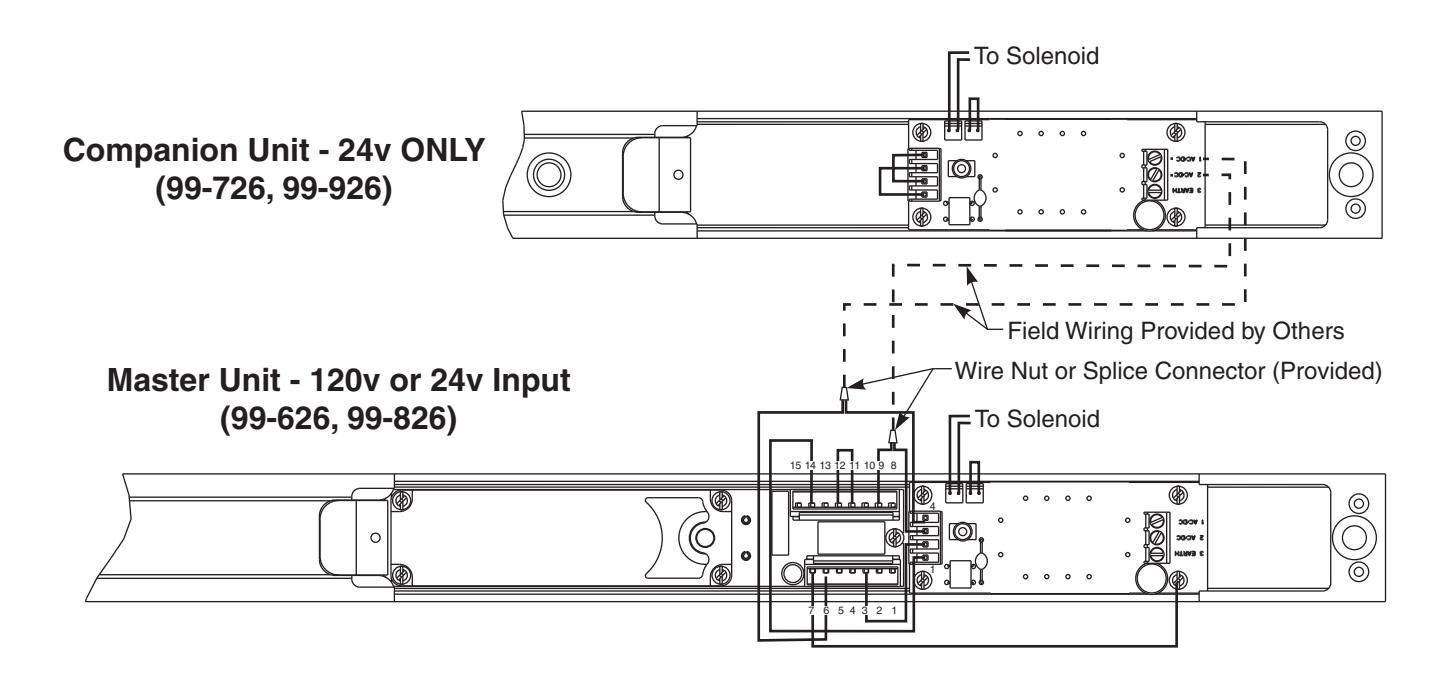
| Circuit Board | Detector Board | |
|---|---|---|
| Connector (Red 4-Pin) | Connector (White 7- & 8-Pin) | |
| 1 — | 14 | |
| 2 ——— | 3 | |
| 3 — | 9 | |
| 4 | 6 | |
| (Factory Wired) | ||

3000 Highway 74 East • Monroe, NC 28112 Tel: (800)-457-5670 www.rixson.com
ASSA ABLOY, the global leader in door opening solutions