Norton Rixson 991M Electromagnetic Door Holder & Release Installation Instructions_DR100225
Open the original PDF document
View PDF
Notes:
- 1. Do not scale drawing.
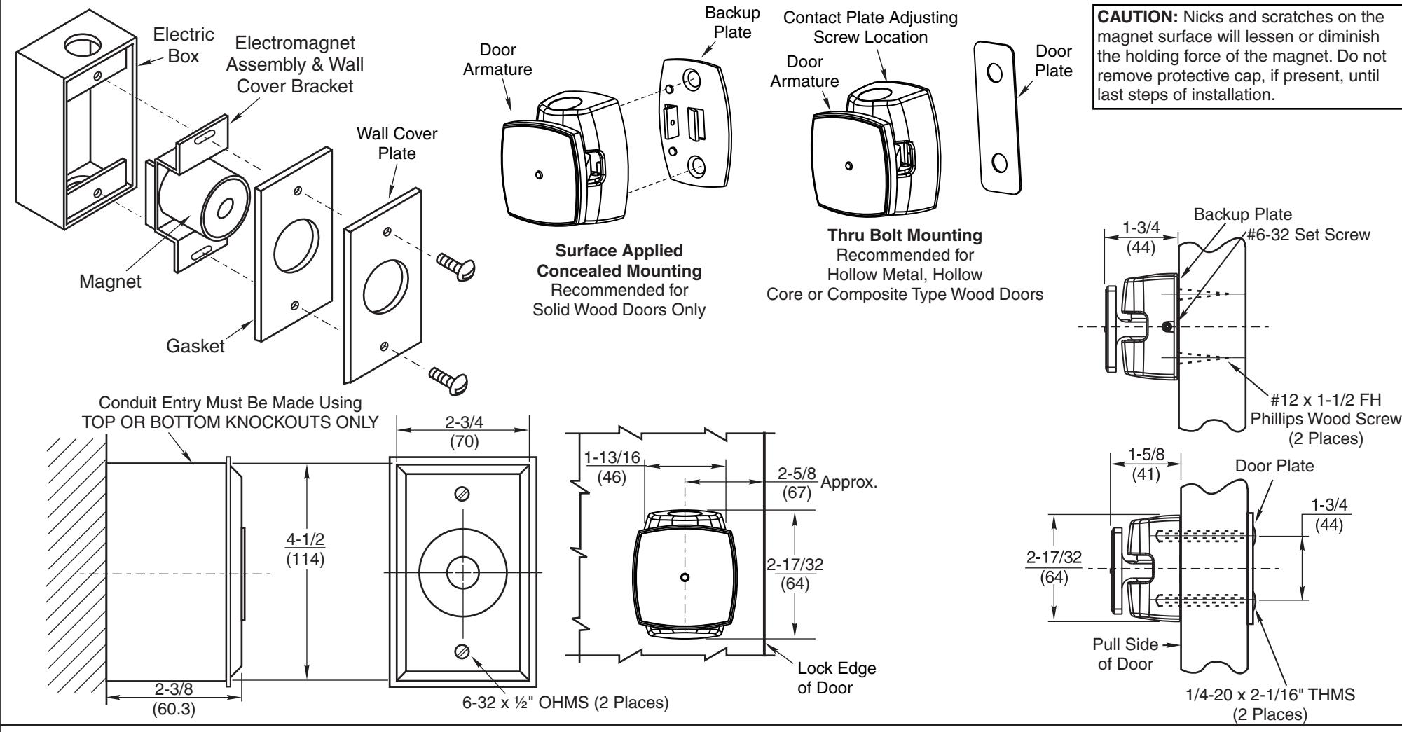
- 2. Total projection 1-1/8" (29mm). (Includes Electromagnet, Armature Assembly and Wall Cover plate.)
- 3. Power requirements: 12VAC, 24VAC, 24VDC, 120VAC, 240VAC.
- 4. See step 1 of sheet 2 for Single Gang Electric Box location. Anchor Electric Box to withstand a minimum 50 lb. pull. Electric Box shown installed in vertical position.
- 5. IMPORTANT: Check line voltage against voltage specifications on back side of magnet
- assembly before installation.
- 6. Door closing mechanism should have a 3 lb. closing force at the degree of door opening where door armature and electromagnet engage.
- 7. Mounting of Electric Box should be reinforced to withstand shock of door opening. Failure to do so will cause box anchors to work loose.
- 8. All dimensions given in inches (mm).
- 9. See sheet 2 for more details.

991M Door Release
TEMPLATE NUMBER REV
SHEET
DATE 01/22
Approved 2022-06-16
DR100225 2 1 of 2
STEP 1 – Location of Electric Box
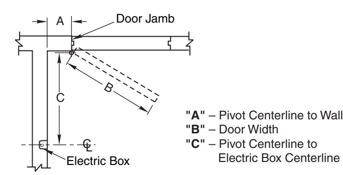
- 1. To locate Electric Box use table below.
- 2. Determine door width (Dim. "B"). Measure pivot centerline to wall (Dim. "A"). Find dimension "C" in table. Example:
Pivot centerline to wall ("A") = 10" (25.4cm)
Door Width ("B") = 36" (91.4cm)
Electric Box Centerline ("C") = 33" (83.8cm)
3. If "A" or "B" falls between the numbers listed in table allow for difference.
Example:
Pivot centerline to wall ("A") = 7" (17.8cm)
Door Width ("B") = 36" (91.4cm)
Electric Box Centerline ("C") = 33-5/8" (85.4cm)
- 4. If dimensions "A" and "B" intersect in shaded area of table DO NOT INSTALL ELECTRIC BOX. The degree of door opening will not permit proper alignment between armature and wall magnet.
- 5. Height to be determined by others. Suggested height is not over 6'0" (1.8m).
- 6. Check degree of door opening in table and coordinate with door closers and other door hardware.
- 7. Total projection of door hardware must not project more than 1-5/8" (41.3mm) on pull side of door.
Location of Electric Box
| Door Width "B" | ||||||||||||||||||||||
|---|---|---|---|---|---|---|---|---|---|---|---|---|---|---|---|---|---|---|---|---|---|---|
| Dim. | 28" (711) | 30" (762) | 32" (813) | 34" (864) | 36" (914) | 38" (965) | 40" (1016) | 42" (1067) | 44" (1118) | 46" (1168) | 48" (1219) | |||||||||||
| "A" | "C" | Deg. | "C" | Deg. | "C" | Deg. | "C" | Deg. | "C" | Deg. | "C" | Deg. | "C" | Deg. | "C" | Deg. | "C" | Deg. | "C" | Deg. | "C" | Deg. |
|
2"
(51) |
26"
(660) |
92° |
28"
(711) |
92° |
29-7/8
(759) |
92° |
32"
(813) |
93° |
34-1/8
(867) |
93° |
36"
(914) |
92° |
37-7/8
(962) |
92° |
40"
(1016) |
93° |
42"
(1067) |
93° |
43-7/8
(1114) |
92° |
45-5/8
(1159) |
92° |
|
4"
(102) |
26"
(660) |
97° |
28"
(711) |
96° |
29-7/8
(759) |
96° |
32"
(813) |
95° |
34-1/8
(867) |
95° |
36"
(914) |
95° |
37-7/8
(962) |
95° |
40"
(1016) |
95° |
42"
(1067) |
95° |
43-7/8
(1114) |
94° |
45-5/8
(1159) |
94° |
|
6"
(152) |
25-5/8
(651) |
102° |
27-5/8
(702) |
101° |
29-5/8
(753) |
100° |
31-3/4
(807) |
99° |
33-3/4
(857) |
98° |
35-3/4
(908) |
97° |
37-3/4
(959) |
97° |
39-7/8
(1013) |
97° |
41-7/8
(1064) |
97° |
43-3/4
(1111) |
97° |
45-1/2
(1156) |
97° |
|
8"
(203) |
25-1/8
(638) |
106° |
27-1/4
(692) |
105° |
29-1/4
(743) |
104° |
31-3/8
(797) |
103° |
33-1/2
(851) |
102° |
35-1/2
(902) |
101° |
37-3/8
(949) |
101° |
39-1/2
(1003) |
101° |
41-1/2
(1054) |
101° |
43-3/8
(1102) |
100° |
45-1/4
(1149) |
99° |
|
10"
(254) |
31"
(787) |
105° |
33"
(838) |
106° |
35"
(889) |
105° |
37"
(940) |
104° |
39-1/8
(994) |
104° |
41-1/8
(1045) |
104° |
43-1/8
(1095) |
103° |
45"
(1143) |
102° | ||||||
|
12"
(305) |
42-5/8
(1083) |
105° |
44-1/2
(1130) |
104° | ||||||||||||||||||
Dimensions given in inches (mm).
991M Door Release Location Sheet
NORTON RIXSON
TEMPLATE NUMBER REV
SHEET
DATE
DR100225 2 01/22 2 of 2