Norton Rixson 8000 Series Door Closer UNI Stop Holder Installation Instructions_80-9380-2214-020
Open the original PDF document
View PDFUnitrol
Installation Instructions
80-9380-2214-020 Rev 3 (05-24)
UNI Stop/Holder
| Non Hold Open | Hold Open | Sizing | |
|---|---|---|---|
| Series No.* | UNI J8300 | UNI J8300H | 2, 3, 4, 5 or 6 |
| UNI J8301 | UNI J8301H | Multi-Size 1 thru 6 | |
| UNI J8500 | UNI J8500H | 2, 3, 4, 5 or 6 | |
| UNI J8501 | UNI J8501H | Multi-Size 1 thru 6 |
* These series have a DELAYED ACTION CLOSING option available that is identified with a "DA" suffix to the series number.

The closing force for these series door closers is adjustable from a size 1 to a size 6, as outlined in ANSI Standard A156.4. When these series of door closers are installed and adjusted to conform to ADA reduced opening force requirements (5 lbs max.) for interior doors, they may not have adequate closing
force to reliably close and latch the door. Power adjustments charted on Page 4 are recommended where possible, to ensure proper door control.
CAUTION
An incorrectly installed or improperly adjusted door closer can cause property damage or personal injury. These instructions should be followed to avoid the possibility of misapplication or misadjustment.
- Always use template covering door-opening-angle desired, correct door-thickness and frame-reveal, and door-hanginghardware being used. Template dimensions in these instructions (page 2) cover frame reveals to 7-3/8" (187mm) in opening with 1-3/4" (44mm) thick doors hung on 4-1/2" (114mm) wide template-hinges (figure 2), 3/4" (19mm) offset-pivots (figure 2) or center-pivots (figure 3).
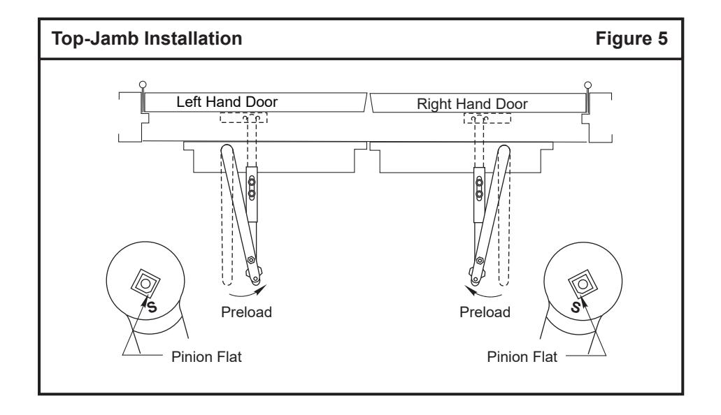
- Check hand of door: right or left (see figure 5, page 3). Make sure that door opens the full angle desired and latches without any binding action or interference. Note that holdopen units will require that door swing five (5) degrees past hold-open point, to dead-stop position.
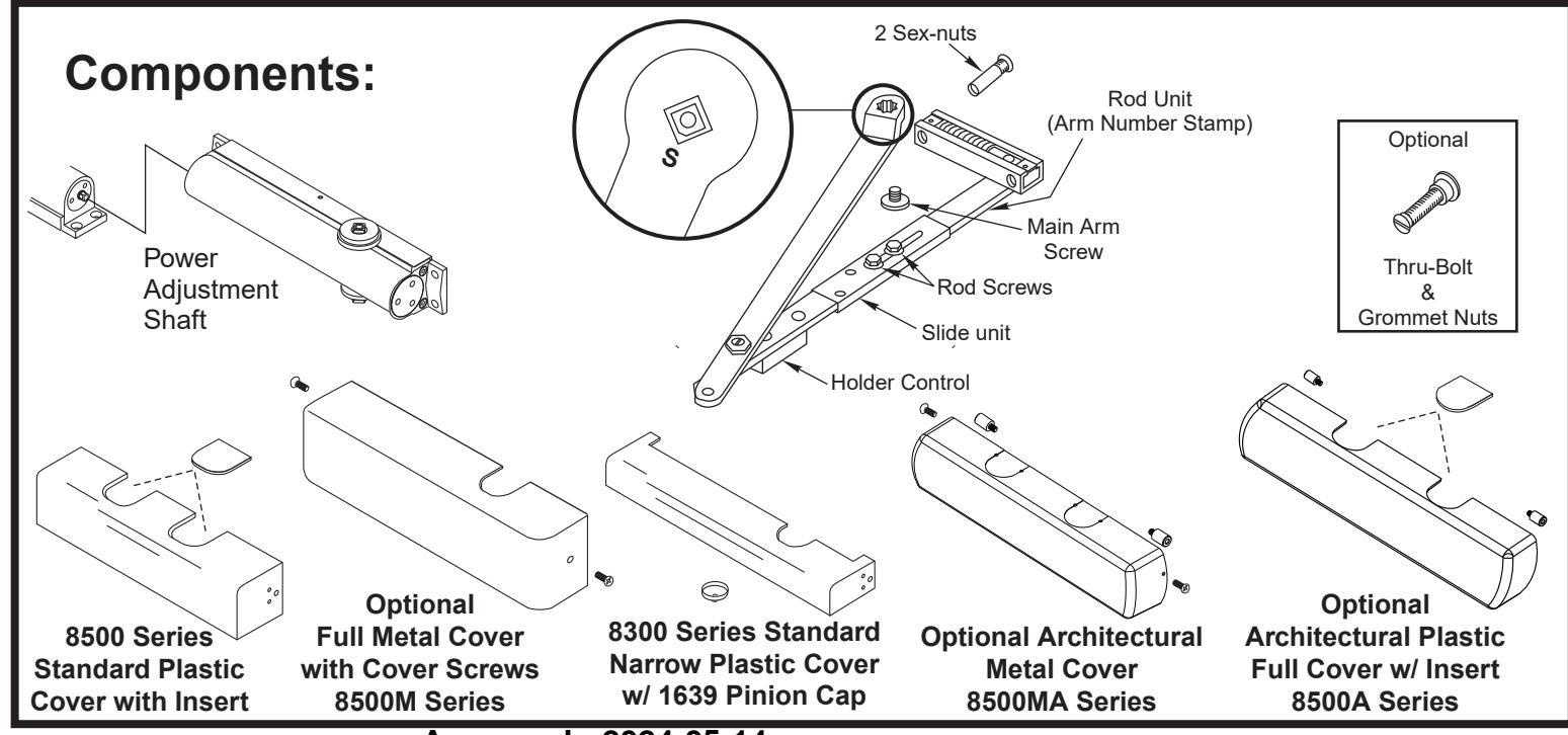
- It is suggested that sex-nuts and bolts be used to mount arm-foot and to mount closer to flush partitions.
- Top Jamb Unitrols are supplied with arm rod units according to frame-reveal. An arm number is stamped on the arm rods, as shown on Figures 2 and 3 (page 2).
Power Adjust
Use 5/16" Socket or Adjustable Wrench for this Adjustment
Power Adjustment Chart for J8301(H) / J8501(H) ONLY
| Number of Turns Required | ||||||||||
|---|---|---|---|---|---|---|---|---|---|---|
| DOOR | MAXIMUM DOOR SIZE | |||||||||
|
32"
(0.85M) |
36"
(0.90M) |
42"
(1.00M) |
48"
(1.20M) |
|||||||
|
Interior
Door |
4 | 7 | 8 | 9 | ||||||
|
Exterior
Door |
7 | 8 | 10 | 12 | ||||||
NOTE: Maximum of 20 turns (360°) of Power Adjustment Shaft. Closer is shipped set at 10 turns.
Top-Jamb Installation Template
Figure 1
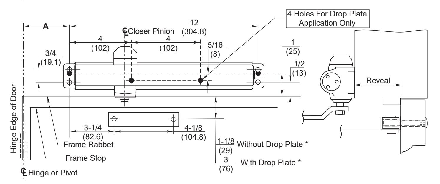
- * Always use frame or transom rabbet as reference plane, not bottom of stop.
- ** For 1-3/4" door with 4-1/2" wide butts or 3/4" offset-pivots, see Figure 2. For 1-3/4" door with center-pivots, see Figure 3. All other conditions require special template.
Do Not Scale Drawing
Left Hand Door Shown
Dimensions are in
| Arm | Non-Holder | J6600-4 | J6600-4 | J6600-4 | J620 | J6200-4 J6100-4 J | J640 | 0-4 | J6500-41 | J6400-42 | J6500-43 | |||||||||
|---|---|---|---|---|---|---|---|---|---|---|---|---|---|---|---|---|---|---|---|---|
|
Number
Stamp |
Hold-Open | J6200-7 | J6100-7 | J6400-7 | J6500-71 | J6400-72 | J6500-73 | |||||||||||||
| Reveal | inches | 0 - 3/8 | 1/2 - | · 2 | 2-1/2 - 3-1/4 3-3/8 - 4-1/4 | 4-3/8 - 5-3/8 | 5-1/2 - 6-3/8 | 6-1/2 - 7-3/8 | ||||||||||||
| Reveal | mm | 0 - 1 | 10 | 13 - | 50 | 55 - | 83 85 - 108 | 108 | 111 - 137 | 140 - 162 | 165 - 187 | |||||||||
| Door Op | ening Angle | Dimens | ion A | Dimens | ion A | Dimens | ion A | Dimens | ion A | Dimens | ion A | Dimension A | n A Dimension | |||||||
|
Hold
Open |
Door Stop | inches | mm | inches | mm | inches | mm | inches | mm | inches | mm | inches | mm | inches | mm | |||||
| 85° | 90° | 9-7/8 | 251 | 9-7/8 | 251 | 10 | 254 | 10 | 254 | 10-1/8 | 257 | 10-1/4 | 260 | 10-1/4 | 260 | |||||
| 90° | 95° | 9-1/4 | 235 | 9-1/4 | 235 | 9-3/8 | 238 | 9-3/8 | 238 | 9-1/2 | 241 | 9-5/8 | 244 | 9-5/8 | 244 | |||||
| 95° | 100° | 8-5/8 | 219 | 8-5/8 | 219 | 8-3/4 | 222 | 8-3/4 | 222 | 8-7/8 | 225 | 9 | 229 | 9 | 229 | |||||
| 100° | 105° | 8-1/8 | 206 | 8-1/8 | 206 | 8-1/4 | 210 | 8-1/4 | 210 | 8-3/8 | 213 | 8-1/2 | 216 | 8-1/2 | 216 | |||||
| 105° | 110° | 7-5/8 | 194 | 7-5/8 | 194 | 7-7/8 | 200 | 7-7/8 | 200 | 8 | 203 | 8-1/8 | 206 | 8-1/8 | 206 | |||||
| 110° | 115° | 7-1/4 | 184 | 7-1/4 | 184 | 7-1/2 | 191 | 7-1/2 | 191 | 7-3/4 | 197 | 7-7/8 | 200 | 7-7/8 | 200 | |||||
| Arm | Non-Holder | J6600-4 | J6600-4 | J6200-4 J6100-4 | J6400-4 | J6500-41 | J6400-42 | J6500-43 | |||||||||
|---|---|---|---|---|---|---|---|---|---|---|---|---|---|---|---|---|---|
|
Number
Stamp |
Hold-Open | J6200-7 | J6100-7 | J6400-7 | J6500-71 | J6400-72 | J6500-73 | ||||||||||
| Reveal | inches | 0 - 3 | 0 - 3/8 | 1/2 - 2 2-1/2 - 3-1/4 | 3-3/8 - | - 4-1/4 4-3/8 - 5-3/8 | 5-1/2 - 6-3/8 | 6-1/2 - 7-3/8 | |||||||||
| Reveal | mm | 0 - 10 | 13 - | 50 | 55 - | 55 - 83 85 - 108 | 111 - 137 | 140 - 162 | 165 - 187 | ||||||||
| Door Op | ening Angle | Dimens | ion A | Dimens | ion A | Dimens | ion A | Dimens | ion A | Dimens | ion A | A Dimension | Dimension A | ||||
|
Hold
Open |
Door Stop | inches | mm | inches | mm | inches | mm | inches | mm | inches | mm | inches | mm | inches | mm | ||
| 85° | 90° | 10-1/4 | 260 | 10-3/8 | 264 | 10-3/8 | 264 | 10-1/2 | 264 | 10-5/8 | 270 | 10-3/4 | 273 | 10-3/4 | 273 | ||
| 90° | 95° | 9-1/2 | 241 | 9-3/4 | 246 | 9-3/4 | 246 | 9-7/8 | 251 | 10 | 254 | 10-1/8 | 257 | 10-1/8 | 257 | ||
| 95° | 100° | 9 | 229 | 9-1/8 | 232 | 9-1/4 | 235 | 9-1/4 | 235 | 9-3/8 | 238 | 9-1/2 | 241 | 9-1/2 | 241 | ||
| 100° | 105° | 8-3/8 | 213 | 8-1/2 | 216 | 8-3/4 | 222 | 8-3/4 | 222 | 9 | 229 | 9-1/8 | 232 | 9-1/8 | 232 | ||
| 105° | 110° | 8 | 203 | 8-1/8 | 206 | 8-1/4 | 210 | 8-3/8 | 213 | 8-5/8 | 219 | 8-3/4 | 222 | 8-3/4 | 222 | ||
| 110° | 115° | 7-1/2 | 191 | 7-3/4 | 197 | 7-7/8 | 200 | 8 | 203 | 8-1/4 | 210 | 8-3/8 | 213 | 8-3/8 | 213 | ||
Installation Sequence
- Set average-power of multi-size closer. (Series UNI J8301, UNI J8501 ONLY) See Power Adjust chart on Page 1.
- See Figure 2 or 3 and select template dimensions. Note: Separate template required for other applications. Figure 2: 1-3/4" (44mm) thick door on 4- 1/2" (114mm) wide hinges or 3/4" (19mm) offsetpivots. Figure 3: 1-3/4" (44mm) thick door on centerpivots. Frame reveals and door opening angles as charted; shock absorber will permit five (5) degrees of door travel beyond hold-open position.
- Locate holes on frame face, stop-side. Four (4) for closer (or drop plate).
- Locate holes on door. Two (2) for arm-foot.
- Prepare door and frame for fasteners. See chart "Preparation for Fasteners" (Figure 4). Note: It is recommended to use sex-nuts to fasten arm foot to the door and to fasten the closer body to a flush transom.
- Mount drop plate, (if used) and closer. Closer power adjustment shaft toward lock edge.
- Disassemble rod-unit from arm-assembly and install on door. Rod under shock-absorber and closest possible to lock edge (See Figures 1 and 5).
- Mount main arm onto closer pinion shaft, aligning proper arm mark with pinion flat. Secure with main arm screw. Arm Mark "S" (See Figure 5).
- Insert connecting rod into slide unit and preload arm. Secure with rod screws. Adjust rod to perpendicular with door. See Figure 5.
- Adjust closer and install cover. See "Unit Adjustment" on back page.
|
Preparation for Fasteners
Figure 4 |
||||||||||
|---|---|---|---|---|---|---|---|---|---|---|
| Fasteners | Door or Frame | Drill-Sizes | ||||||||
| Self-Drilling Screw |
Aluminum
or Metal |
No drill required | ||||||||
| Standard | Wood | 3/16" (4.30 mm) | ||||||||
| 1/4" - 20 machine screw | Metal |
Drill: #7 (0.201" dia.)
Tap: 1/4" - 20 |
||||||||
| Sleeve nuts and bolts |
Hollow
Metal |
9/32" (7 mm) through;
3/8" (9.5 mm) door face opposite to closer |
||||||||
| Optional |
Aluminum
or Wood |
3/8" (9.5 mm) through | ||||||||
|
Through-bolts and
grommet-nuts |
All |
9/32" (7 mm);
3/8" (9.5 mm) dia. x 3/8" (9.5 mm) deep on door opposite to closer |
||||||||
Adjustment Instructions
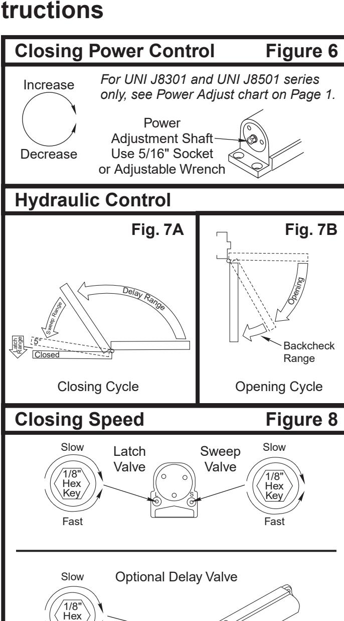
Closing Power See Figure 6
- ∞Adjust as required.
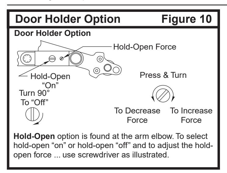
- ∞Hold-Open controls are at arm elbow (models suffixed "H"). To select hold-open on or hold-open off and to adjust the hold open force ... Use screwdriver as illustrated (See Figure 10).
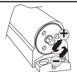
Closing Cycle (hydraulic control) See Figure 7A.
Valve "L" controls door speed in Latch range.
Valve "S" controls door speed in Sweep range .
Valve "D"—Optional—controls door speed in the Delay range . Use 1/8" hex-key furnished and adjust as shown in Figure 8.
Door closing time should be between 3 and 7 seconds from 90°. Longer closing time may be required for the elderly or handicapped.
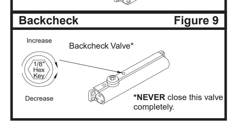
Opening Cycle (hydraulic control) See Figure 7B.
Valve "B" cushions (slows) door opening in the backcheck range.
Note: Never close this valve completely or damage to closer may occur.
Use 1/8" hex-key furnished and adjust as shown in Figure 9.
Installation of Cover:
- Full cover: Slide cover insert into the un-used cutout in cover. Install cover using screws provided.
- Narrow cover: Install cover using screws provided. Screw pinion cap onto shaft by hand or with a phillips screwdriver DO NOT OVERTIGHTEN.
- ∞Full metal cover: Fasten cover to mounting clips with screws provided.
- ∞Architectural plastic cover: Slide cover insert into the unused cutout in cover. Install standoffs in ends of closer. Snap cover onto standoffs.
- ∞Architectural metal cover: Remove cover insert where pinion is located. Install standoffs in ends of closer. Install cover using screws provided.
Copyright © 2005, 2008, 2024, ASSA ABLOY Accessories and Door Controls Group, Inc. All rights reserved. Reproduction in whole or in part without the express written permission of ASSA ABLOY Accessories and Door Controls Group, Inc. is prohibited.

ASSA ABLOY, the global leader in door opening solutions 3000 Highway 74 East • Monroe, NC 28112 Tel: (877)-974-2255 • Fax: (800)-338-0965 www.nortondoorcontrols.com