Norton Rixson 8000 Series Door Closer Regular, Top Jamb, or Parallel Arms Non-Hold Open Installation Instruction…_80-9380-2206-020
Open the original PDF document
View PDF8000 Series Door Closer
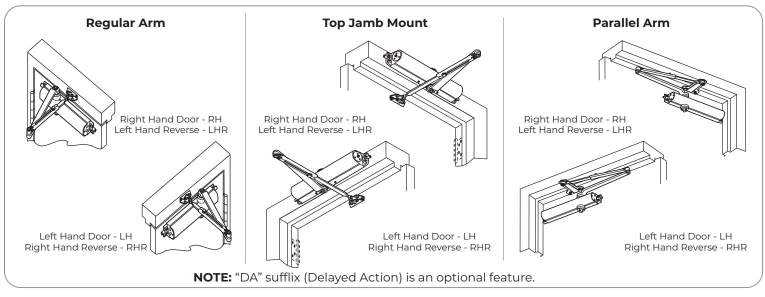
Regular, Top Jamb, or Parallel Arms Non-Hold Open Installation Instructions


This product can expose you to lead which is known to the state of California to cause cancer and birth defects or other reproductive harm. For more information go to: www.P65warnings.ca.gov.
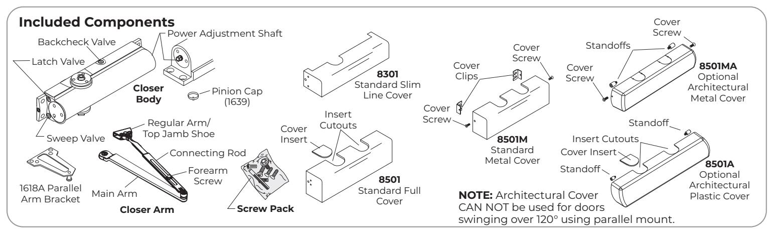
Non-Hold Open Arm Models 8101, 8301, 8501
READ AND FOLLOW ALL INSTRUCTIONS. SAVE THESE INSTRUCTIONS.
property damage or personal injury. These instructions should be followed to avoid the possibility of
An incorrectly installed or improperly adjusted door closer can cause CAUTION misapplication or misadjustment.

8000 Series Non-Hold Open Closer
NOTES: For special applications a separate door and frame preparation template is packed with these instructions. Use this instruction sheet for installation sequence and closer adjustments only.
- Doors should be hung on ball bearing or anti-friction hinges.
- A separate door stop is recommended.
- Door and frame must be properly reinforced.
- Always adjust spring power before adjusting control.
- Adjust closing time speed between 3 and 7 seconds from 90° to 0°. Greater closing times may be required for elderly or handicapped.
- These door closers should NOT be installed on the exposed side (weather side) of exterior doors.
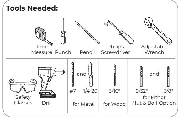
Supplied Hardware
| Mounting Hardware | Door or Frame | Drill | |||
|---|---|---|---|---|---|
| Closer, PA Bracket: 1/4-14 x 1-1/2 Oval Flat Head Self Drilling Screw | 3/16" (4.8mm) for wood | ||||
|
Closer, PA Bracket:
1/4-20 x 3/4 Oval Flat Head Mach. Screw |
Motol |
Drill #7 (.201 dia. or 5.1mm)
Tap 1/4-20 |
|||
| ()WMWW |
Arm Shoe to Jamb or Door:
1/4-20 x 5/8 Round Head Mach. Screw |
Metal | |||
|
Arm Shoe to Jamb or Door:
1/4-14 x 1-1/2 Round Head Self Drilling Screw |
3/16" (4.8mm) for wood | ||||
| Closer: Sleeve Nut and Bolt (SNB) (optional) | Hollow Metal |
9/32" (7.0mm) thru
3/8" (9.5mm) door face opposite to closer |
|||
|
with 1/4-20 x 3/4 Oval Flat Head Mach. Screw
(recommended) |
Aluminum or Wood | 3/8" (9.5mm) thru | |||
| Decemberations |
Closer:
Thru Bolt and Grommet Nut (TBGN) (optional) |
All |
9/32" (7.0mm) thru
3/8" (9.5mm) dia. x 3/8" (9.5mm) deep, door face opposite to closer |
||
Closer Adjustments

By law the Americans with Disabilities Act (ADA) may require that door closer installation comply with accessibility guidelines.

The closing force for series 8301 & 8501 door closers is adjustable from a size 1 to a size 6, as outlined in ANSI Standard A156.4. When these series of door closers are installed and adjusted to conform to ADA reduced opening force requirements (5 lbs max.) for interior doors, they may not have adequate closing force to reliably close and latch the door. Power adjustments charted on this page are recommended where possible, to ensure proper door control.
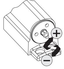
| Spring Power Adjustment | ||||
|---|---|---|---|---|
| Use 5/16" socket or adjustable | ||||
| wrench for this adjustment) | ||||
| Spring Closing Power | Number of Turns Required | ||||||
|---|---|---|---|---|---|---|---|
| | | |
Type of
Installation |
Maximum Door Size | |||||
| Door | * |
34"
(86cm) |
36"
(91cm) |
40"
(102cm) |
48"
(122cm) |
||
| 8101/8301/8501 | Interior |
Regular Arm
Top Jamb |
Full 360° Turns | 5 | 8 | 11 | 13 |
| Parallel Arm | 7 | 10 | 13 | 16 | |||
| Exterior |
Regular Arm
Top Jamb |
7 | 10 | 13 | 16 | ||
| Parallel Arm | 9 | 12 | 15 | 18 | |||
Number of Turns Dequired
Closer is shipped set at mid range setting = 10 turns
*20 Full (360°) turns maximum available.
Spring Closing Dower

Adjust Closing Speed Time to between 3 to 7 seconds from . Use of the door by handicapped, elderly or small children may require greater closing time.
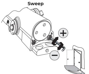
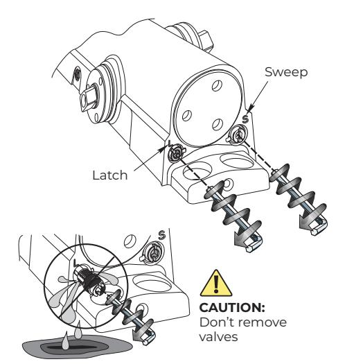
Caution: Don't completely close valve

8000 Regular Arm Installation (Right Hand Shown)
A. Prepare door and frame.
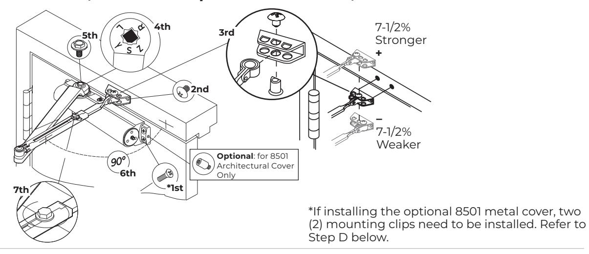
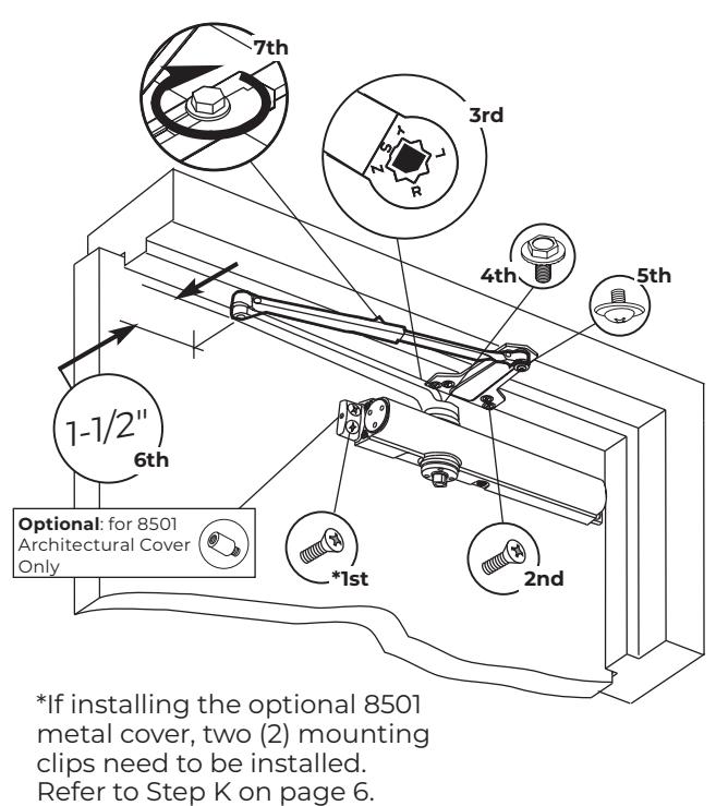
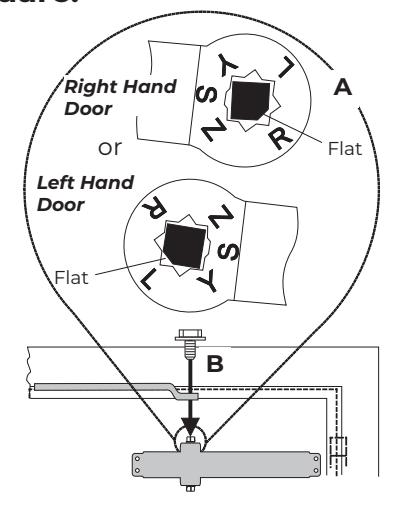
B. Install Closer to Door, Choose arm placement in shoe, and install arms.
C. Adjust closer.
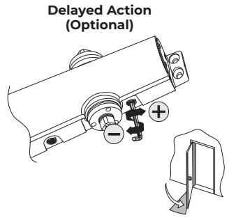
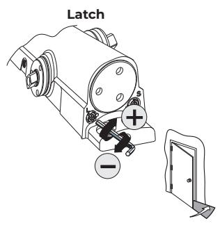
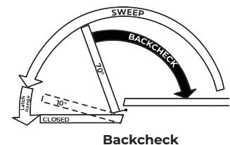
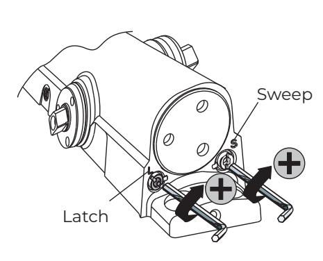
Refer to page 2 for Delayed Action, Sweep, Latch, and Backcheck closer adjustments.
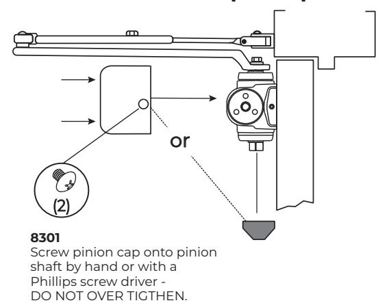
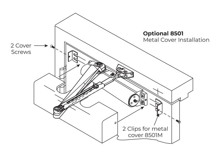
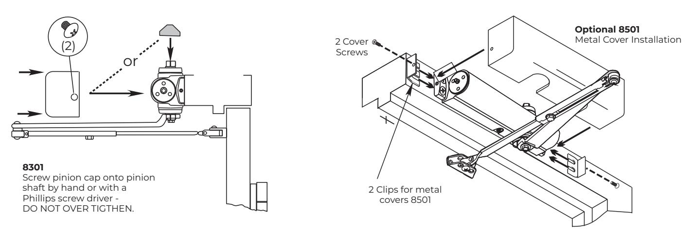
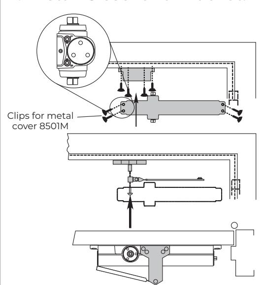
D. Install Pinion Cap or Optional Cover
The 8000 Non-Hold Open Closer - Regular Arm has now been installed.

8000 Top Jamb Installation (Right Hand Shown)
A. Prepare door and frame.
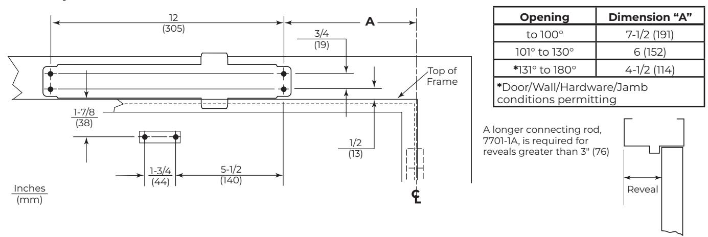
B. Install Closer to Door, Choose arm placement in shoe, and install arms.
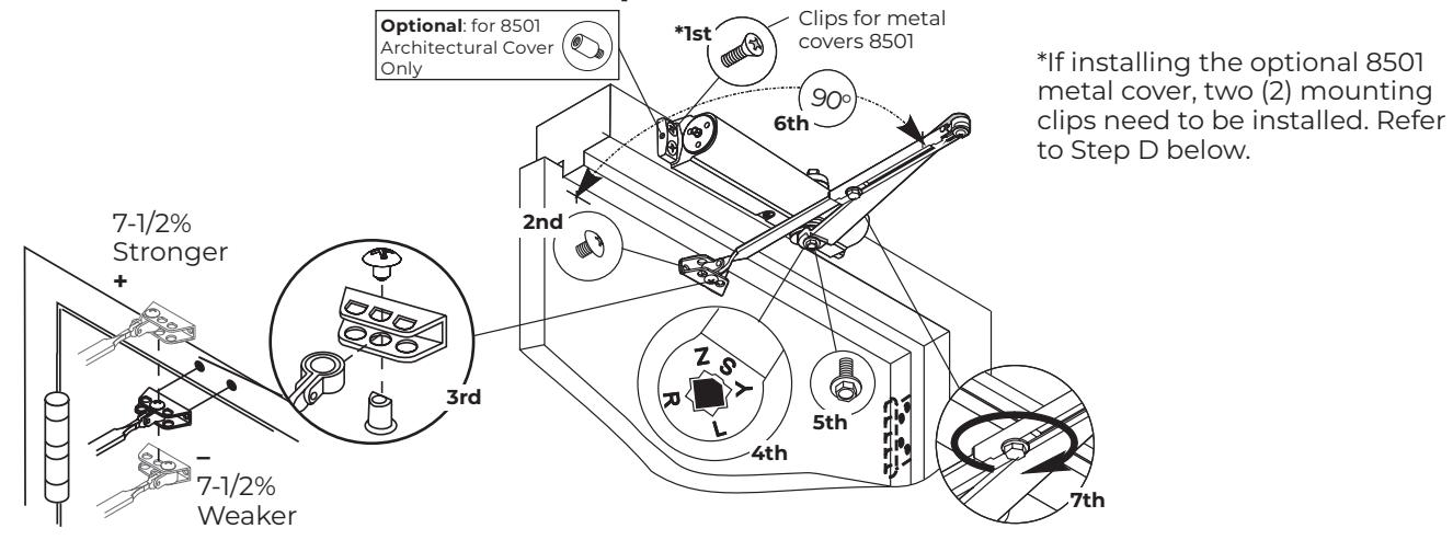
C. Adjust closer.
Refer to page 2 for Delayed Action, Sweep, Latch, and Backcheck closer adjustments.
D. Install Pinion Cap or Optional Cover
The 8000 Non-Hold Open Closer - Top Jamb has now been installed.

8000 Parallel Arm Installation (Right Hand Shown)
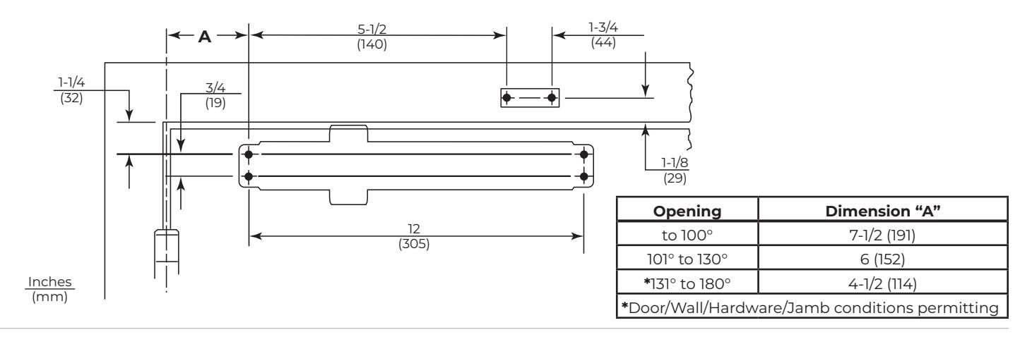
A. Prepare door and frame.
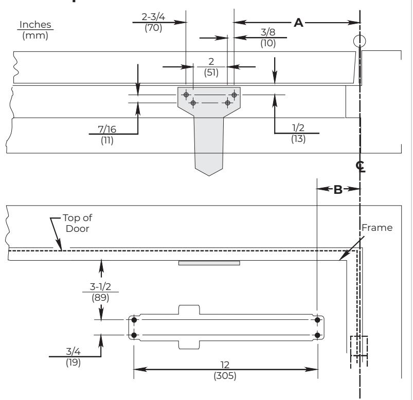
| Opening | A | B | |
|---|---|---|---|
| to 120° | 9-1/2 (241) | 3-3/4 (95) | |
| *121° to 180° | 7 (178) | 1-1/4 (32) | |
* Door/Wall/Hardware/Jamb conditions permitting. 8501A and 8501MA Series cannot be installed for this door opening range.
B. Install Closer to Door, Choose arm placement in shoe, and install arms.
C. Close Valves. D. Install Closer and Bracket. E. Preload Closer.
Continued on next page...

8000 Parallel Arm Installation (Right Hand Shown)-cont.
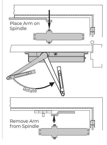
F. Install arms on Pinion Square.
G. Open Valves. H. Assemble Arm.
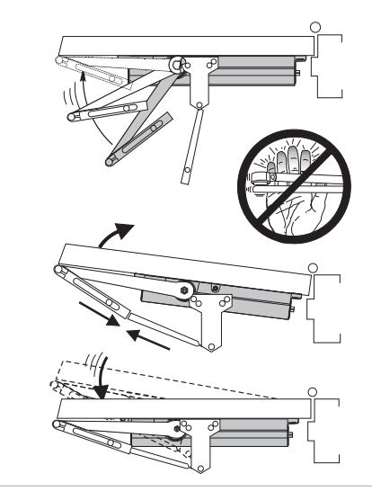
I. Install Arm Screw.
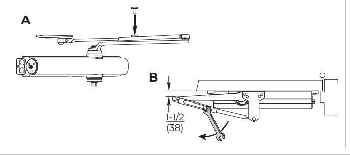
J. Adjust closer.
Refer to page 2 for Delayed Action, Sweep, Latch, and Backcheck closer adjustments.
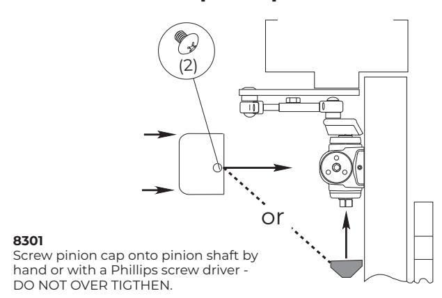
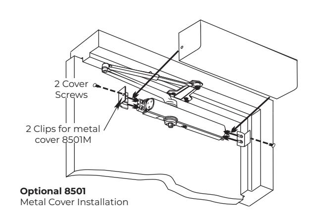
K. Install Pinion Cap or Optional Cover
The 8000 Non-Hold Open Closer - Parallel Arm has now been installed.
Technical Product Support: Monroe, NC 28112 USA Phone: 877.974.2255 ext: 2
Techsupport.NortonRixson@assaabloy.com
NortonRixson.com