Norton Rixson 8000 Series Door Closer, R8000, Regular Rigid Arm, Non-Hold Open Installation Instructions_80-9380-2215-020
Open the original PDF document
View PDF8000 Rigid Regular Arm Door Closer
Non Hold Open Pull Side Installation Instructions


/ WARNING
This product can expose you to lead which is known to the state of California to cause cancer and birth defects or other reproductive harm. For more information go to: www.P65warnings.ca.gov.
NOTE: For Special Applications a separate door and frame preparation template is packed with these instructions. Use this instruction sheet for installation sequence and closer adjustments only.
An incorrectly installed or improperly adjusted door closer can cause property damage or personal injury. These instructions should be followed to avoid the possibility of misapplication or misadjustment

The closing force for series 8000ST door closers is adjustable from a size 1 to a size 6, as outlined in ANSI Standard A156.4. When these series of door closers are installed and adjusted to conform to ADA reduced opening force requirements (5 lbs max.) for interior doors, they may not have adequate closing force to reliably close and latch the door. Power adjustments charted on page 4 are recommended where possible, to ensure proper door control.
READ AND FOLLOW ALL INSTRUCTIONS.
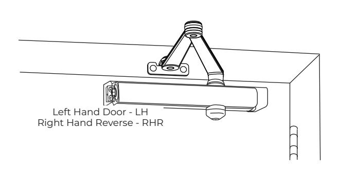
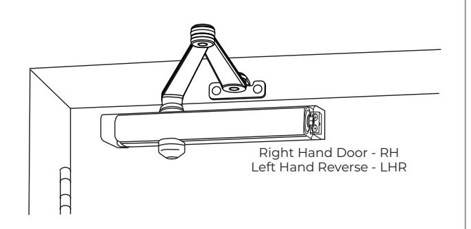
Pull Side Installation
Closer mounts on hinge (pull) side of door. Models shown with narrow cover installed.
| Closer Power† | Series | |||
|---|---|---|---|---|
| Multi-Size Closer 1 |
R8301
(Slim Line Cover) |
R8501
(Full Cover) |
||
This series of door closers is not available with a hold open function.
With or without "DA" suffix (delayed action).
- <sup>1</sup> Series can be adjust from power size 1 thru 6
- † Size 1 = weakest power, size 6 = strongest.
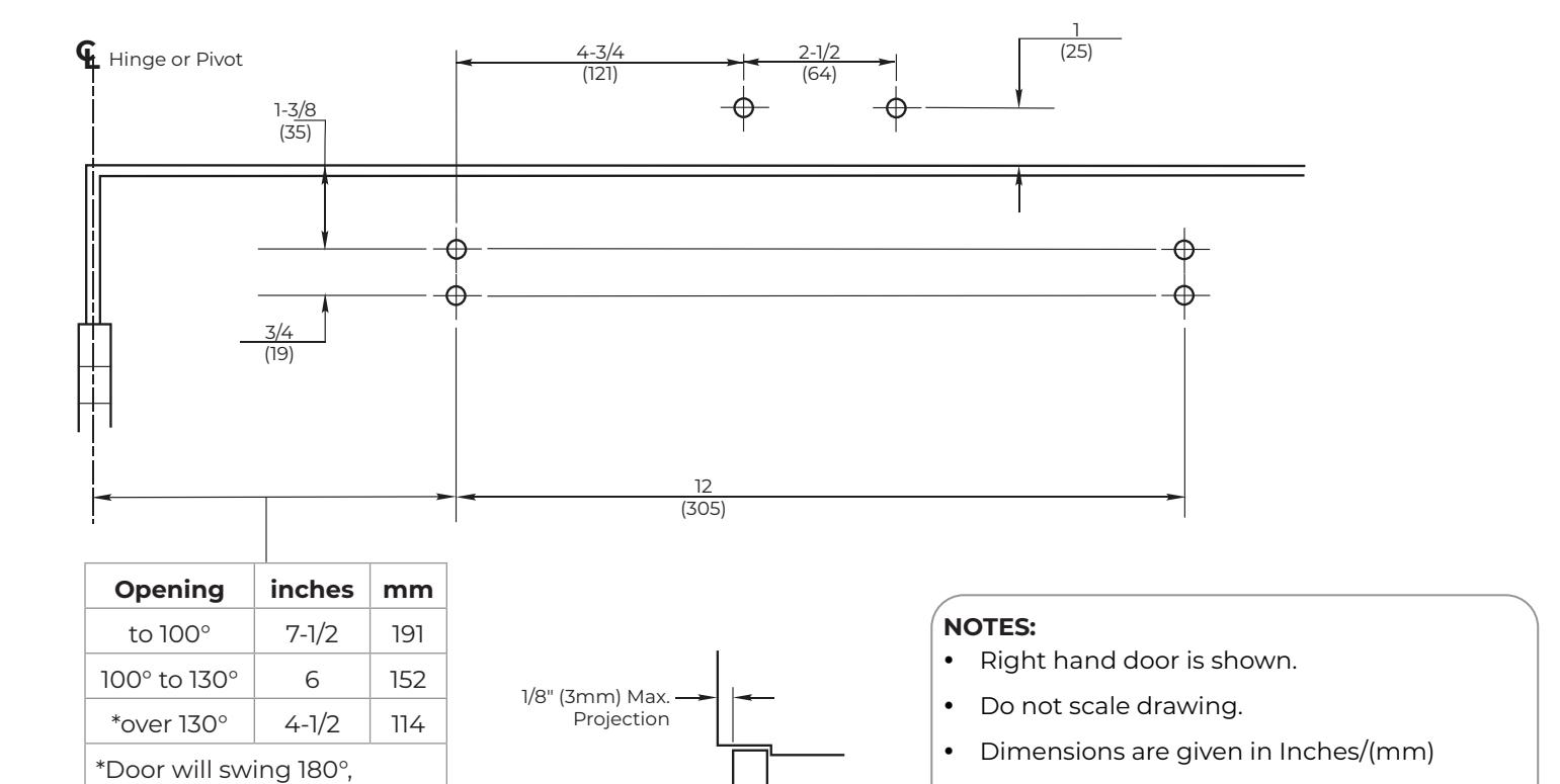
- MAXIMUM HINGE SIDE FRAME REVEAL IS 1/8" (3mm).
- All components are non handed.
- It is recommended that the door, on which the door closer will be installed, be hung on ball bearing hinges. Door must swing freely.
- A separate door stop, supplied by others, is recommended to prevent damage to the door closer, closer arm, or to the door, frame or adjacent walls.
- Door and Frame must be properly reinforced, or use of special fasteners employed, to prevent the mounting screws from pulling out.
- All dimensions are given in inches with corresponding metric dimensions (millimeters) in parenthesis.
- Door closer cover projects 2-1/8" (54 mm) from door surface.

R8000 Series Rigid Regular Arm Door Closer
Pull Side Installation
conditions permitting.
| Preparation for Fasteners | |||||
|---|---|---|---|---|---|
| Fasteners |
Door or
Frame |
Drill-Sizes | |||
| Self-Drilling Screw |
Aluminum
or Metal |
3/16" (4.30mm) | |||
| Wood | 3/16" (4.30mm) | ||||
| 1/4"-20 Machine Screw | Metal |
#7 (0.201" dia) or 5 (10mm)
Tap: 1/4"-20 |
|||
|
Sleeve nuts and bolts
(optional) |
Hollow
Metal |
9/32" (7mm) through;
3/8" (9.5mm) door face opposite of closer |
|||
|
Aluminum
or Wood |
3/8" (9.5mm) through | ||||
|
Through-bolts and
grommet-nuts (optional) |
All |
9/32" (7mm);
3/8" (9.5mm) dia. x 3.8" (9.5mm) deep on door face opposite of closer |
|||
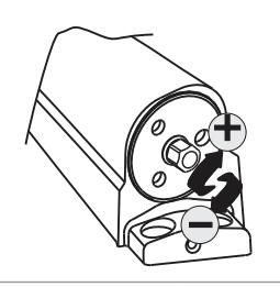
Power Adjust
Use 5/16" Socket or Adjustable Wrench for this adjustment.
80-9380-2215-020 Rev 3 06/23
| Power Adjustment Chart | ||||||
|---|---|---|---|---|---|---|
| Number of Turns Required | ||||||
| DOOR | MAXIMUM DOOR SIZE | |||||
|
32"
(81cm) |
36"
(91cm) |
42"
(107cm) |
48"
(122cm) |
|||
| Interior Door | 0 | 2 | 5 | 8 | ||
| Exterior Door | 2 | 5 | 8 | 11 | ||
y Same dimensions apply for Left Hand Door measured from centerline of pivot point.
NOTE: Maximum of 20 turns (360°) of Power Adjust Shaft. Closer is shipped set at 10 turns.
R8000 Series Rigid Regular Arm Door Closer

Installation Instruction
- 1. Select angle of opening and use dimensions shown to locate four (4) holes on door for closer body and 2 holes on frame face for arm shoe.
- 2. Prepare door and frame for fasteners. See "Preparation for Fasteners" on page 2.
- 3. Set closing power for door size using chart on page 2.
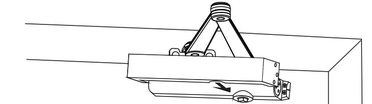
- 4. Mount closer body on door. Be sure that power adjustment shaft is away from hinge.
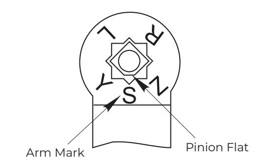
- 5. Place main arm on shaft, aligning 'S' mark on arm with pinion flat on pinion shaft (see illustration at right). Push down into position. Secure with 1/4-20 x1/2 (13) 7/16" hex washer head screw.
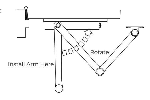
- 6. With door closed, rotate main arm away from hinge and align shoe with mounting holes in frame. Fasten arm shoe to frame with round head screws provided.
CAUTION : Closer arm is under spring tension and may be difficult to rotate.
- 7. Make closer adjustments (see page 4) before installing cover. CAUTION : Do Not Back Valves Out of Closer or a Leak Will Result.
-
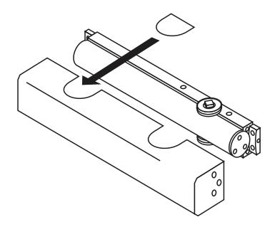
8. Install cover.
- ‒ R8300 Series Only :
Fasten cover to closer with 2 #6-32 x 5/16 FHMS screws. Screw Pinion cap onto pinion shaft by hand or with a Phillips screw driver - DO NOT OVER TIGHTEN
‒ R8500 Series Only :
Place insert into notch in cover that will not be used. Fasten cove to closer with 2 #6-32 x 5/16" FHMS screws at each end of closer.

The ASSA ABLOY Group is the global leader in access solutions. Every day we help people feel safe, secure and experience a more open world.

ASSA ABLOY
Closer Adjustments
Closing Power Adjustment -
Using "Power Adjustment Chart" on page 2, select the correct number of turns for power adjustment shaft that corresponds with the installation. With 5/16" socket or adjustable wrench, rotate adjustment full 360° clockwise turns to desired setting. After closer has been installed and proper adjustments made to the sweep and latch, it may be necessary to readjust spring power for good closing action.
Control Valve Adjustments (see Figure 2)
Closing Speed Controls (Figure 1A or 1B and 2)
- Valve "S" Controls Sweep Range
- Valve "L" Controls Latch Range
- Valve "D" Controls Delay Range For optional Delayed Action models
Opening Cycle
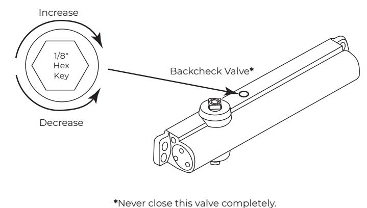
"Backcheck" valve controls the strength of cushioning in Backcheck Range. NEVER close this valve completely – it is not to provide a positive stop. (see Figure 4 and Figure 5)
Figure 1 - Closing Speed Controls
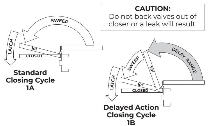
Figure 2 - Closing Speed Controls
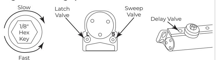
Figure 3 - Closing Power Control
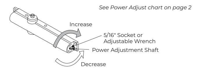
Figure 4 - Opening Door Control
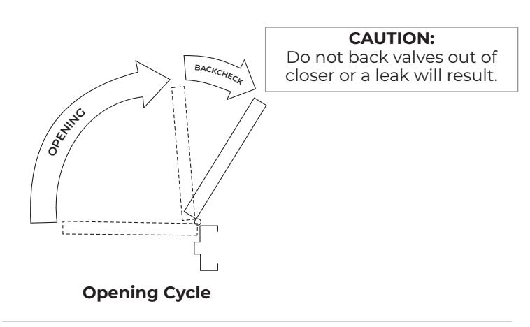
Figure 5 - Backcheck Control
Technical Product Support: Monroe, NC 28112 USA
Phone: 877.974.2255 ext: 2
Techsupport.NortonRixson@assaabloy.com
NortonRixson.com