Norton Rixson 8000 Series Door Closer, 8341ST & 8541ST Door Closers, Push or Pull, Non-Hold Open or Hold Open In…_80-9380-2212-020
Open the original PDF document
View PDF8040ST - 8050ST Slide Track Door Closer
Pull or Push Side
Installation Instructions
With or without DA suffix (Delayed Action) With or without M suffix (Metal cover)


This product can expose you to lead which is known to the state of California to cause cancer and birth defects or other reproductive harm. For more information go to: www. P65warnings.ca.gov.
Non Hold open Arm Models: 8341ST - 8541ST Series PS8341ST - PS8541ST
Hold open Arm Models: 8341ST-H - 8541ST-H Series PS8341ST-H - PS8541ST-H
Adjustable Power size 1-6
READ AND FOLLOW ALL INSTRUCTIONS. SAVE THESE INSTRUCTIONS.
An incorrectly installed or improperly adjusted door closer can cause property damage or personal injury. These instructions should be followed to avoid the possibility of misapplication or misadjustment.
CAUTION
Installation Type
For use on doors with 4 1/2" or 5" (115-127mm) Wide Butt Hinges
Pull (Hinge) Side Mounted Refer to page 3
Push (Stop) Side Mounted Refer to page 4
8050 Series Hold Open Units Are Not Permitted To Be Installed In Fire Door Assemblies
- Maximum pull side frame reveal is 1/8" (3mm).
- Minimum frame face for pull side is 1-3/8" (35 mm).
- All components are non handed.
- The use of ball bearing hinges is recommended for the door on which the closer will be installed.
- · Door must swing freely.
- Where severe or abusive conditions are expected a separate door stop, supplied by others, is recommended to assist in preventing damage to the door closer, closer arm; or to the door, frame or adjacent walls.
- Door and frame must be properly reinforced, or the use of special fasteners employed, to prevent door collapse or the mounting screws from pulling out.
- All dimensions are given in inches with corresponding metric dimensions (millimeters) in parentheses.

ASSA ABLOY
8040ST - 8050ST Series Side Track Door Closer
Installation Sequence (Pull or Push Side Mount)
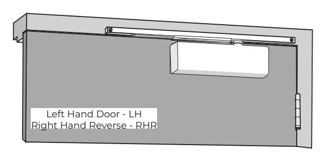
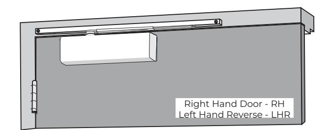
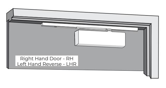
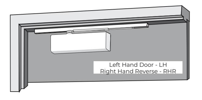
1. Determine hand of door
Using the illustrations on page 1, determine the hand of door and type of installation.
2. Use template dimensions to locate fastener holes on door and frame . Refer to pages 3 and 4 to locate fastener holes on door and frame. Refer to "Preparation for Fasteners" chart for fastener information.
Frame : Prepare the frame for mounting track. Drill and tap holes for 1/4-20 machine screws or #14 wood screws.
Door : Prepare the door for mounting closer. Drill and tap (4) holes for 1/4-20 machine screws, #14 wood screws, 3/8 diameter sex-nuts, or through bolts and grommet-nuts.
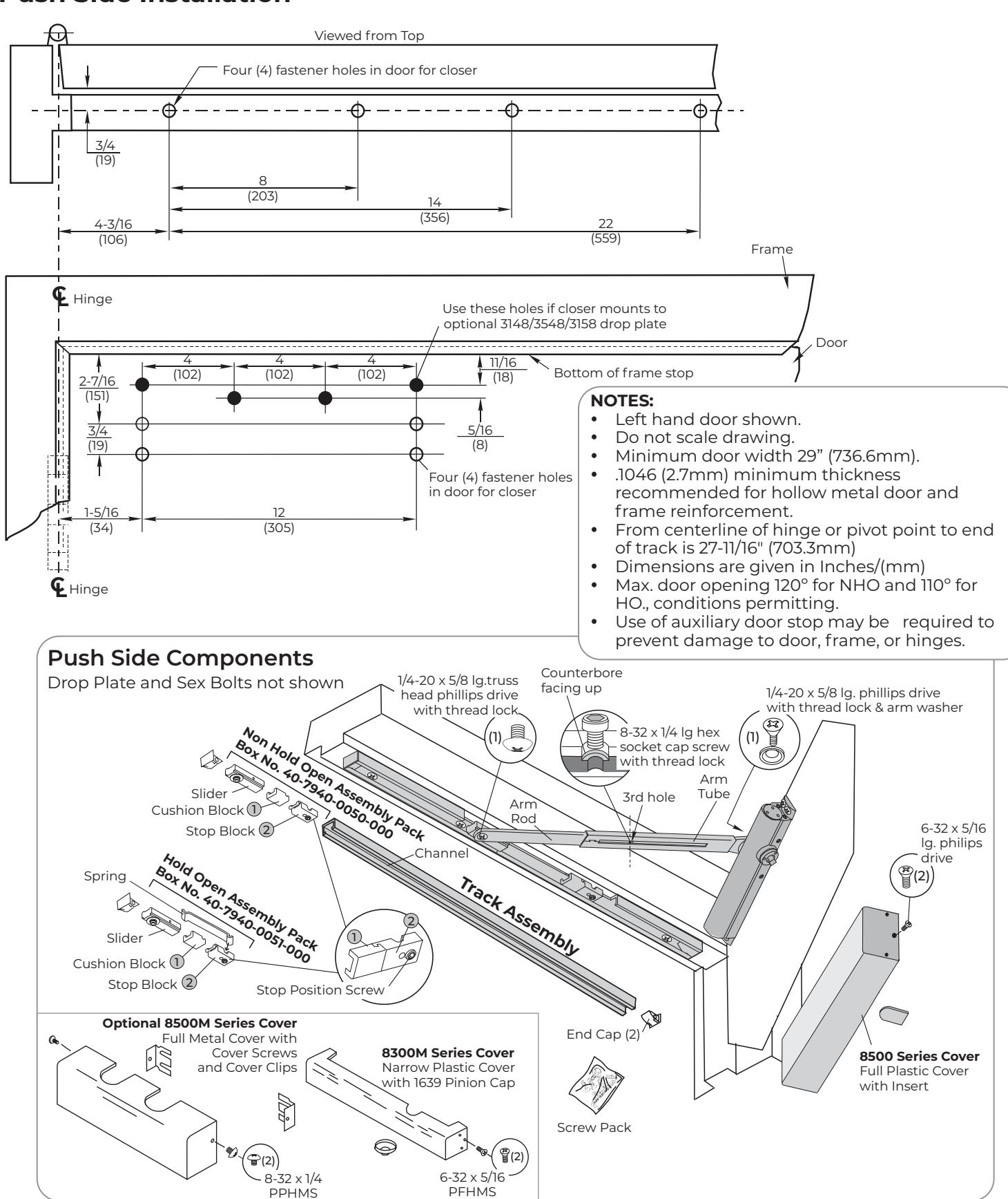
NOTE: If drop plate is used (see page 4), prepare holes for 8148/8548/8158 drop plate instead of closer. Secure drop plate before mounting closer.
3. Fasten closer to door or drop plate.
Position closer with:
Pull side : Power adjustment shaft away from hinge Push side : Power adjustment shaft toward hinge Secure mounting screws.
NOTE: If using full metal cover, mounting clips must be slipped under ends of closer when closer is being mounted. Clips should project 1/4" (6 mm) from each end of closer.
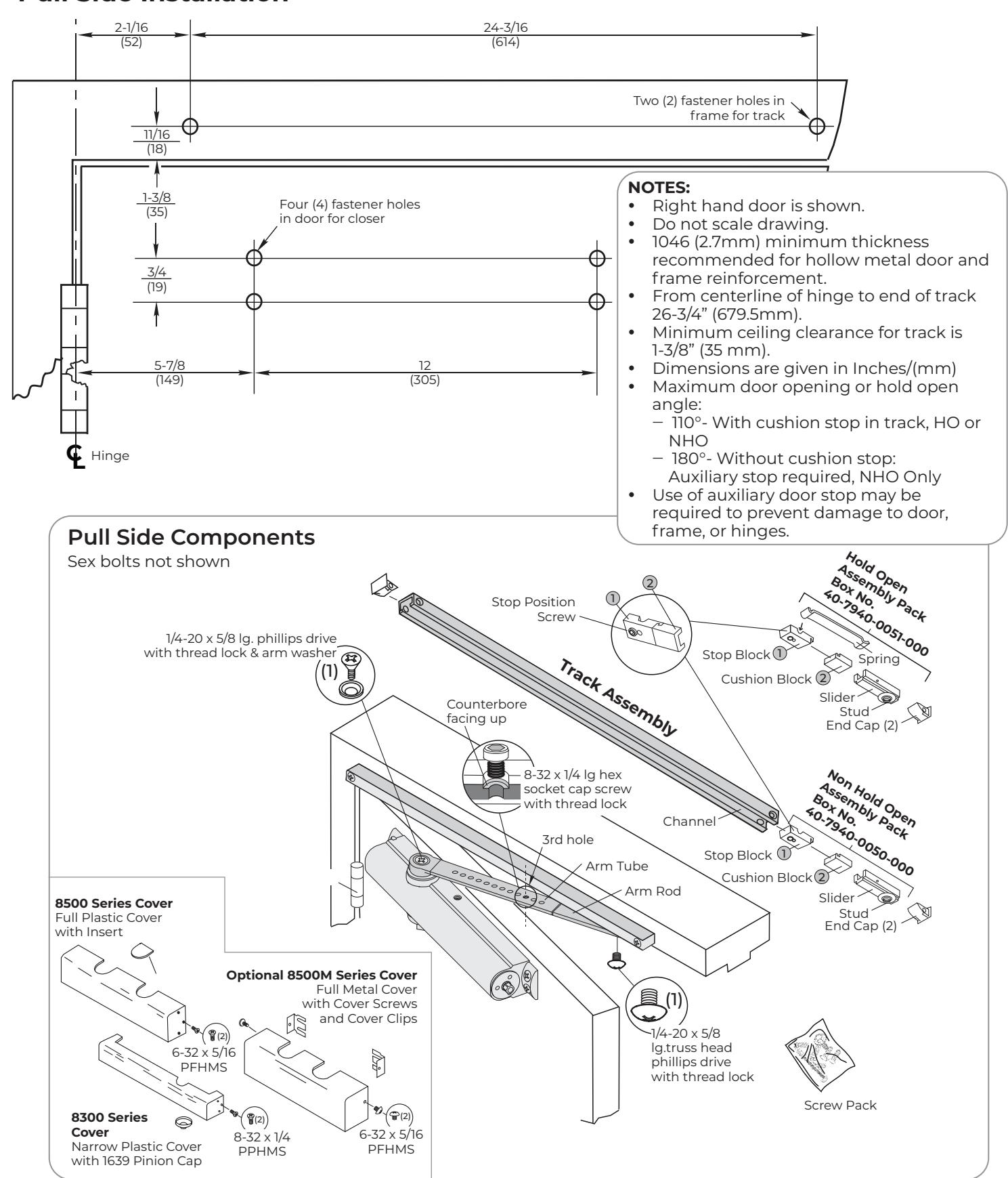
4. Assemble Slide Arm . Insert flat arm rod into arm tube with the counterbore screw hole facing up. Align counterbore with the 3rd hole in the arm tube and secure with 8-32 x 1/4 long hex socket cap screw. See illustration on pages 3 or 4.
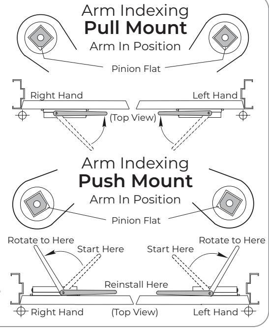
5. Install arm on closer pinion.
Refer to arm indexing illustrations below:
Pull mount:
Position slide arm with counterbore facing up and align with pinion flat as illustrated. Install onto pinion.
Push mount:
With "S" & "L" valves closed, place arm on closer pinion shaft with arm at a 45° angle to frame face. Rotate arm toward hinge at least 50°.Remove arm and reinstall on pinion with arm almost parallel to frame face, before pinion shaft can rotate far enough to create interference with door.
6. Secure arm.
Secure arm with washer and flat head phillips drive arm screw with thread lock.
| Preparation for Fasteners | |||
|---|---|---|---|
| Fasteners |
Door or
Frame |
Drill-Sizes | |
|
#14 type A
S,M, screw Closer: 1-1/4" (32mm) Track: 2-3/4" (70mm) |
Wood | 7/32" (5.56mm) | |
|
1/4"-20 Machine
Screw |
Metal |
Drill: #7 (0.201" dia)
Tap: 1/4"-20 |
|
| Sex nuts and bolts |
Hollow
Metal |
9/32" (7mm) through;
3/8" (9.5mm) door face opposite of closer |
|
|
Aluminum
or Wood |
3/8" (9.5mm) through | ||
| Through-bolts and grommet-nuts (optional) | All |
9/32" (7mm);
3/8" (9.5mm) dia. x 3.8" (9.5mm) deep on door face opposite of closer |
|
7. Assemble Track.
Remove slider assembly parts from box # 40-7940-0050-000 for Non Hold Open or # 40-7940-0051-000 for Hold Open and insert into channel in the order shown. See illustration on pages 3 or 4. Insert end caps into ends of track prior to installing.
NOTE: Use of the hold open assembly pack on a non hold open device will void the UL® listing for this product.
8. Install track to frame.
Place the assembled slide track against frame with the open side down, stop and cushion blocks toward the hinge. Move the slider to the opposite end of the slide track. Secure slide track with 1/4-20 flat head phillips drive mounting screws.
9. Connect arm to track.
Pull side: With door closed.
Push side : With door open slightly. Rotate arm to slider and place end over stud. Push up on arm and tap gently to seat (to prevent stud from turning during assembly). Secure with 1/4-20 x 5/8" long truss (rounded) head phillips drive screw with thread lock. CAUTION : Closer arm is under spring tension and may be difficult to rotate.
10. Set door stop angle.
Open door to the angle you want the door to stop. With the door held at that location, slide stop with cushion block against slider. Tighten the stop position screw (large set screw) with 3/16" hex wrench (from screw pack) until secure. Release door.
- 11. Adjust closer (see page 5) before installing cover.
- 12. Install Cover.
Full Cover : Slide insert into unused cover slot (see illustration on pages 3 or 4). Install cover using screws provided.
Narrow Cover : Install cover using screws provided. Thread pinion cap into pinion shaft.
Do not overtighten.
Full Metal Cover : Fasten cover to mounting clips with screws provided.
Experience a safer and more open world
8040ST - 8050ST Series Side Track Door Closer

Pull Side Installation

8040ST - 8050ST Series Side Track Door Closer
Push Side Installation

Closer Adjustments
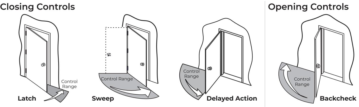
Closing Power
For proper sizing see power adjustment chart below right. To adjust closer power, see Figure 1 . Increase or decrease power as necessary.
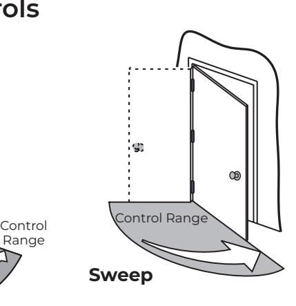
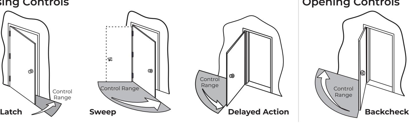
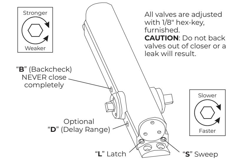
Closing Cycle (see illustrations above) .
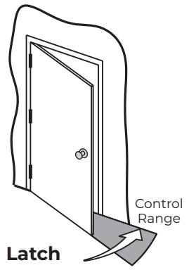
- ‒ Valve " L " controls door speed in Latch Range.
- ‒ Valve " S " controls door speed in Sweep Range.
- ‒ Valve " D " (Optional) controls door speed in Delay Range.
Use 1/8" hex-key furnished and adjust as shown in Figure 2 .
NOTE: Adjust closing speed to between 4 to 7 seconds from 90°. Use of door by handicapped, elderly or small children may require greater closing time.
Opening Cycle (see illustration above).
‒ Valve " B " cushions (slows) door opening in the Backcheck Range.
NOTE: Never close this valve completely or damage to closer may occur.
Figure 1 - Closing Power Controls
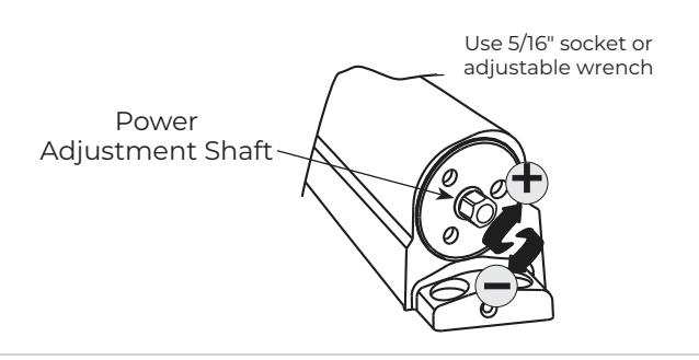
Figure 2 - Closing Speed Controls
| Power Adjustment Chart NOTE: | ||||
|---|---|---|---|---|
|
DOOR
SIZE inches |
Full Clockwise Turns
of Closer Power Adjustment Shaft |
Power adjustments charted are
recommended where possible to ensure proper door control. See Note on page 1 |
||
| (cm) | INTERIOR EXTERIOR |
where codes may dictate reducing these
recommended adjustments. Maximum of 20 turns (360°) of Power |
||
|
28-32
(71-81) |
10 | 13 | ||
|
33-36
(84-91) |
12 | 15 |
Adjustment Shaft.
Set closing power, as charted. Closer is shipped at power setting as circled. See |
|
|
37-42
(94-107) |
14 | 17 | ||
|
43-48
(109-122) |
17 | 19 |
Figure 1 at left for illustration of how to make
these adjustments. |
|
Technical Product Support: Monroe, NC 28112 USA Phone: 877.974.2255 ext: 2
Techsupport.NortonRixson@assaabloy.com
NortonRixson.com