Norton Rixson 8000 Series Door Closer, 8080, Low Profile Arm, Non-Hold Open Installation Instructions_80-9380-2210-020
Open the original PDF document
View PDF8080 Series Door Closer
Non Hold Open Low Profile Arm
Installation Instructions
8381/8581 Series, adjustable size 1 through 6.


WARNING
SAVE THESE INSTRUCTIONS. This product can expose you to lead which is known to the state of California to cause cancer and birth defects or other reproductive harm. For more information go to: www.P65warnings.ca.gov.
CAUTION
CAUTION An incorrectly installed or improperly adjusted door closer can cause property damage or personal injury. These instructions should be followed to avoid the possibility of misapplication or misadjustment.
NOTES :
– For Special Applications a separate door and frame preparation template is packed with these instructions. Use this instruction sheet for installation sequence and closer adjustments only. – "DA" Suffix - Delayed Action closing is an optional feature.
READ AND FOLLOW ALL INSTRUCTIONS.
The closing force for series 8381 & 8581 door closers is adjustable from a size 1 to a size 6, as outlined in ANSI Standard A156.4. When these series of door closers are installed and adjusted to conform to ADA reduced opening force requirements (5 lbs max.) for interior doors, they may not have adequate closing force to reliably close and latch the door. Power adjustments charted on page 4 are recommended where possible, to ensure proper door control.
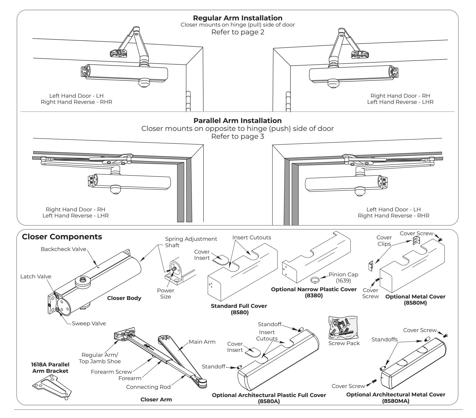
8080 Series Non-Hold Open Closer
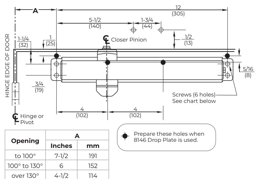
Regular Arm Installation (Right Hand Shown)
Installation Sequence
-
y Select door opening angle. Using template dimensions:
- ‒ mark 4 holes on door for closer or 4 holes ( ) for 8146 Drop Plate
- ‒ mark 2 holes on frame for arm shoe.
- y Prepare for fasteners See "Preparation for Fasteners" on this page.
- y Remove forearm screw from arm assembly and fasten the arm shoe assembly to the frame face. (Slot facing down.)
- y Mount closer body to door. Place end with 2 regulating valves toward hinge edge of the door.
NOTE: If using full metal cover, the cover mounting clips must be slipped under the ends of the closer while the closer is being mounted.
- y Install main arm on top of pinion shaft. Align the pinion flat with the letter " S ". (See Figure 1) Fasten with arm screw.
- y Reassemble Arm. Adjust forearm perpendicular to door (90° angle). Install and tighten set screw. See illustration below template.
- y Adjust closer. Refer to page 4.
- y Install Pinion Cap and/or Cover. Refer to page 4.
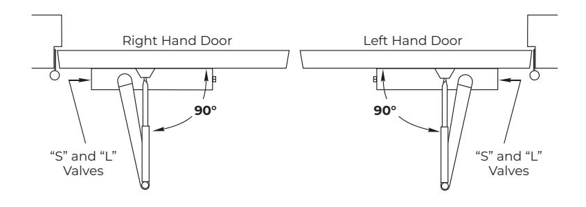
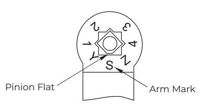
Figure 1
| Preparation for Fasteners | ||||||||
|---|---|---|---|---|---|---|---|---|
| Fasteners | Door or Frame | Drill-Sizes | ||||||
| Standard | Self-Drilling |
Aluminum or
Metal |
No drill required | |||||
| Screw | Wood | 3/16" (4.30mm) | ||||||
|
1/4"-20
Machine Screw |
Metal | Drill: #7 (0.201" dia) | ||||||
| Optional |
Sleeve nuts
and bolts |
Hollow Metal |
9/32" (7mm) through;
3/8" (9.5mm) door face opposite of closer |
|||||
|
Aluminum or
Wood |
3/8" (9.5mm) through | |||||||
|
Through-bolts
and grommet-nuts |
All |
9/32" (7mm);
3/8" (9.5mm) dia. x 3.8" (9.5mm) deep on door face opposite of closer |
||||||

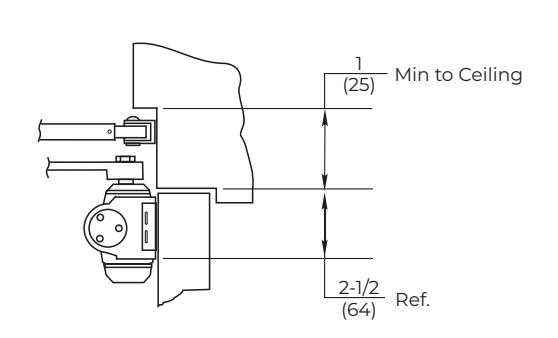
Parallel Arm Installation (Left Hand Shown)
Installation Sequence
-
y Select door opening angle. Using template dimensions:
- ‒ mark four (4) holes on door for closer body or four (4) holes ( ) For 8148/8158 Drop Plate
- ‒ mark 4 holes on frame soffit for soffit plate.
- y Prepare for fasteners –See "Preparation for Fasteners" chart on page 2.
- y Mount soffit plate to frame.
- y Mount closer body to door (or mount drop plate to door and then the closer body to the plate). Place end with 2 regulating valves toward lock edge of door.
NOTE: If using full metal cover, cover mounting clips must be slipped under ends of closer when closer is being mounted.
-
y Install main arm on top of pinion shaft. Rotate pinion 45° toward hinge edge of door and align the pinion flat with arm mark:
- "2" for left hand door
- "3" for right hand door
(See figure 2 below) Fasten with arm screw.
- y Fasten arm tube to soffit plate with soffit plate screw.
- y Assemble arm. Open door slightly and insert rod into arm tube. Close door and adjust forearm length so that the arm elbow is 1-1/2" (38mm) from door surface. Install and tighten forearm screw.
- y Adjust Closer Refer to page 4.
- y Install Pinion Cap and/or Cover. Refer to page 4.
NOTE: Architectural Covers CAN NOT be used for doors swinging over 120° using parallel mount.
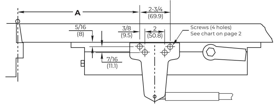
| A | B | ||||
|---|---|---|---|---|---|
| Opening | Inches | mm | Inches | mm | |
| to 120° | 9-1/2 | 241 | 3-3/4 | 95 | |
| 100° to 130° | 7 | 178 | 1-1/4 | 32 | |
*3400A and 3400MA covers cannot be used when door swings beyond 120°.
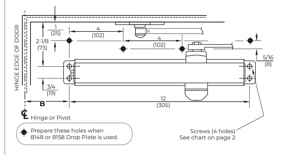
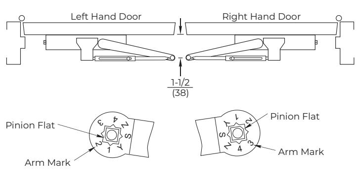
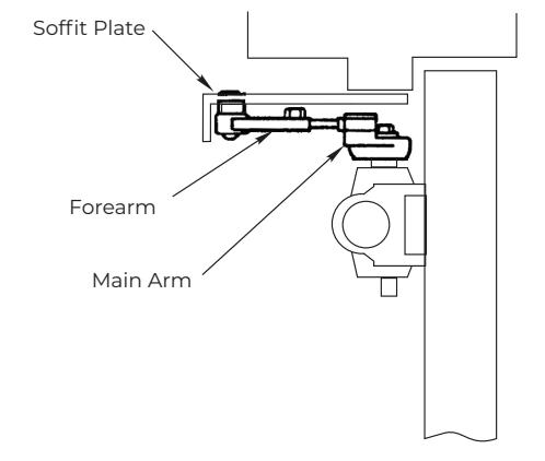
Figure 2
The ASSA ABLOY Group is the global leader in access solutions. Every day we help people feel safe, secure and experience a more open world.

ASSA ABLOY
Adjustments
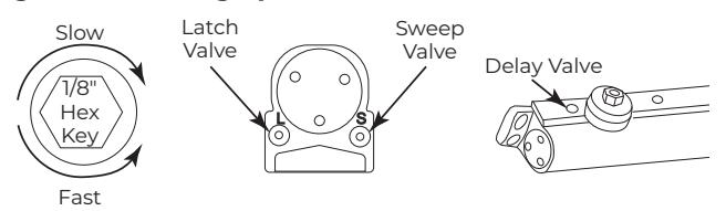
Control Valve Adjustments (Figure 3)
Closing Speed Controls (Figure 4)
- Valve "S" Controls Sweep Range
- Valve "L" Controls Latch Range
- Valve "D" (Optional for all models) Controls Delay Range
Opening Cycle
"Backcheck" valve controls the strength of cushioning in Backcheck Range. NEVER close this valve completely, it is not to provide a positive stop. (Figure 5 and Figure 6)
Figure 3 - Closing Speed Controls
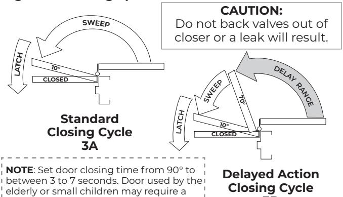
Figure 4 - Closing Speed Controls
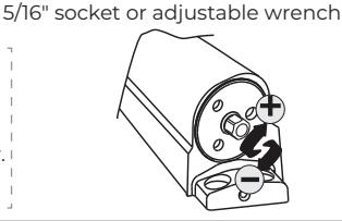
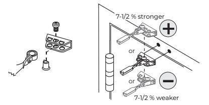
Closing Power Controls
longer closing time.
To increase power, turn Spring Adjustment shaft clockwise. A total of twenty (20) 360° turns of the nut will provide maximum power.
Factory set to ten (10) turns.
3 B
Arm Placement in Shoe
Covei
<u>Full cover</u>: Slide cover insert into the un-used cutout in cover. Install cover using screws provided.
<u>Narrow cover</u>: Install cover using screws provided. Install pinion cap onto pinion shaft by hand or with a Phillips screw driver - DO NOT OVER TIGHTEN .
<u>Full metal cover</u>: Fasten cover to mounting clips with screws provided.
<u>Metal Architectural Cover</u>: Remove cover insert where pinion is located. Install standoffs in ends of closer. Install cover using screws provided.
<u>Plastic Architectural Cover</u>: Slide cover insert into the un-used cutout in cover. Install standoffs in ends of closer. Snap cover over standoffs.
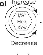
Figure 5 - Opening Door Control
CAUTION:
Do not back valves out of closer or a leak will result.
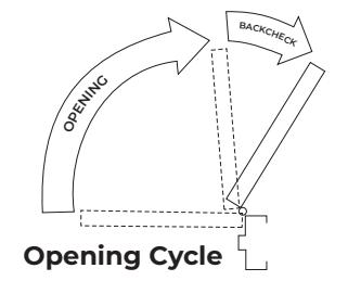
Figure 6 - Backcheck Control Increase
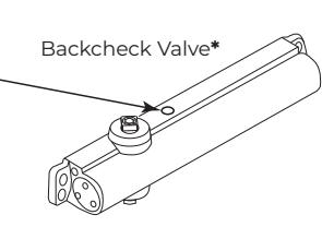
*Never close this valve completely
| Adjustment Chart (8381 & 8581 Only) | |||||||||
|---|---|---|---|---|---|---|---|---|---|
| DOOR | TYPE OF INSTALLATION | * |
Number of Turns Required
MAXIMUM DOOR SIZE |
||||||
|
32"
(81cm) |
36"
(91cm) |
42"
(107cm) |
48"
(122cm) |
||||||
| INTERIOR | Regular Arm Top Jamb |
urns
wer Shaft |
5 | 8 | 11 | 13 | |||
| Parallel Arm |
Full 360° tur
of 5/16" Pow Adjustment S |
7 | 10 | 13 | 16 | ||||
| EXTERIOR | Regular Arm Top Jamb | 7 | 10 | 13 | 16 | ||||
| Parallel Arm | 9 | 12 | 15 | 18 | |||||
| ** | |||||||||
* Twenty (20) 360° Turns Maximum Available Closer is shipped set at mid range setting = ten (10) turns
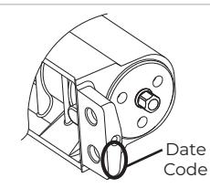
To Determine Date Code:
Technical Product Support: Monroe, NC 28112 USA
Phone: 877.974.2255 ext: 2
Techsupport.NortonRixson@assaabloy.com
NortonRixson.com