Norton Rixson 8000 Series Door Closer, 8000ST, PS8000ST, Slide Track, Push or Pull, Non-Hold Open or Hold Open I…_80-9380-2213-020
Open the original PDF document
View PDF8000ST Slide Track Door Closer
Pull or Push Side
Installation Instructions
Non Hold Open and Hold Open Models, With or without DA suffix (Delayed Action)
NOTES:
EDA

ASSA ABLOY
WARNING
This product can expose you to lead which is known to the state of California to cause cancer and birth defects or other reproductive harm. For more information go to: www. P65warnings.ca.gov.
An incorrectly installed or improperly adjusted door closer can cause property damage or personal injury. These instructions should be followed to avoid the possibility of misapplication or misadjustment.
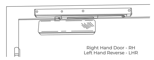
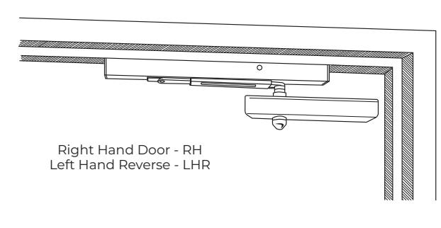
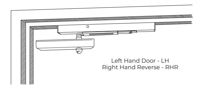
Left Hand Door - LH
Right Hand Reverse - RHR
Non Hold open Arm Models: 8301ST - 8501ST Series
PS8301ST - PS8501ST
Hold open Arm Models:
8301ST-H - 8501ST-H Series PS8301ST-H - PS8501ST-H

The closing force for series 8000ST door closers is adjustable from a size 1 to a size 6, as outlined in ANSI Standard Al56.4. When these series of door closers are installed and adjusted to conform to ADA reduced opening force requirements (5 lbs max.) for interior doors, they may not have adequate closing
READ AND FOLLOW ALL INSTRUCTIONS.
SAVE THESE INSTRUCTIONS.
force requirements (5 lbs max.) for interior doors, they may not have adequate closing force to reliably close and latch the door. Power adjustments charted on page 4 are recommended where possible, to ensure proper door control.
Use this instruction sheet for installation sequence and closer adjustments only.
- Use of an auxiliary door stop is always recommended.
– For Special Applications a separate door and frame
preparation template is packed with these instructions.

Refer to page 2

Refer to page 3

ASSA ABLOY
8000ST Series Side Track Door Closer
Pull Side Installation
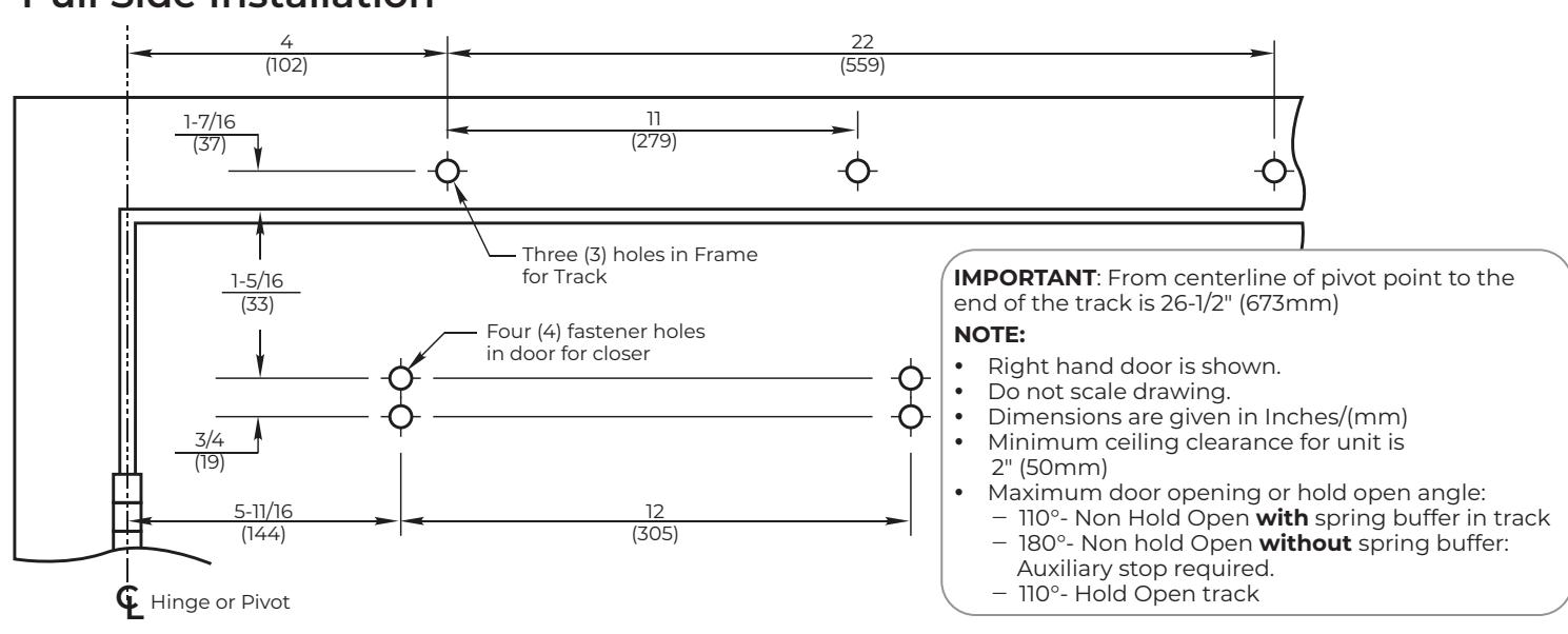
Installation Instructions
-
1. Use template to locate holes on door and frame:
- 4 on door for closer
- 3 on frame face for track assembly
- 2. Prepare door and frame for fasteners using chart on this page.
- 3. FOR 8301/8501 & 8311/8511 SERIES MODELS ONLY:
Set closer power for door size using chart below:
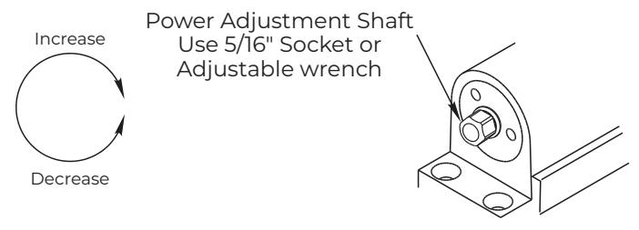
Power Adjust
Use 5/16" Socket or Adjustable Wrench for this adjustment.
Power Adjustment Chart for 8301/8501, 8311/8511 ONLY
| DOOR | Number of Turns Required MAXIMUM DOOR SIZE | ||||
|---|---|---|---|---|---|
|
32"
(81cm) |
36"
(91cm) |
42"
(107cm) |
48"
(122cm) |
||
| Interior Door | 2 | 3 | 5 | 7 | |
| Exterior Door | .3 | 5 | 7 | 9 | |
NOTE: Maximum of 20 turns (360°) of Power Adjust Shaft. Closer is shipped set at 10 turns.
4. Fasten closer body to door with power adjustment shaft toward lock edge of door.
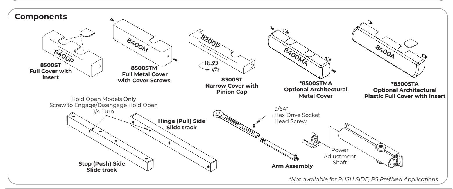
NOTE : If application has a full metal cover, 8500M, slide mounting clips under each end of closer before tightening screws.
- 5. Fasten slide track to frame face with open side facing down and spring buffer end toward hinge edge of door.
- 6. Adjust arm to shortest length and install 9/64" hex drive socket head screw from screw pack.
| Preparation for Fasteners | ||||||
|---|---|---|---|---|---|---|
| Fasteners |
Door or
Frame |
Drill-Sizes | ||||
| Standard | Self-Drilling |
Aluminum
or Metal |
No Drill Required | |||
| Screw | Wood | 3/16" (4.30mm) | ||||
|
1/4"-20
Machine Screw |
Metal |
Drill: #7 (0.201" dia)
Tap: 1/4"-20 |
||||
| Optional | Sleeve nuts |
Hollow
Metal |
9/32" (7mm) through;
3/8" (9.5mm) door face opposite of closer |
|||
| and bolts |
Aluminum
or Wood |
3/8" (9.5mm) through | ||||
|
Through-bolts
and grommet- nuts |
All |
9/32" (7mm);
3/8" (9.5mm) dia. x 3.8" (9.5mm) deep on door face opposite of closer |
||||
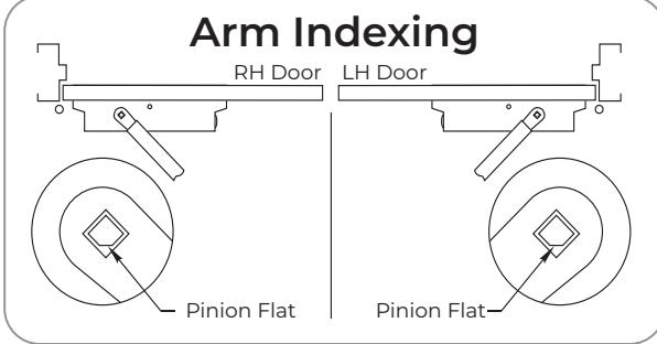
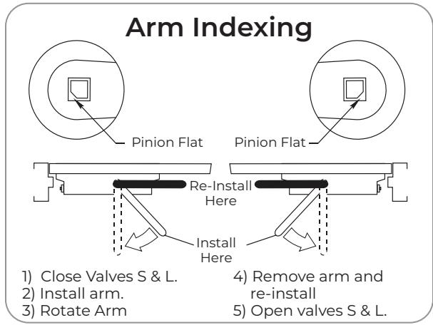
- 7. Place slide arm on pinion shaft using Arm Indexing instructions above.
- 8. Secure arm with arm washer and arm screw.
- 9. Insert arm stud into slide block in track assembly. Secure by pushing in on the retainer clip that extends from the slide block in the track, until it is flush with the slide block.
- 10. Adjust closer. (Refer to page 4)
8000ST Series Side Track Door Closer


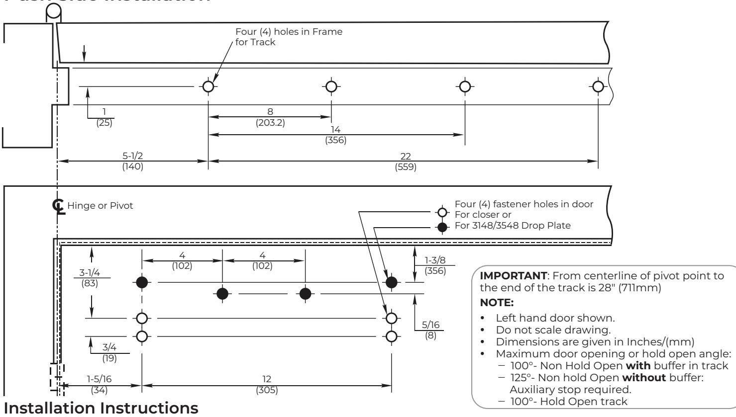
-
1. Use template to locate holes on door and frame:
- 4 on door for closer or drop plate
- 4 on frame soffit for track assembly
- 2. Prepare door and frame for fasteners using chart on page 2.
- 3. FOR PS8301/PS8501 & PS8311/PS8511 SERIES MODELS ONLY : Set closer power for door size using chart below:
Power Adjust
Use 5/16" Socket or Adjustable Wrench for this adjustment.
Power Adjustment Chart for PS8301/PS8501, PS8311/PS8511 ONLY
| DOOR |
Number of Turns Required
MAXIMUM DOOR SIZE |
||||
|---|---|---|---|---|---|
|
32"
(81cm) |
36"
(91cm) |
42"
(107cm) |
48"
(122cm) |
||
| Interior Door | 2 | 3 | 5 | 7 | |
| Exterior Door | 3 | 5 | 7 | 9 | |
NOTE: Maximum of 20 turns (360°) of Power Adjust Shaft. Closer is shipped set at 10 turns.
4. Fasten closer body to door with power adjustment shaft toward lock edge of door.
NOTE : If application has a full metal cover, 8500M, slide mounting clips under each end of closer before tightening screws.
- 5. Fasten slide track to frame face with open side facing down and spring buffer end toward hinge edge of door.
- 6. Adjust arm to shortest length and install 9/64" hex drive socket head screw from screw pack.
- 7. Place slide arm on pinion shaft using Arm Indexing instructions below.
- 6. Secure arm with arm washer and arm screw.
- 7. Insert arm stud into slide block in track assembly. Secure by pushing in on the retainer clip that extends from the slide block in the track, until it is flush with the slide block.
- 8. Adjust closer. (Refer to page 4)
The ASSA ABLOY Group is the global leader in access solutions. Every day we help people feel safe, secure and experience a more open world.

ASSA ABLOY
Closer Adjustments
Figure 1 - Attach Arm Stud to Slide
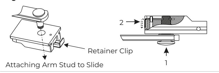
Figure 2 - Closing Power Control
Hvdraulic Controls
Figure 3A - Closing Cycle
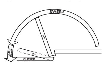
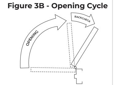
Figure 4 - Closing Speed
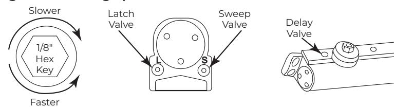
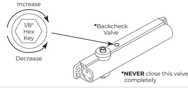
Figure 5 - Backcheck
Arm Attachment to Track:
Insert arm stud into slide block in track. Secure by pushing in on the retainer clip that extends from the slide block, until it is flush with the slide block. See Figure 1 .
Door Opening Angle and/or Hold Open Angle:
Remove 9/64" hex drive socket head screw from arm. Open door to desired angle and install hex-drive socket head screw into hole in adjusting rod that is aligned with the hole in the adjusting tube.
8301ST/8501ST Models are fully adjustable. For proper sizing see chart on page 2 for Pull Side, or page 3 for Push Side.
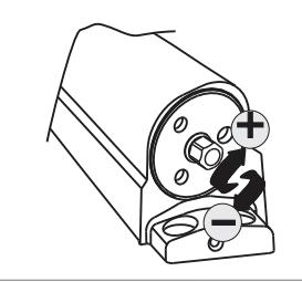
To adjust closer power – See Figure 2 . Increase or decrease power as necessary.
Closing Cycle (hydraulic control) See Figure 3A.
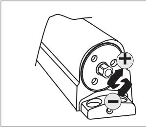
Valve "L" controls door speed in Latch range. Valve "S" controls door speed in Sweep range. Valve "D"-Optional-controls door speed in the Delay range.
Use 1/8" hex-key furnished and adjust as shown in Figure 4 .
Opening Cycle (hydraulic control) See Figure 3B.
Valve cushions (slows) door opening in the backcheck range. NOTE : Never close this valve completely or damage to closer may occur.
Use 1/8" hex-key furnished and adjust as shown in Figure 5 .
Installation of Cover:
- <u>Full cover</u>: Slide cover insert into the un-used cutout in cover. Install cover using screws provided.
- <u>Narrow cover</u>: Install cover using screws provided. Install pinion cap onto pinion shaft by hand or with a Phillips screw driver - DO NOT OVER TIGHTEN.
- Architectural plastic cover: Slide cover insert into the unused cutout in cover. Install standoffs in ends of closer. Snap cover onto standoffs.
On/Off Hold Open Feature:
Slotted screw, accessible thru hole in face of track, engages or disengages the hold open feature with 1/4 turn of the screw. See page 1 for location of screw.
Hold Open Power Adjustment:
If more hold open power is required, the power may be increased by turning the adjustment shaft in the end of the track nearest the hinges. Use 9/64" hex wrench provided and rotate adjustment shaft clockwise to increase holding power.
Technical Product Support: Monroe, NC 28112 USA
Phone: 877.974.2255 ext: 2
Techsupport.NortonRixson@assaabloy.com
NortonRixson.com