Norton Rixson 7900 Series Overhead Concealed Closer, 7970-B, 7970-OP, Non-Hold Open Installation Instructions_80-9379-1701-020
Open the original PDF document
View PDF7900 Series Overhead Concealed Door Closer
Security Models 7970-B & 7970-OP
Non-Hold Open, Standard Butt Hinges or Offset Pivots Installation Instructions


This product can expose you to lead which is known to the state of California to cause cancer and birth defects or other reproductive harm. For more information go to: www.P65warnings.ca.gov.
An incorrectly installed or improperly adjusted door closer can cause property damage or personal injury. These instructions should be followed to avoid the possibility of misapplication or misadjustment.
READ AND FOLLOW ALL INSTRUCTIONS. SAVE THESE INSTRUCTIONS.
NOTES:
- y For metal doors, 1-3/4" to 2-1/4" (45mm to 57mm) thick, hung in hollow metal frame.
- y Removable frame stop required unless frame rabbet exceeds 2-3/16" (56mm).
Typical Installation:
- ‒ One (1) track & closer position for all door opening angles.
- ‒ Easy arm attachment.

Non-Hold Open, Standard Butt Hinges or Offset Pivots
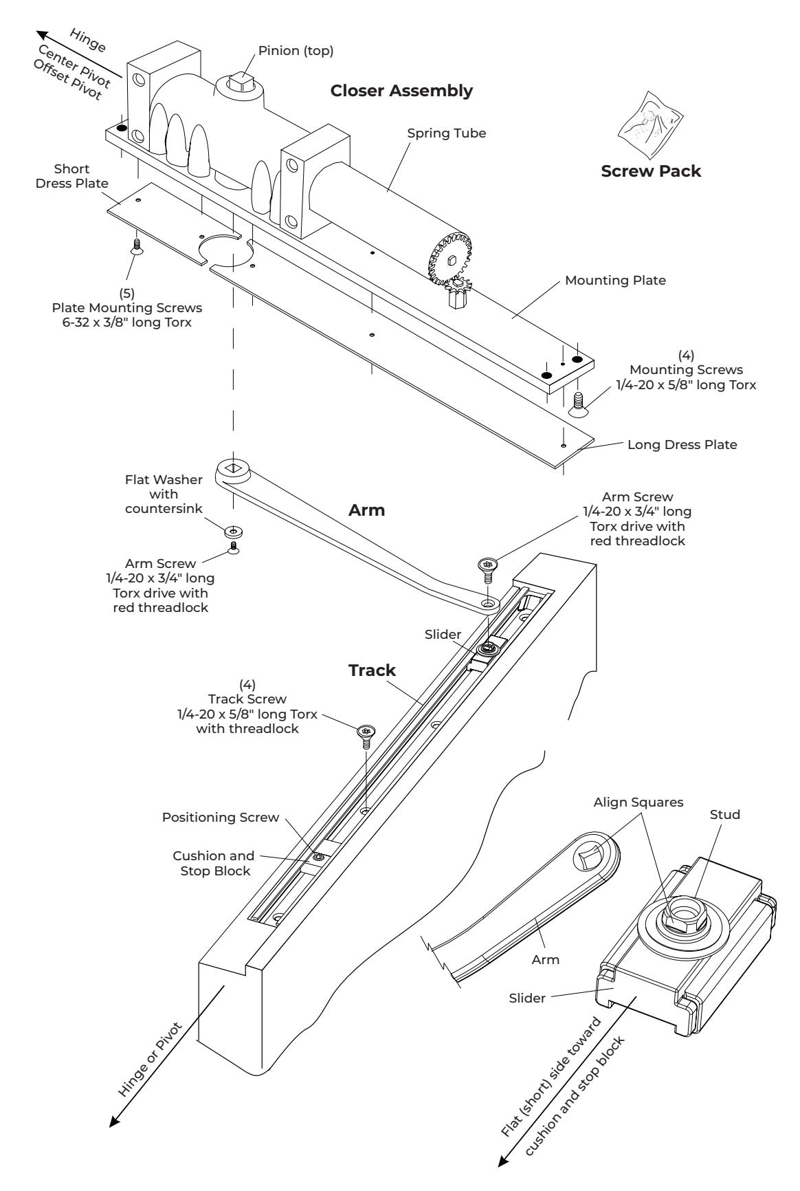
Assembly Components
Non-Hold Open, Standard Butt Hinges or Offset Pivots

Model 7970-B Template
Standard Butt Hinges
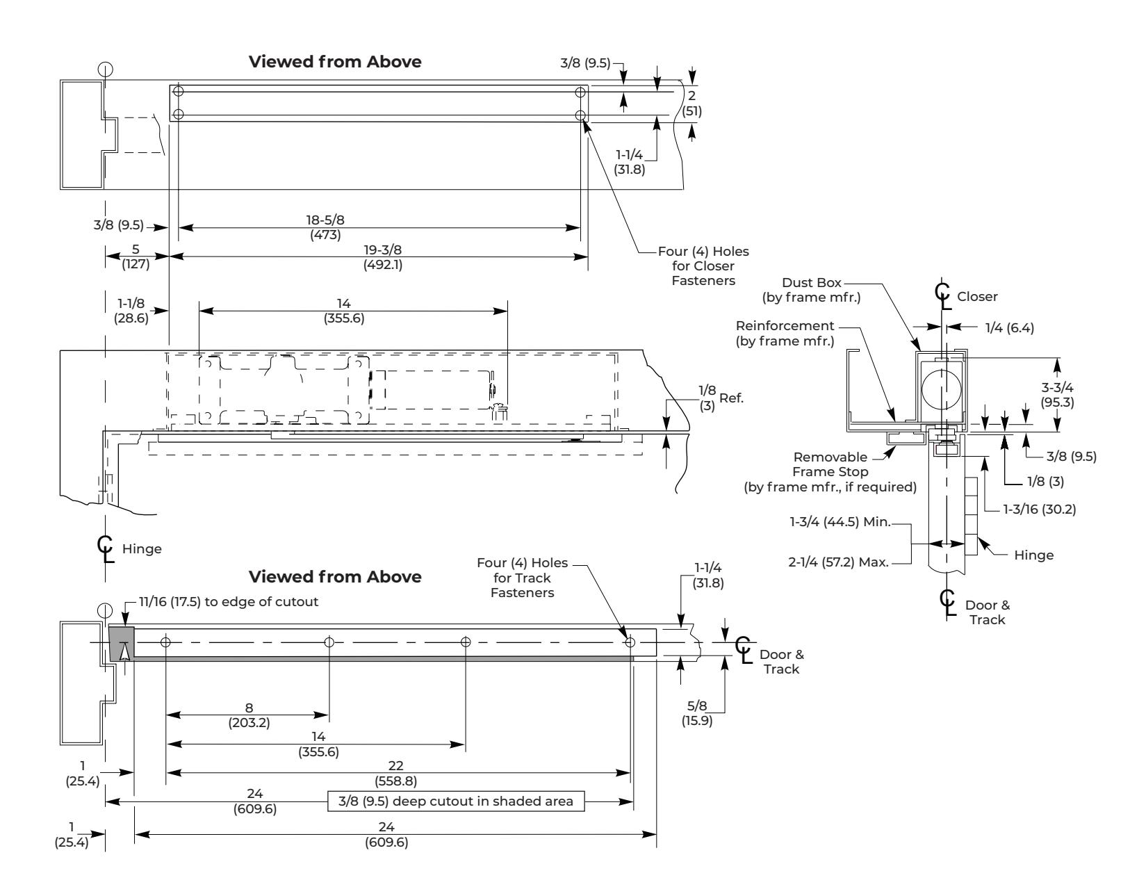
NOTES:
- y Do not scale drawing.
- y Left Hand door shown.
- y Hardware dimensions shown (not cutouts).
- y Dimensions are in inches (mm).
- y Minimum door width: 27" (0.70m)
- y Track: 24" (610mm)
- y Maximum width hinge: 5" (127mm)
| Fastener | Use | Preparation |
|---|---|---|
| 1/4-20 Machine | Metal frame & | #7 (0.201" dia.) or 5.10mm drill |
| Screw | Metal door | 1/4-20 tap |
| Track | Door Angle | Auxiliary Door | |
|---|---|---|---|
| Installation | 110° | 180° | Stop Required |
| Non-Hold Open |
With
Cushion & Stop Block |
Without
Cushion & Stop Block |
Opening
greater than 110° |
See Installation Sequence on page 5.

Non-Hold Open, Standard Butt Hinges or Offset Pivots
Model 7970-OP Template
Offset Pivots
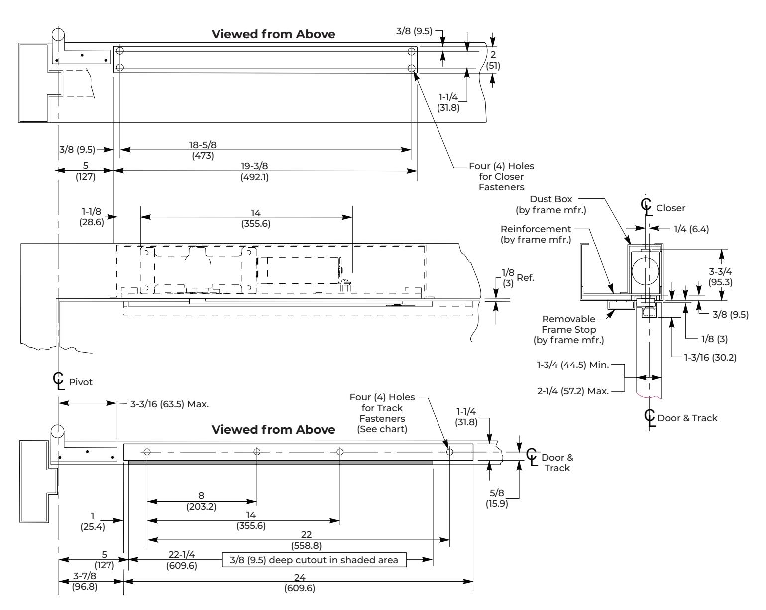
NOTES:
- y Do not scale drawing.
- y Left Hand door shown.
- y Hardware dimensions shown (not cutouts).
- y Dimensions are in inches (mm).
- y Maximum door swing is 95°. Auxiliary door stop (not supplied) is required for this application.
- y Standard track is 24" (610mm) long.
- y For doors less than 29" (736.6mm) wide. Contact factory for modification requirements.
| Fastener | Use | Preparation |
|---|---|---|
| 1/4-20 Machine | Metal frame & | #7 (0.201" dia.) or 5.10mm drill |
| Screw | Metal door | 1/4-20 tap |
See Installation Sequence on page 5.
Non-Hold Open, Standard Butt Hinges or Offset Pivots

Installation Sequence
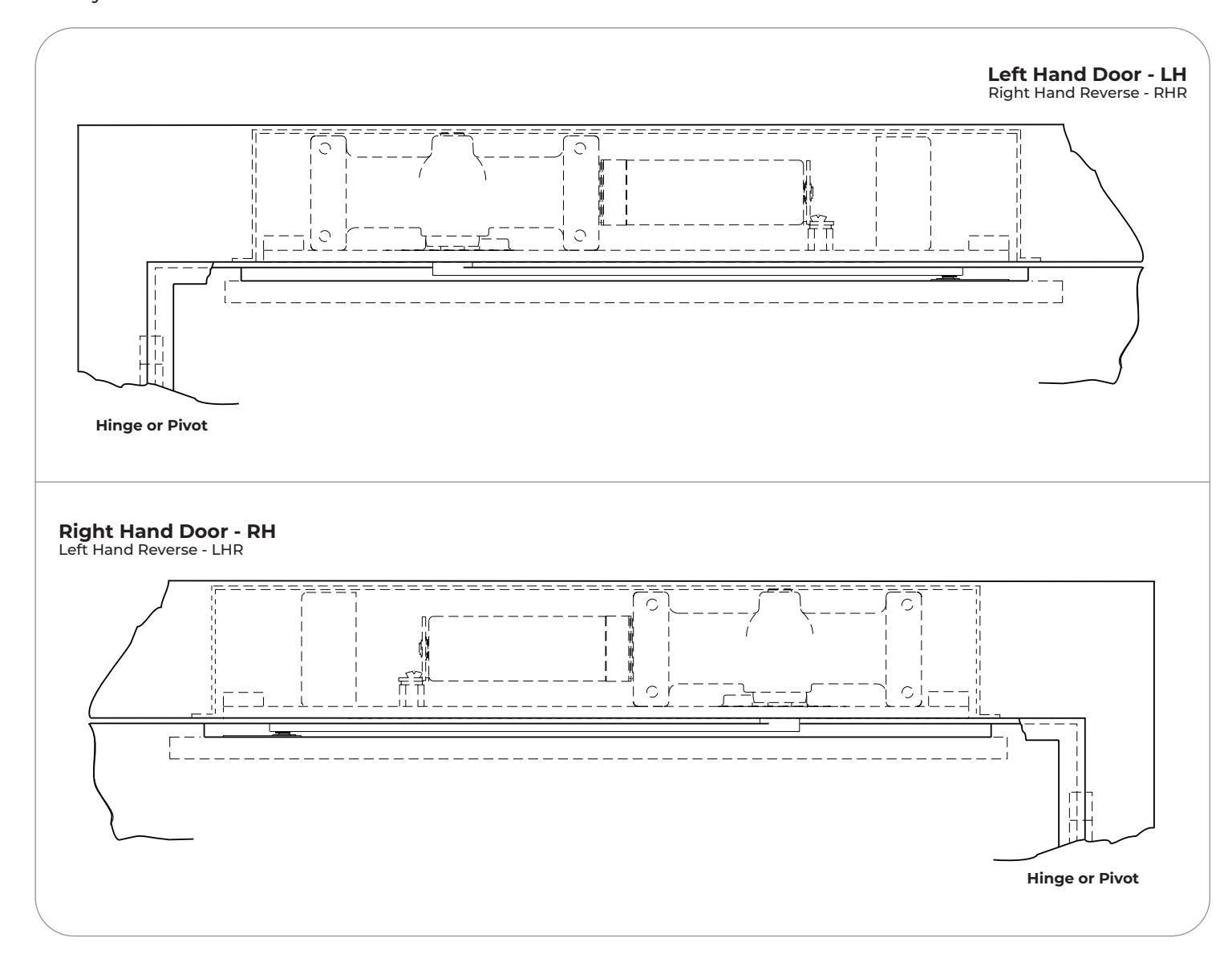
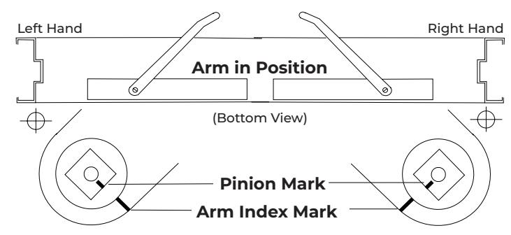
1. Determine hand of door.
Refer to page 1. Closers are handed. Hand of closer must match hand of door.
2. Use the template dimensions, locate and prepare holes and cutout in frame and door.
Refer to Model 7970-B Template on page 3 for Standard Butt Hinges.
Refer to Model 7970-OP Template on page 4 for Offset Pivots.
Prepare the frame for mounting closer.
Drill and tap four (4) holes for 1/4-20 machine screws.
Prepare door for track.
Prepare four (4) holes for 1/4-20 machine screws.
NOTE: Generally on new construction hardware cutouts are pre-made by suppliers.
3. Mount closer to frame.
Position spring tube away from hinge or pivot and mounting plate flush with frame rabbet. Secure with mounting screws.
4. Install arm on closer pinion. (see illustration below)
With arm counterbore facing down, align arm index mark with pinion index mark. Install arm onto pinion. Secure with washer and 1/4-20 x 3/4" long flathead Torx drive arm screw with red threadlock.
5. Install track on door.
Place the assembled track into door cutout with open side facing up, cushion and stop block toward hinge or pivot. Move the slider to the opposite end of the track (see illustration on page 2). Secure track with four (4) 1/4-20 machine screws.
6. Connect arm to track.
Open door to approximately 5" (127mm), rotate arm to slider and place end on stud. Use a screwdriver to align the square on the slider's stud with the arm square (see illustration on page 2) Push down on arm to seat stud and to prevent stud from rotating. Secure with arm screw, 1/4-20 x 3/4" long flat head Torx with red threadlock.
7. Determine door opening angle.
Refer to pages 3 and 4.
8. Set door opening angle.
Open the door to the desired angle. With the door held at that position, slide cushion and stop block against slider. Tighten the stop position screw (large set screw) with the 3/16" hex wrench (provided) until secure. Release door.
9. Adjust closer.
Refer to page 6. Once adjusted, install dress plate.

Closer Adjustment
Standard Door Closer
Mounting Plate Base
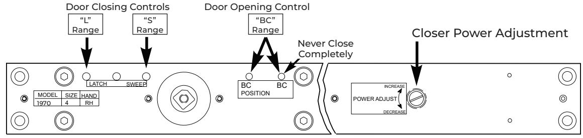
y Closer Controls:
Closer controls are accessible through mounting plate for closer adjustment. Use 1/8" (3mm.) hex-key for valve adjustments. Use a standard screwdriver for power adjustment.
y Power Adjustment:
Power Adjustment permits increasing door closing force. Controlled by slotted screw marked " POWER ADJUST. "
y Closing Speed:
Closing Speed controlled by valves marked " SWEEP " and " LATCH ". ATTENTION : Adjust closing speed time to between 4 to 7 seconds from 90°. Use of the door by people with disabilities, elderly, or small children may require greater closing time.
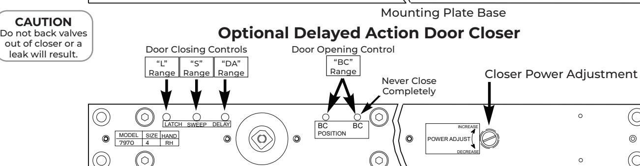
y Delayed Action:
Delayed Action option permits door to creep from fully open to about 70°. Creeping time controlled by valve marked " DELAY ".
y Backcheck:
Backcheck cushions or slows the opening of a door that is forced to travel faster than conditions require. Backcheck controlled by valves marked " BC POSITION " (open for backcheck start at a greater door opening angle) and " BC " (for adjusting backcheck intensity). Never close BC valve completely.
y Optional Enhanced Backcheck:
Optional Enhanced Backcheck provides adjustable backcheck intensity beginning at approximately 15° of the door opening cycle. Backcheck positioning valve is omitted when this feature is provided.
y Install Dress Plate:
Refer to page 2.
Technical Product Support: Monroe, NC 28112 USA Phone: 877.974.2255 ext: 2 Techsupport.NortonRixson@assaabloy.com
NortonRixson.com
Backcheck Closing Controls Opening Controls Latch Sweep Delayed Action