Norton Rixson 7570 Series Security Door Closer, PR7570, PR7770, Parallel Rigid Arm, Non-Hold Open or Hold Open I…_80-9377-0621-020
Open the original PDF document
View PDFPR7570/PR7770 Series Security Door Closer
Non Hold Open or Hold Open Parallel Arm Installation Instructions


This product can expose you to lead which is known to the state of California to cause cancer and birth defects or other reproductive harm. For more information go to www.P65warnings.ca.gov.
An incorrectly installed or improperly adjusted door closer can cause property damage or personal injury. These instructions should be followed to avoid the possibility of misapplication or misadiustment.
Note: For Special Applications a separate door and frame preparation template is packed with these instructions. Use this instruction sheet for installation sequence and closer adjustments only.
• For Hold Open function, consult factory or authorized representative
| Series | Droduct Type | ||
|---|---|---|---|
|
Sized*
Closer |
Multi-Sized **
Closer |
- Product Type | |
| PR7770 | PR7570 | Security Door Closer (Door Closer with both a Security Cover and Security Arm) | |
- PR7770 Series are sized door closers with 50% power increase capability. Power size 2 weakest power, power size 6 strongest.
- PR7570 Series can be adjusted from power size 1 thru 6.
- *For closers with or without "DA" suffix Delayed Action closing feature
**Note:

The closing force for series 7500 door closer is adjustable from a size 1 to a size 6, as outlined in ANSI Standard A156.4. When this series of door closer is installed and adjusted to conform to ADA reduced opening force requirements (5 lbs max.) for interior doors, it may not have adequate closing force to reliably close and latch the door. Power adjustments charted on pages 3,4 and 5 are recommended where possible, to ensure proper door control.
Push Side Installation
Closer mounts on opposite to hinge (push) side of door.
- Door closer cover is handed and cannot be reversed. All other components are non handed.
- It is recommended that the door, on which the door closer will be installed, be hung on ball bearing hinges or offset pivots. Door must swing freely.
- A separate door stop, supplied by others, is recommended to prevent damage to the door closer, closer arm, or to the door, frame or adjacent walls.
- · Door and Frame must be properly reinforced, or use of special fasteners employed, to prevent the mounting screws from pulling out.
- All dimensions are given in inches with corresponding metric dimensions (mm) in parenthesis.
- Torx tamper resistant drive machine screws are normally supplied with this product.
PR7570/PR7770 Series (Parallel Arm Mount)
| Preparation for Fasteners | ||||||||
|---|---|---|---|---|---|---|---|---|
| Fasteners |
Door or
Frame |
Drill-Sizes | ||||||
| Standard |
1/4" - 20
Machine Screw |
Metal |
Drill: #7 (0.201" dia.)
Tap: 1/4" - 20 |
|||||
| Optional |
Sleeve Nuts
and Bolts (SNB) |
Hollow
Metal |
9/32" (7 mm); through
3/8" (9.5 mm) on door or transom-face opposite to closer |
|||||
|
Aluminum
or Wood |
3/8" (9.5 mm) through | |||||||
• Set closer power for door size using chart below. Install closer per instructions
| Power Adjustment Chart | ||||||||||
|---|---|---|---|---|---|---|---|---|---|---|
| DOOR |
PARALLEL ARM
INSTALLATION |
* | MAXIMUM DOOR SIZE | |||||||
|
32"
(0.81 m) |
36"
(0.9 m) |
42"
(1.1 m) |
48"
(1.2 m) |
|||||||
| INT |
TURNS FROM
ZERO |
0 | 3 | 5 | 8 | |||||
| EXT | PR7570 | 4 | 6 | 8 | 12 | |||||
| INT | PR7770 | 0 | 2 | 5 | 8 | |||||
| EXT | 2 | 5 | 8 | 11 | ||||||
*16 -360° TURNS MAXIMUM AVAILABLE
with the proper pre-load applied to the arm then adjust spring power. The power adjustment will not work properly if the closer spring is not pre-loaded.
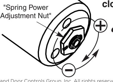
To increase power, use 11/16" wrench to turn power adjustment nut clockwise. To decrease power, turn nut counter clockwise.
DO NOT use a power drill or driver to turn adjustment nut.This will damage closer and void

PR7570/PR7770 Series (Parallel Arm Mount)

Installation Sequence
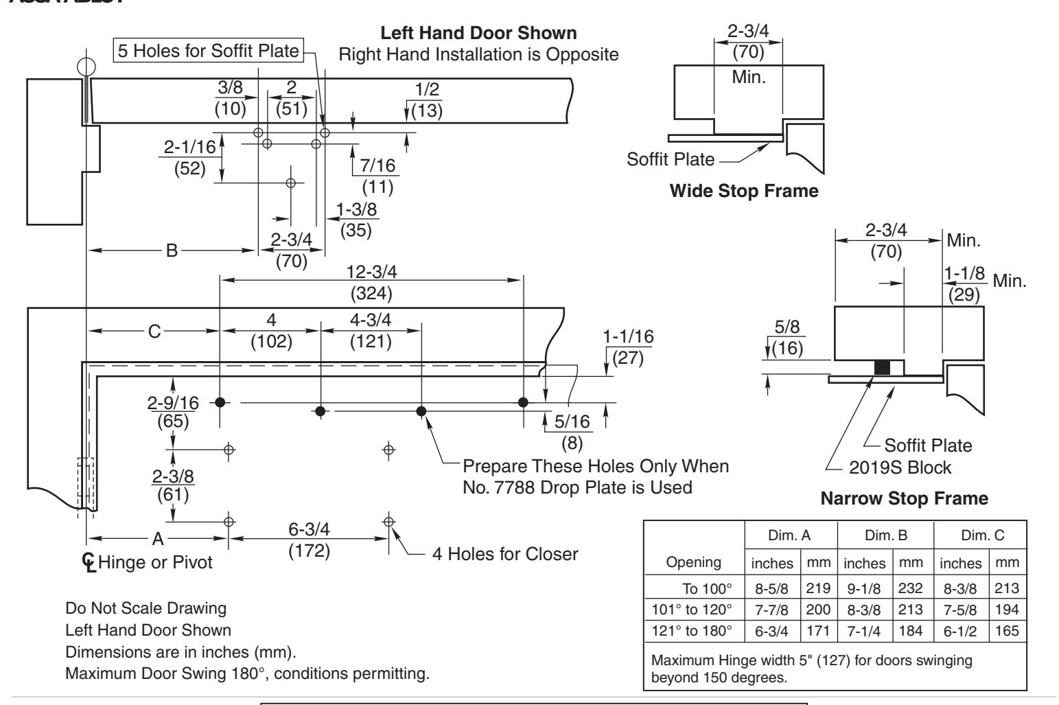
- Use template on page 2 to locate holes on door and frame: 4 on door for closer or drop plate. 5 on underside of frame stop for soffit plate.
- Prepare door and frame for fasteners using chart on page 2.
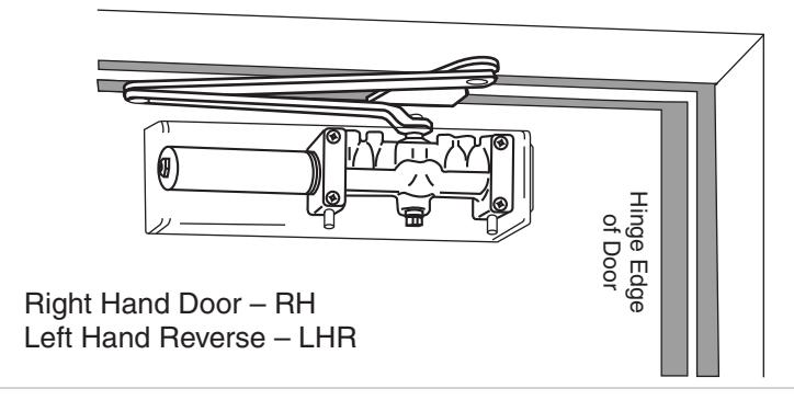
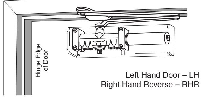
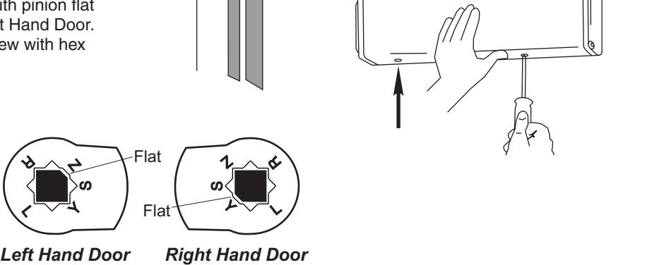
- Mount closer on door. (A drop plate is available for use on doors having narrow top rails) Power Adjustment Nut should be away from hinge. Valves are DOWN for Left Hand Door . Valves are UP for Right Hand Door .
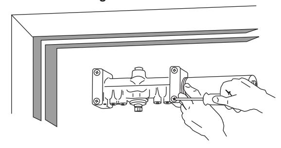
• Use 1/8" hex wrench to close valves. Turn Clockwise. For STANDARD CLOSER , close valves 'S/D' and 'L'. DELAYED ACTION CLOSER , close valves 'S' and 'L'.
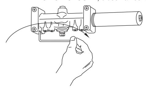
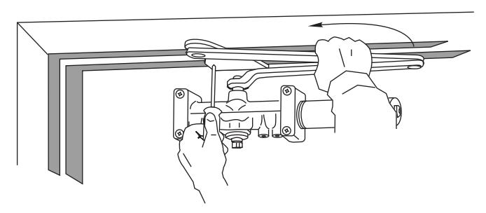
• With door closed, use wrench to rotate pinion shaft as illustrated below.
Caution: Closer arm is under spring tension and may be difficult to rotate.
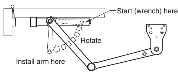
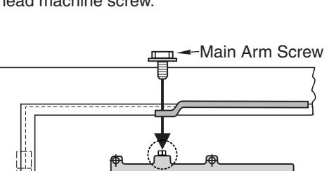
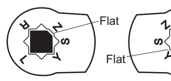
• Place main arm on shaft, aligning mark on arm with pinion flat on pinion shaft; "Z" for Left Hand Door; "Y" for Right Hand Door. Secure with 1/4-20 x 1/2" round head machine screw with hex head machine screw.

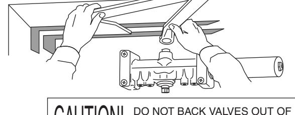
CAUTION! DO NOT BACK VALVES OUT OF CLOSER OR A LEAK WILL RESULT
- Reopen valves closed in Step 2. Turn Counterclockwise
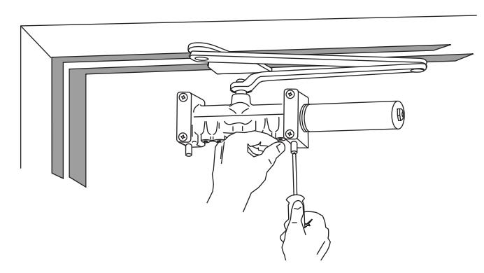
- With door closed, align soffit plate with mounting holes in frame. Fasten soffit plate to frame with flat head screws provided.
- Adjust closer per instructions on page 4 before installing cover
Install Cover:
• Screw standoffs into holes in closer.
• Fasten cover to closer with 4 #8-32x1/4 round head screws provided.
The ASSA ABLOY Group is the global leader in access solutions. Every day we help people feel safe, secure and experience a more open world.

Adjustments
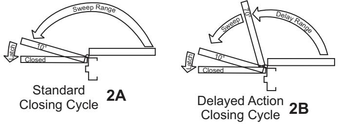
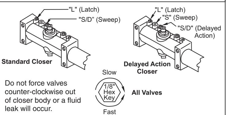
Closing Speed Controls (Figure 2A or 2B and 3.)
- Valve "S/D" Controls Sweep Range on Standard closer (or Delay Range on Delayed Action closer).
- · Valve "L" Controls Latch Range.
- Valve "S" Controls Sweep Range only on Delayed Action closer.
Closing Power Control Figure 1 PR7570 Only: Set closer to desired size. For recommended sizes, refer to the Power Adjustment Chart on page 2. Install closer per instructions with the proper pre-load applied to the arm then adjust spring power. The power adjustment will not work properly if the closer spring is not pre-loaded. To increase power, use 11/16" wrench to turn power adjustment nut clockwise. To decrease power, turn nut counter clockwise. DO NOT use a power drill or driver to turn adjustment nut. This will damage closer and void warranty.
Closing Speed Controls Figure 2
Adjust Closing Speed Time to between 3-7 seconds from 90°. Use of door by handicapped, elderly or small children may require greater closing time.
Figure 3 Closing Speed Controls
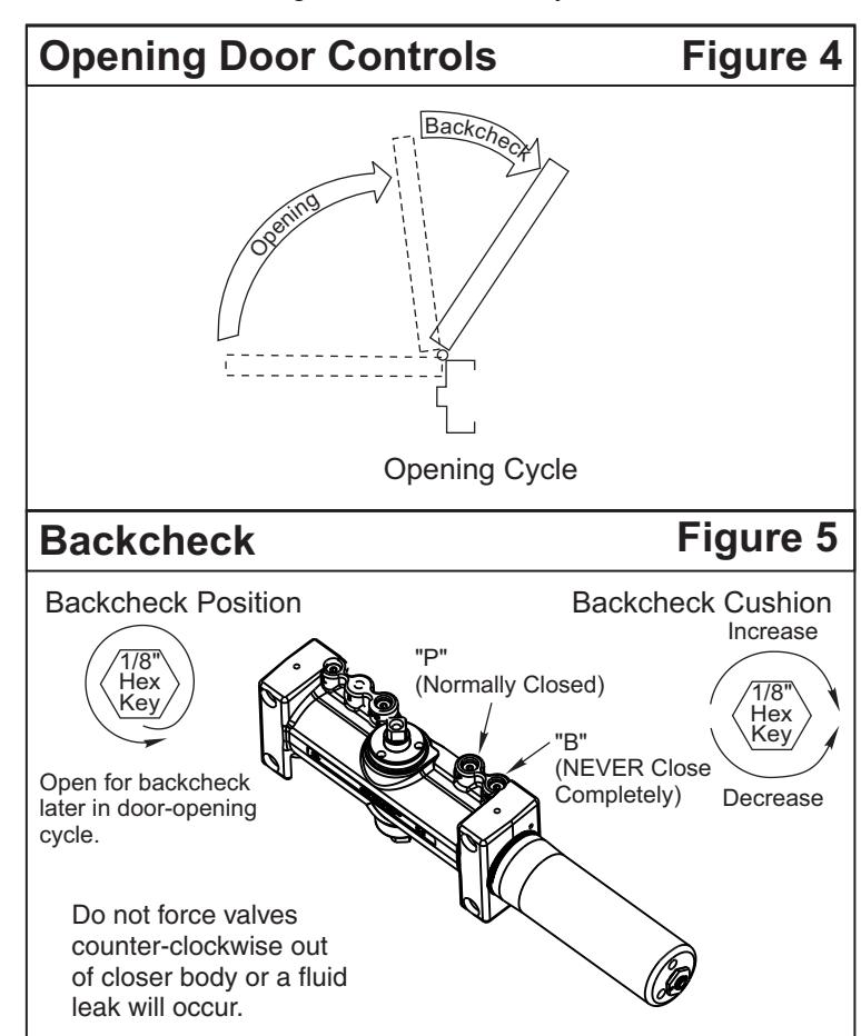
Opening Door Control (Figure 4.)
- Backcheck ("B") valve controls the hydraulic resistance to door opening. NEVER close this valve completely – it is not to provide a positive stop.
- Backcheck position ("P") valve controls the door angle where backcheck cushioning starts. Valve normally closed.
Technical Product Support: Monroe, NC 28112 USA Phone: 877.974.2255 ext: 2
Techsupport.NortonRixson@assaabloy.com
NortonRixson.com