Norton Rixson 7200 Series Door Closer,7290MPI,7290MPS Overhead Concealed Closer,Rigid Slide Arm Installation Ins…_80-9372-1071-020
Open the original PDF document
View PDF

ASSA ABLOY
Support Unit Models
7290 MPI (Infinite Hold Open Range) 7290 MPS (Selective Hold-Open Range)
80-9372-1071-020 (01-14)
Multi-Point Electromechanical Overhead Concealed Closer Holder Releasing Device with Rigid Slide Arm
For wood or metal doors 1- 3/4" to 2 -1/4" (45-57mm) thick Hung in a hollow metal frame Standard butt hinges
CAUTION
An incorrectly installed or improperly adjusted door closer can cause property damage or personal injury. These instructions should be followed to avoid the possibility of misapplication or misadjustment.
Typical Installation
- One track & closer position for all door opening angles
- Easy arm attachment
- Removable Frame Stop Required*-Not Shown
Hinge or Pivot
Left Hand Door-LH Right Hand Reverse-RHR
Right Hand Door-RH Left Hand Reverse-LHR
*Not required when frame rabbet exceeds 2-3/16" (56mm).
Hinge or Pivot
Model 7290MPI/7290MPS Template Standard Butt Hinges
Multi-Point Electromechanical Overhead Concealed With Rigid Slide Arm

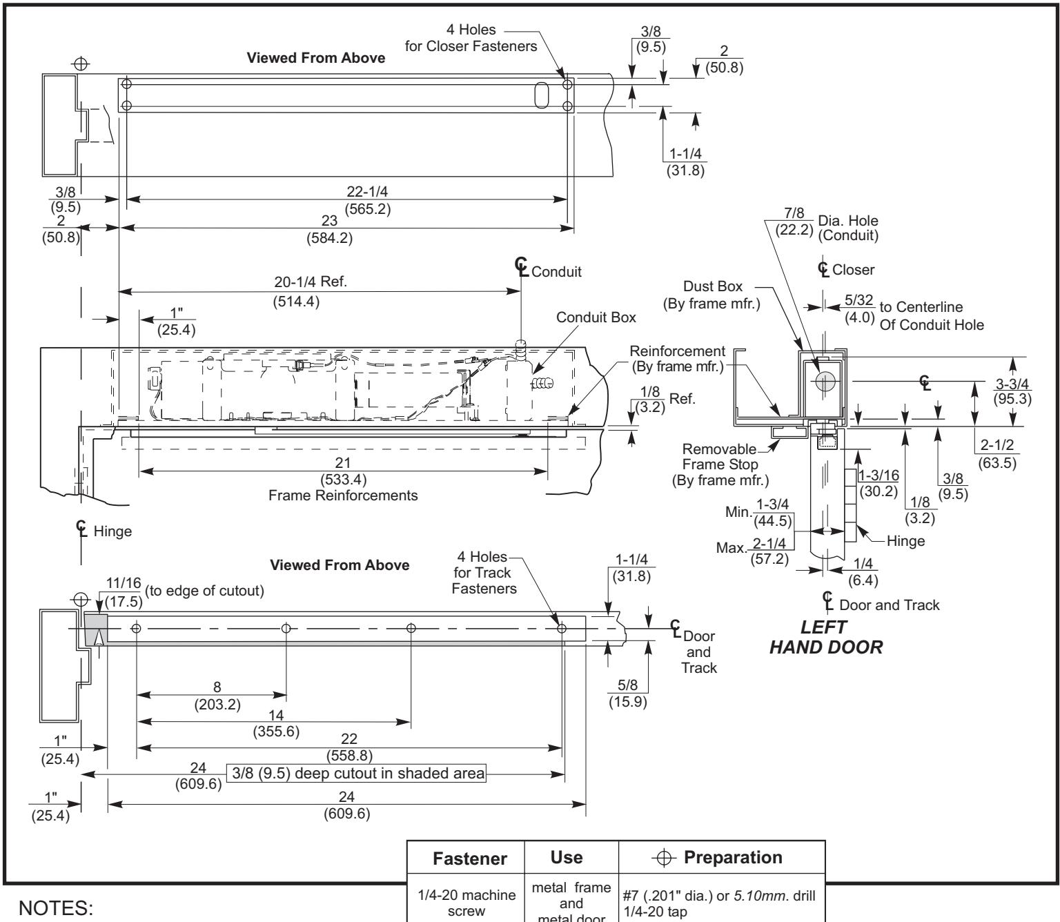
- · Do not scale drawing.
- Left hand door shown.
- Hardware dimensions shown (not cutouts).
- Dimensions are in inches (mm).
- Minimum door width 27" (685.8).
- Track 24" (609.6) long.
- Maximum width hinge is 5" (127).
| Fastener | Use | → Preparation | ||
|---|---|---|---|---|
| 1/4-20 machine screw |
metal frame
and metal door |
#7 (.201" dia.) or 5.10mm . drill 1/4-20 tap | ||
| #14 wood screw |
wood
door |
7/32" or 5.5mm. drill | ||
| Track Installation | ||||||
|---|---|---|---|---|---|---|
| Door A | Auxiliary Door | |||||
| 110° | 180° | Stop Required | ||||
| With | Without | Opening | ||||
| Cushion and | Cushion and | greater | ||||
| stop block | Stop block | than 110° | ||||
See installation sequence on pages 4 & 5.
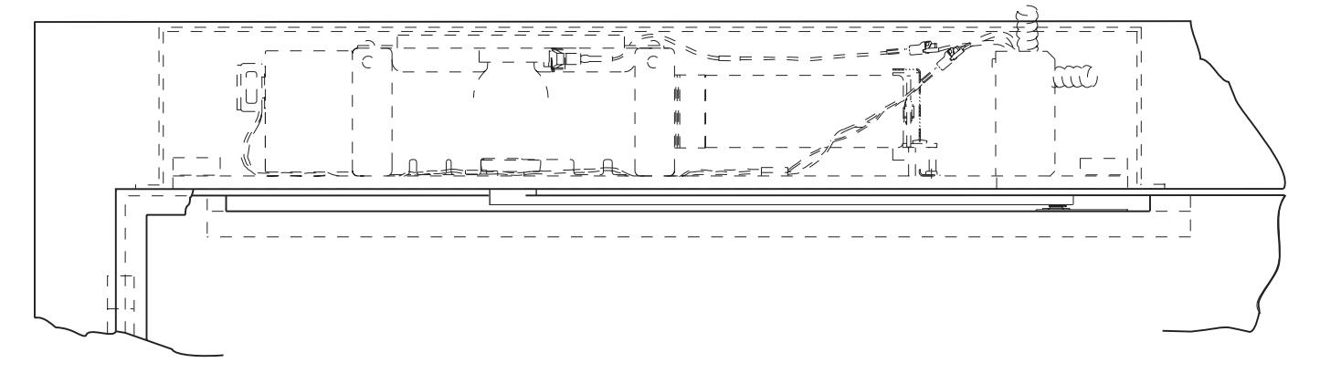
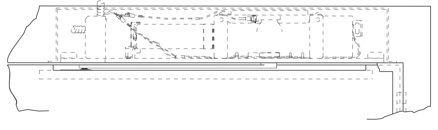
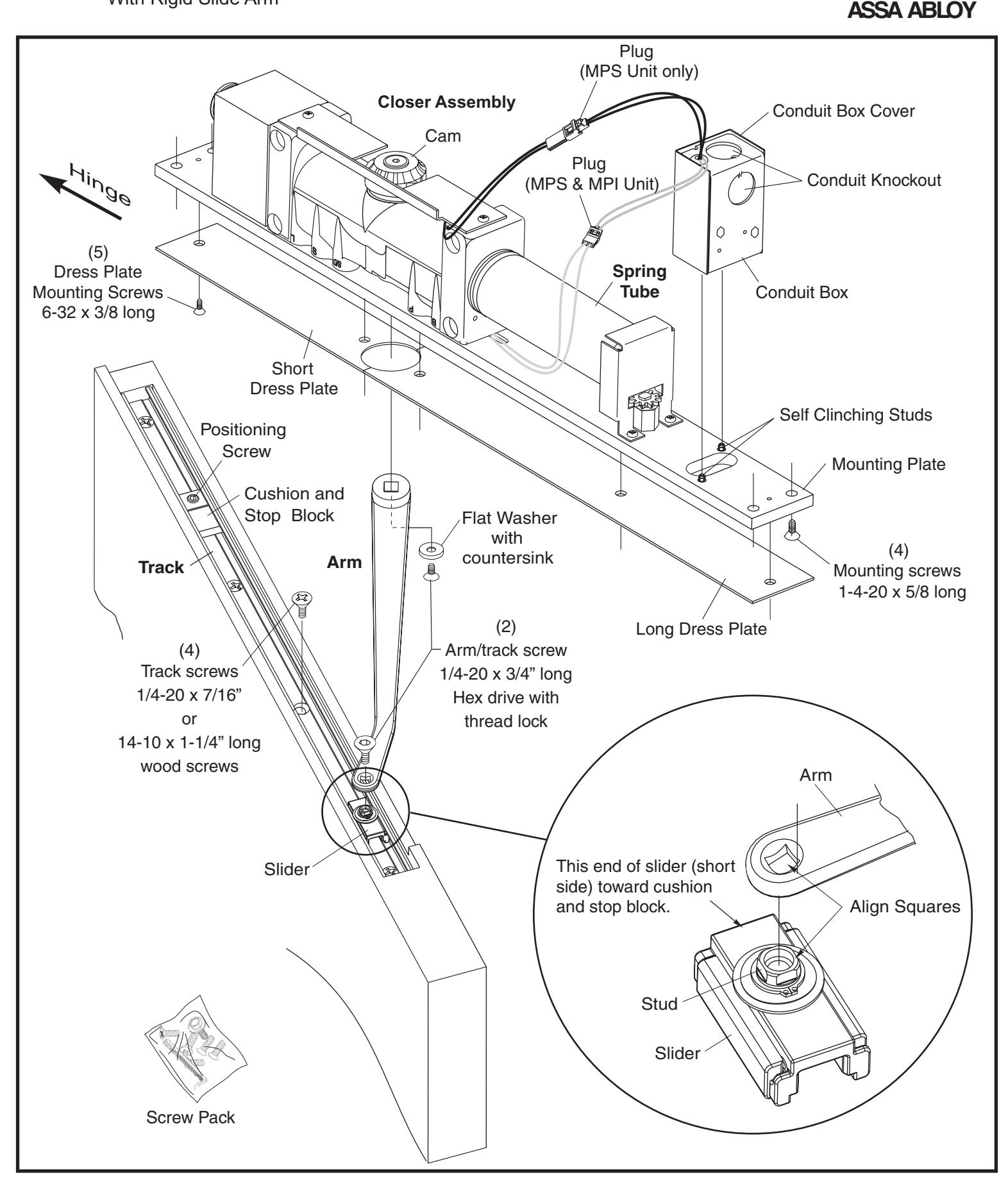
Components Model 7290MPI/7290MPS
Multi-Point Electromechanical Overhead Concealed With Rigid Slide Arm

Installation Sequence
Note: Read instructions entirely prior to installation.
Norton
ASSA ABLOY
Door/Frame Prep:
- Determine hand of door from illustration on page 1. Closer are handed. Hand of closer must match hand of door.
- Using template dimensions on page 2, locate holes and cutouts in frame and door, unless a separate template has been supplied for your application.
Door:
Prepare door for track. Drill and tap (4) holes for 1/4-20 machine screws.
Frame:
Prepare the frame for mounting closer. Drill and tap (4) holes for 1/4-20 machine screws or #14 wood screws.
Note: Generally on new construction hardware cutouts are made by suppliers at their shop.
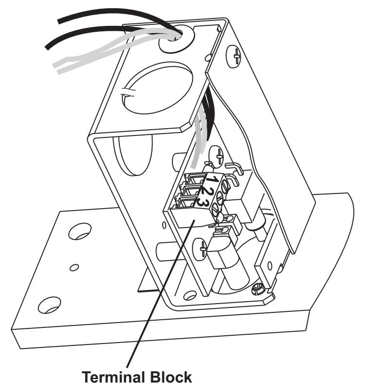
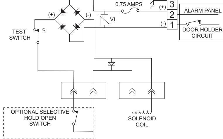
Wiring:
- Wiring of switch must be in compliance with N.E.C. Class 2 wiring specifications.
- Voltage to unit must be the same as shown on the unit: 24 Volts AC/DC or 120 Volts AC, 60hz. Voltage must be within a range of plus 10% and minus 15% of the unit's stated voltage.
- Pull hook-up box off mounting plate's self clinching studs, disconnect plugs and remove hook-up box cover.
- Anchor conduit at 1 or 2 hook-up box knockouts.
- Secure power input leads to terminal lock, positions #1 and #2 as shown.
SPECIFICATIONS
| 120VAC | 24VAC | 24VDC | |
|---|---|---|---|
| Voltage |
120V 132V MAX.
102V MIN. |
24V 26.4V MAX. 20.4V MIN. | 24V 26.4V MAX. 20.4V MIN. |
| Current | .035 AMPS | .070 AMPS | .070 AMPS |
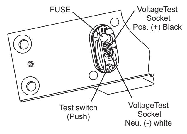
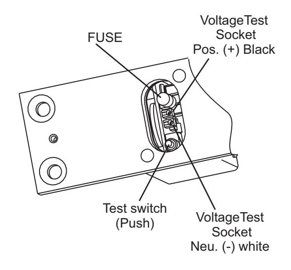
FUSE
Reconnect sockets
- a. Connect plug with white leads from solenoid for MPI and MPS units.
- b. Connect plug with black leads from cam switch if used.
Replace hook-up box cover and secure with (2) screws.
Reattached hook-up box to mounting plate by aligning (2) holes at bottom of hook-up box with (2) self clinching studs. See illustration on page 3.
Installation Sequence con't

- Determine door opening angle See page 2 and below.
- units will hold door at virtually any degree of door opening from • Series 7290MPI: Infinite Hold Open 5° to 175°.
- Selective Open Hold units are shipped with hold open set at • Series 7290MPS: approximately 85°. Hold open can be set from 5° to 175°.
The hold open position can be increased or decreased by loosening the cam screw, rotating the cam to the new setting and tighten cam screw. See chart below for cam settings where hold open range will start.
the hinge side face of door. • Align letters on hold open cam with "V" centerline of switch rocker. Choose row of letters on cam that are closest to
| Setting | G | H | J | K | L | M |
|---|---|---|---|---|---|---|
|
Door
Angle |
15º | 30º | 45º | 60º | 90º | 135º |
NOTE:Verify setting of cam before mounting closer to the frame.
• Mount closer to frame.
Position spring tube away from hinge and mounting plate flush with frame rabbet. Secure to frame reinforcements with (4) 1/4 -20 x 5/8 screws. Use care to avoid damaging or pinching wires.
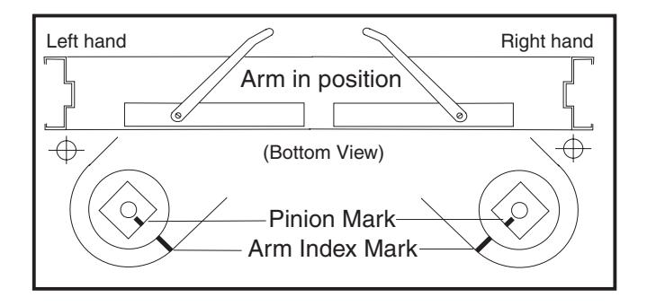
• Install arm on closer pinion (see illustration below) Position arm counterbore facing down with index mark aligned with pinion index mark. Install onto pinion. Secure with washer and flat head arm screw with thread lock (see page 3).
• Install track in door.
Place the assembled track into door cutout with open side up, cushion and block if used, toward the hinge. Move slider to the opposite end of track (see illustration, page 3). Secure track with (4) 1/4-20 machine screws. stop
• Connect arm to track. Open door to approximately 5" (127mm), rotate arm to slider and place end on stud. Use a screw driver to align the square on slider's stud with the arm square (see illustration on page 3). Push down on arm to seat stud and to prevent stud from rotating. Secure with arm/track screw, 1/4-20 x 5/8" long flat head hex drive with thread lock.
Model 7290MPI/7290MPS Closer Adjustment
Multi-Point Electromechanical Overhead Concealed With Rigid Slide Arm
CAUTION:
Do not back valves out of closer or a leak will result.
- Closer Controls accessible through mounting plate for closer adjustment: Use 1/8" (3mm.) hex-key for valve adjustments. Use standard screwdriver for power adjustment.
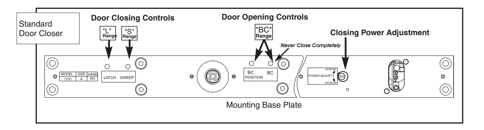
- Power Adjustment permits increasing door closing force. Controlled by slotted screw marked "P.A."
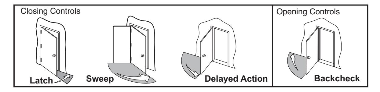
- Closing Speedcontrolled by valves marked "SWEEP" and "LATCH". Attention: Adjust closing speed time to between 4 to 7 seconds from 90°. Use of the door by handicapped, elderly, or small children may require greater closing time.
- Backcheck cushions or slows the opening of a door that is forced to travel faster than conditions require. Backcheck controlled by valves marked "BC POSITION" (open for backcheck start at a greater door opening angle) and "BC" (for adjusting backcheck intensity). Never close "BC" valve completely.
- Optional Enhanced Backcheck provides adjustable backcheck intensity beginning at approximately 15° of the door opening cycle. Backcheck positioning valve is omitted when this feature is provided.
- Hold Open Check. Turn power to the unit "On". Open door to the hold open position. Manually pull door out of hold open and release, door should close.
- Hook-Up Box Testing. Open door to the hold open position. Depress "Test Switch" button on Hook-up Board, accessible through cutout in hook-up box and mounting plate (see illustration at right). Door should close.
- Install short and long dress plates with (5) 6-32 screws.