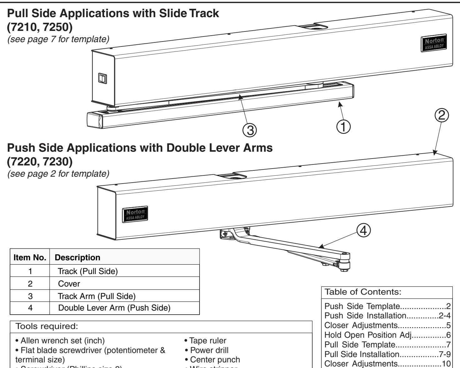
Norton Rixson 7200 Series Door Closer, 7210, 7250 (Pull Side), 7220, 7230 (Push side) Installation Instructions_80-9372-0100-020
Open the original PDF document
View PDF

7200 Series Multi-Point Hold Open Installation and Instruction Manual
ASSA ABLOY
- Screwdriver (Phillips size 2)
- Wire stripper
Use screw pack and hardware provided to mount operator.
Requirements:
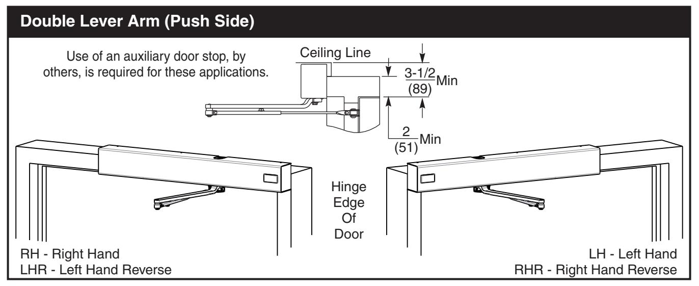
- Units are handed. Hand of unit and hand of door must be the same.
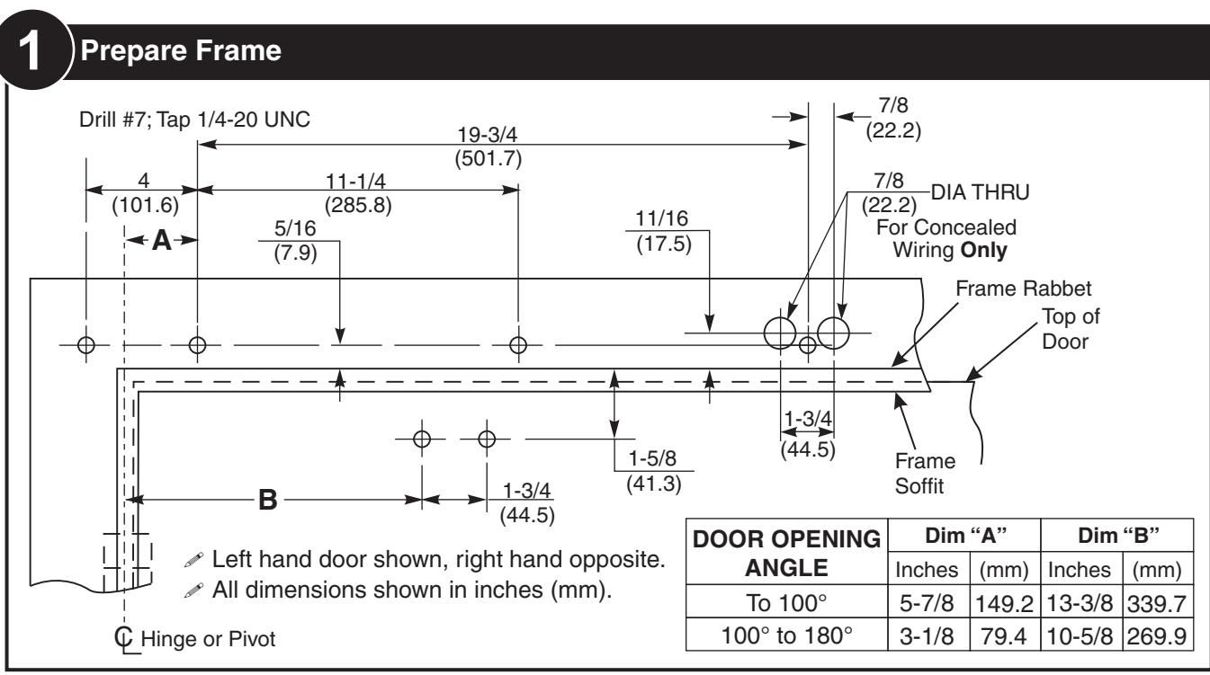
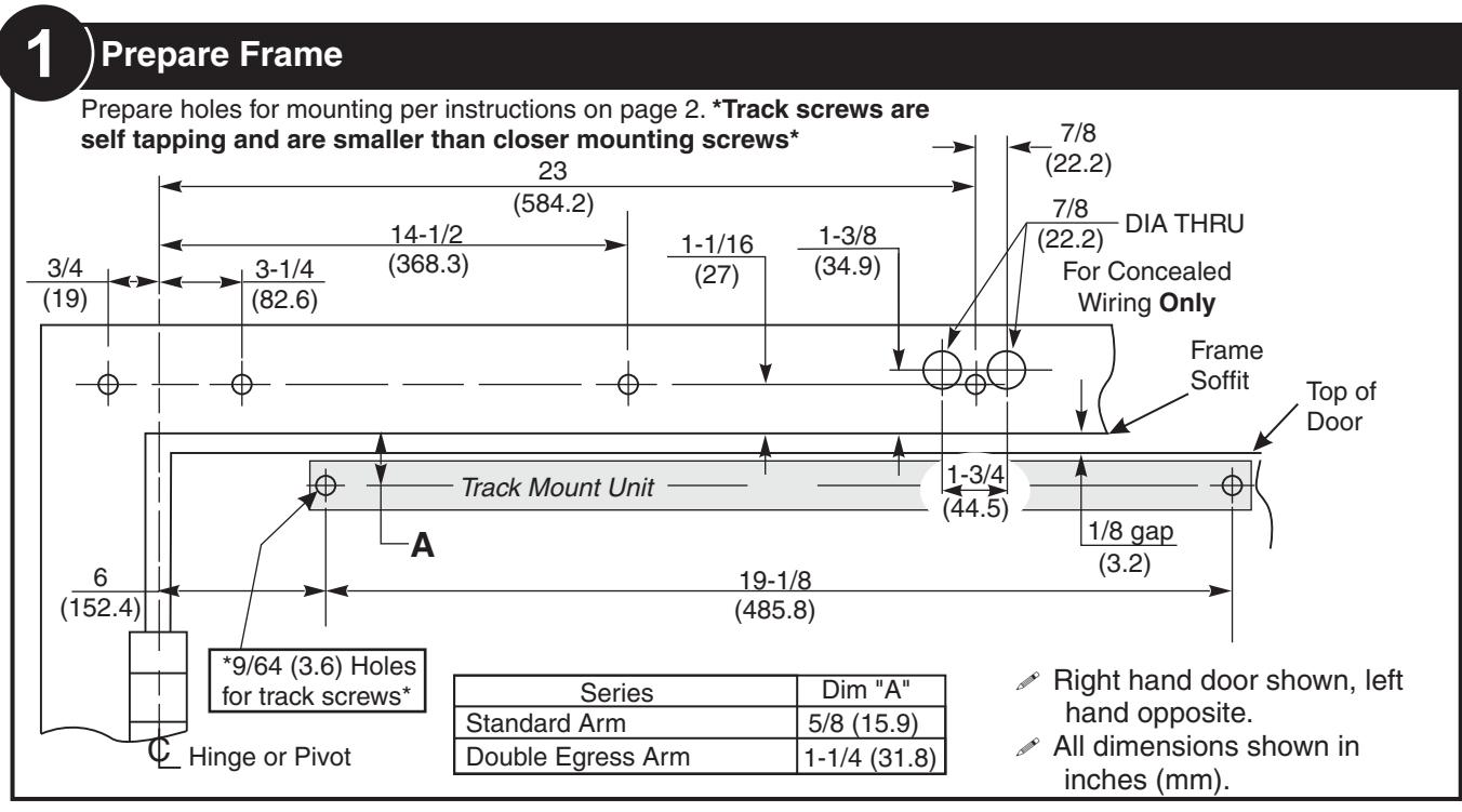
- All dimensions shown in inches (mm).
- Door must be hung on ball bearing butt hinges or 3/4" (19) offset pivots.
- Door thickness must be 1-3/4" (44) to 2-1/4" (64).
- Door must swing freely through the entire opening and closing cycle before beginning the installation procedure.
- Frame face must be a minimum of 2" (51).
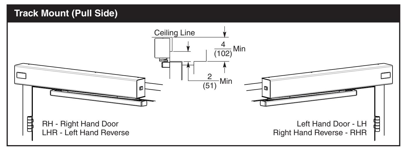
- Ceiling clearance must be a minimum of 3 -1/2" (89) for push side application or 4" (102) for pull side application. See pages 2 and 7 for templates.
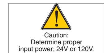
- Power input to unit must be of the same voltage as that stated on the unit.
- Unit to be mounted on interior of building in dry environment, maximum humidity of 95%.
- See NFPA70 for wiring requirements and NFPA72 for alarm system requirements.
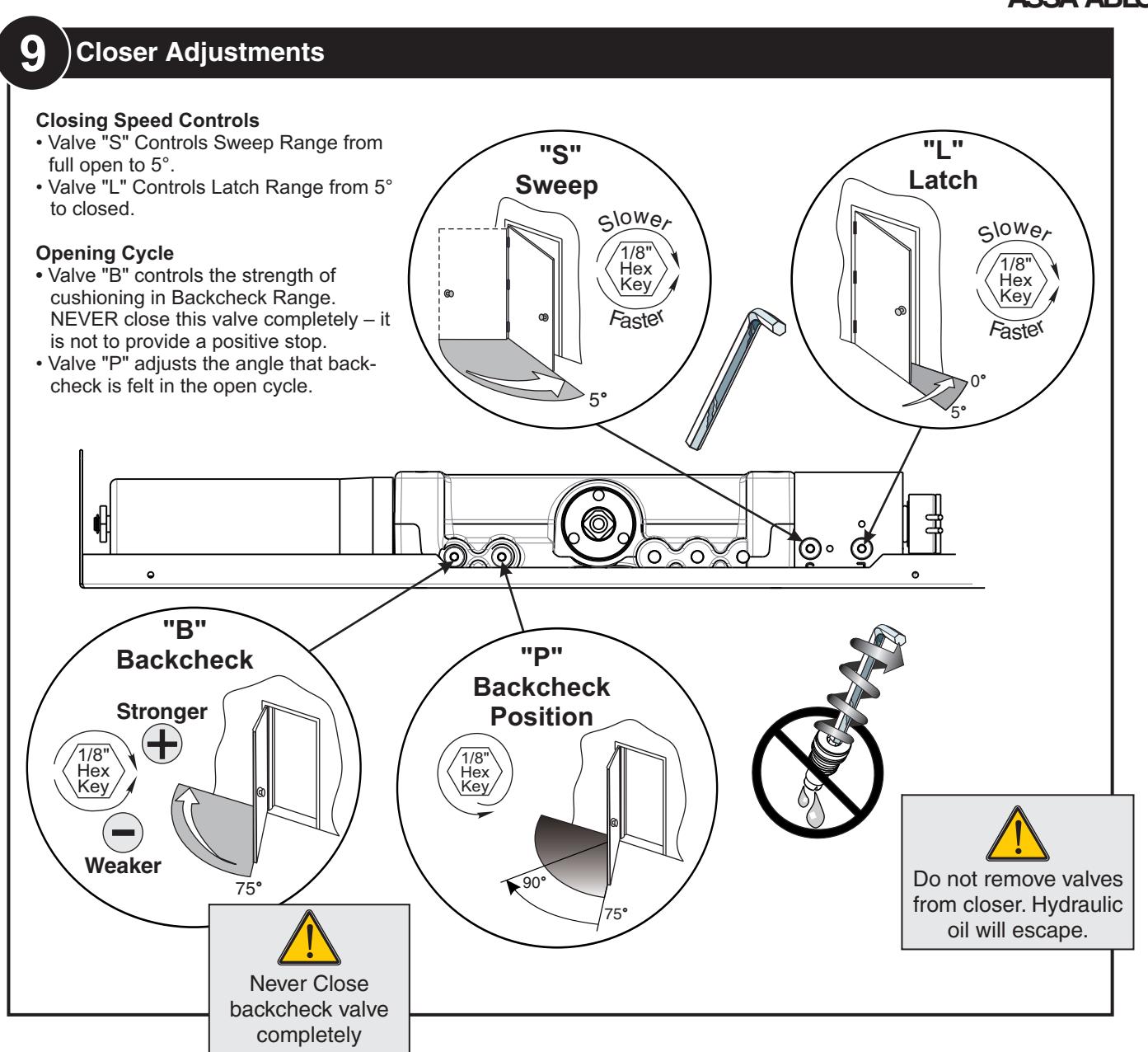
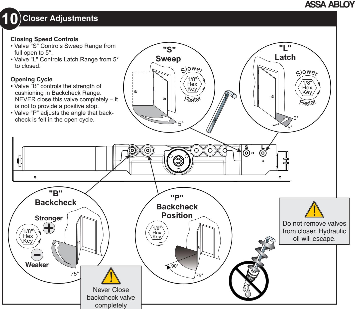
Closer Adjustments...................10 Hold Open Position Adj.............11 Non-Detectored Electrical.........12 Detectored Electrical.................13 RF Unit Electrical.................14-15 Troubleshooting.........................15 General Information..................16


10 Electrical Connections
See Page 13 for Non-Detectored Units See Page 14 for Detectored Units See Page 15 for RF Units

113 Selective Hold Open Cam Adjustment
Setting Hold Open Angle
- Make all required electrical connections and turn power switch to on for nondetectored units (detectored units cannot be turned off at the closer). (See previous step)
- Open door to desired hold open angle.
- Loosen cam screw and rotate cam until switch closes and door holds open.
- Rotate cam until it touches the switch.
- Tighten cam screw but do not over torque as this will cause damage to cam.

SHO switch in open position. Closer not in hold open.
SHO switch in closed position. Closer in hold open.
123 Attach Cover Attach cover using screws provided.

ASSA ABLOY

ASSA ABLOY

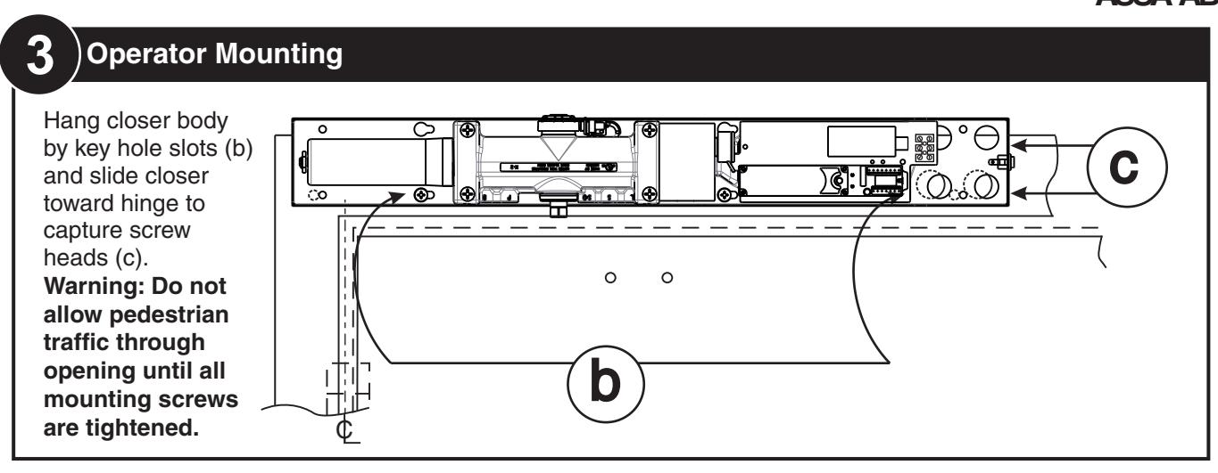
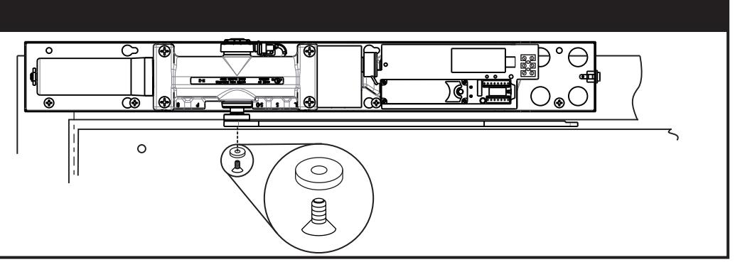
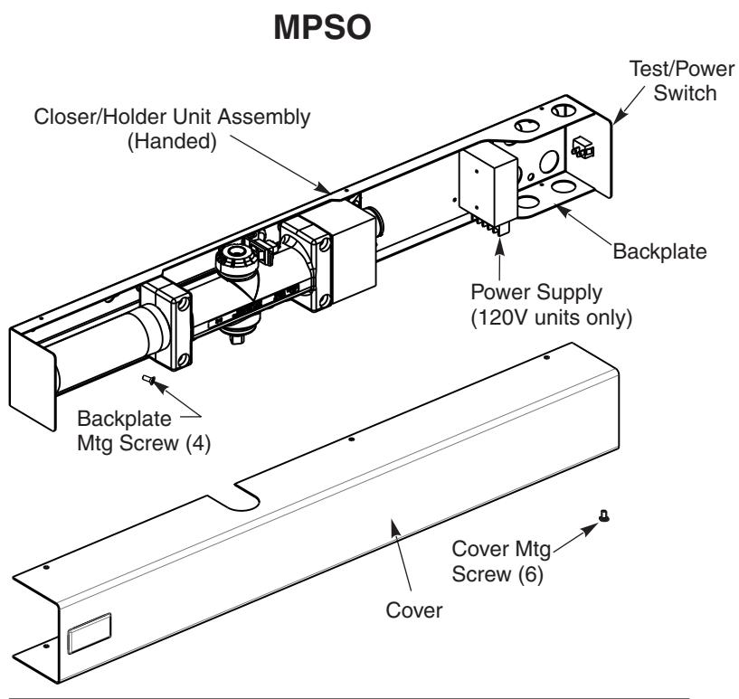
Hang closer body by key hole slots (b) and slide closer toward hinge to capture screw heads (c).
Warning: Do not allow pedestrian traffic through opening until all mounting screws are tightened.

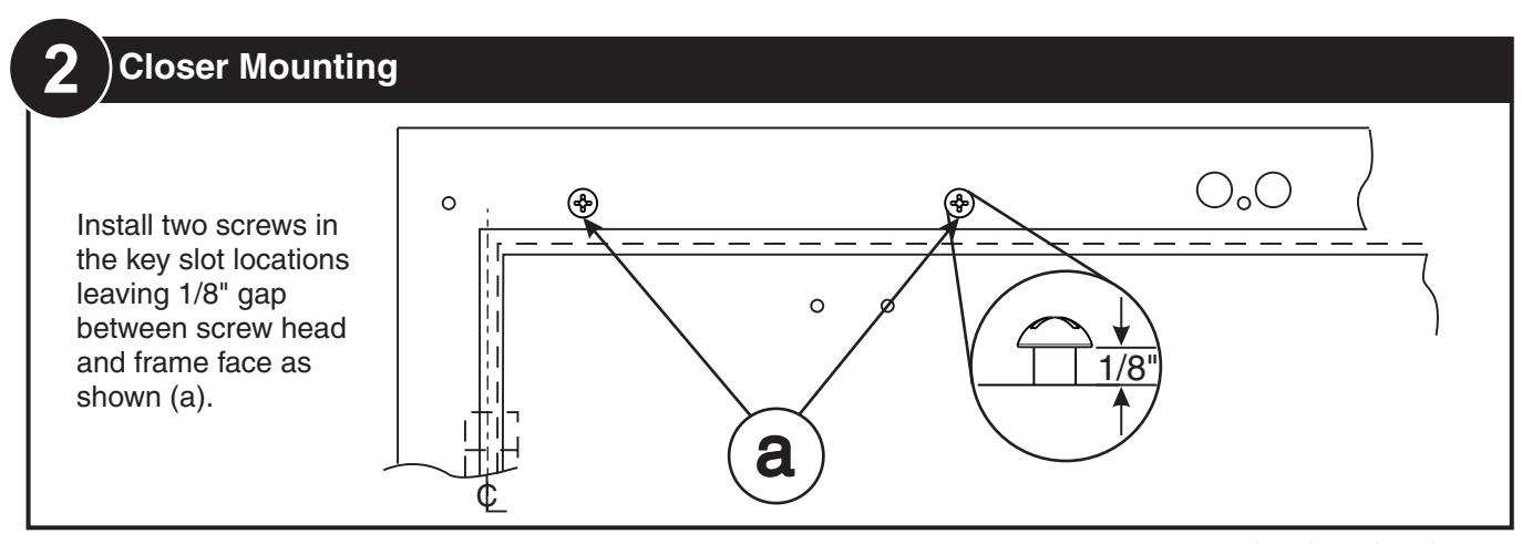
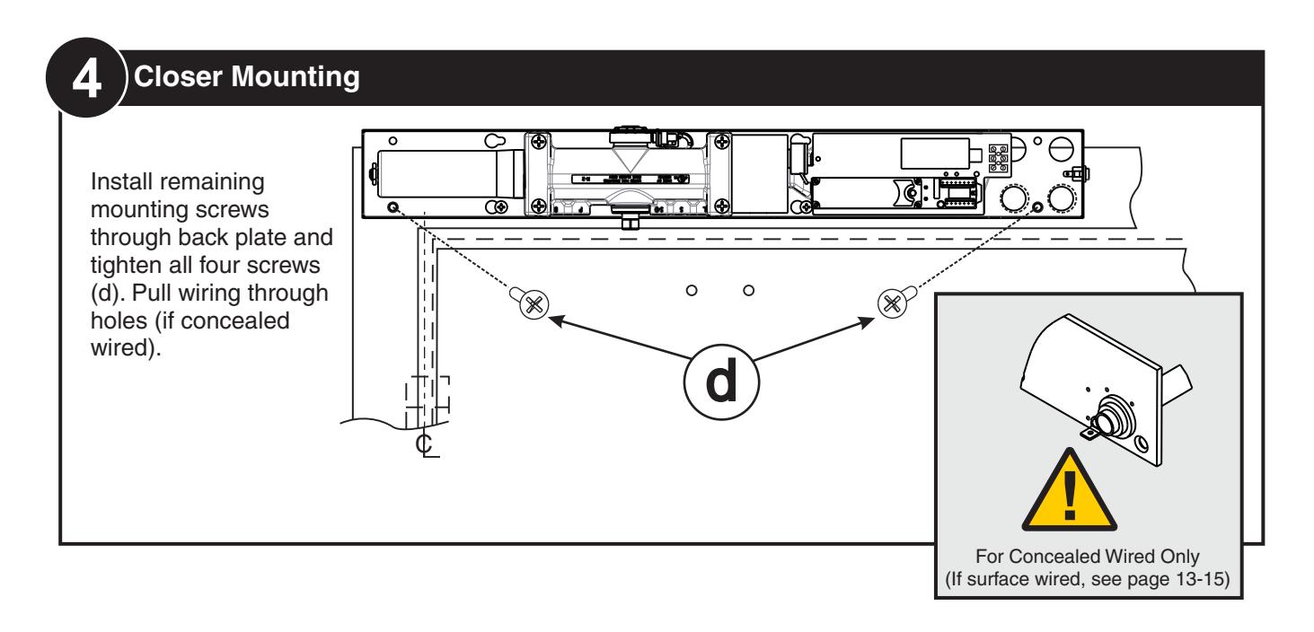
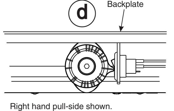
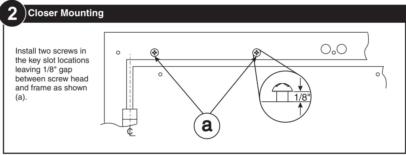
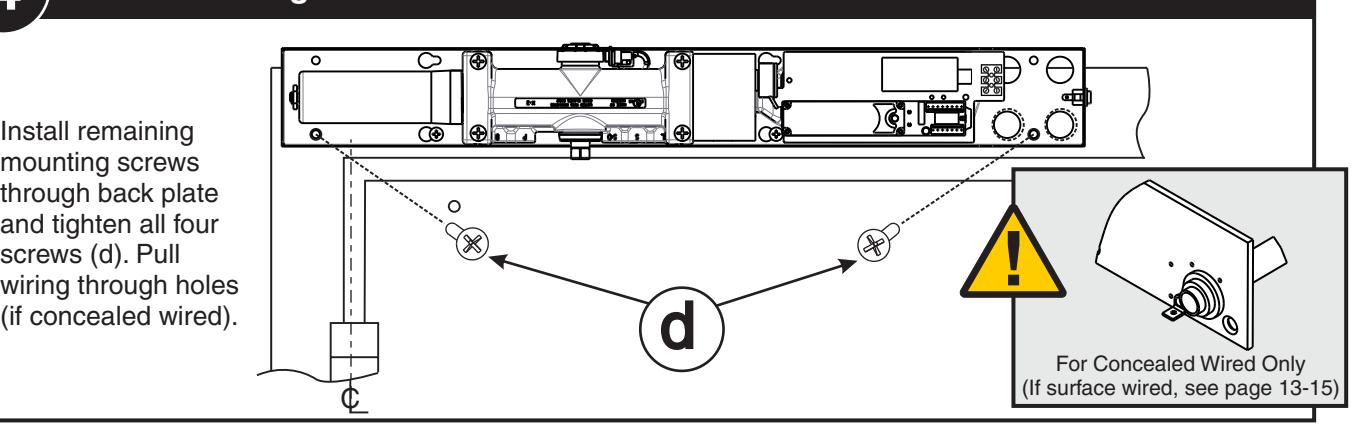
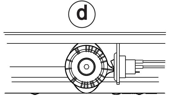
4 Closer Mounting
Install remaining mounting screws through back plate and tighten all four screws (d). Pull wiring through holes
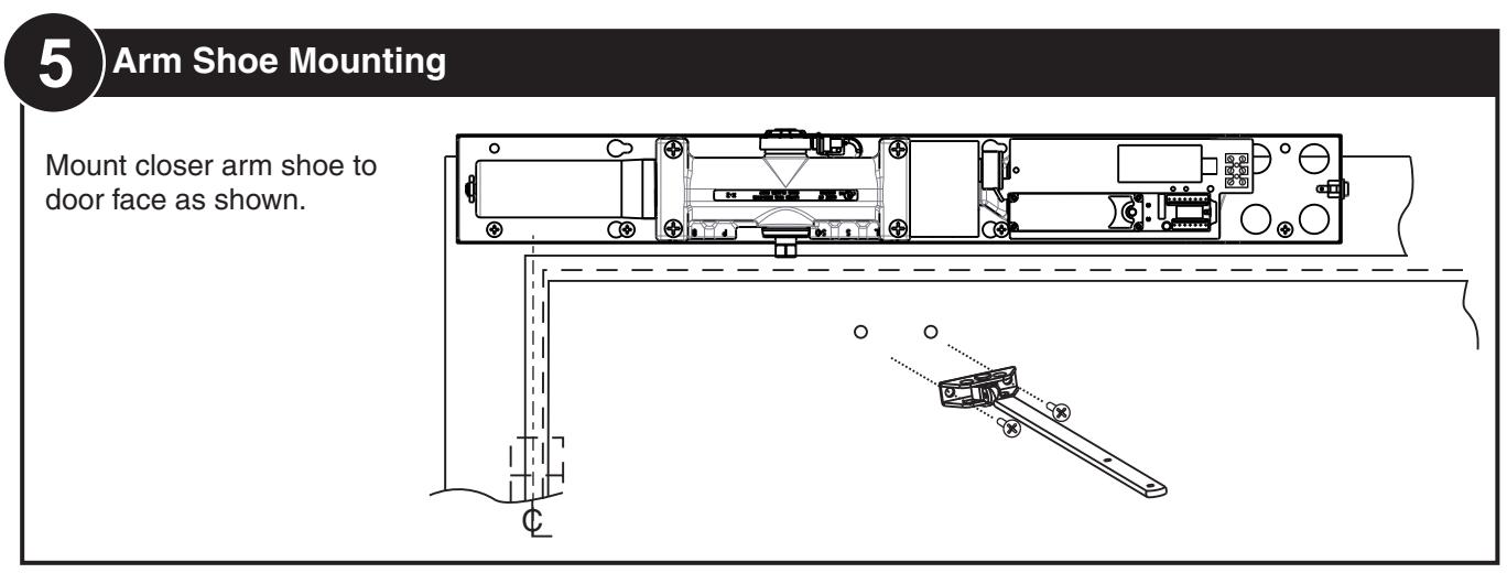
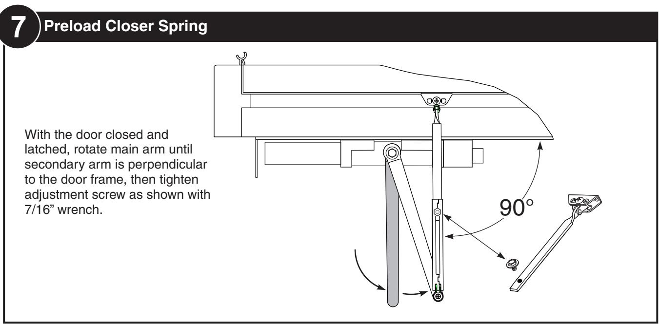
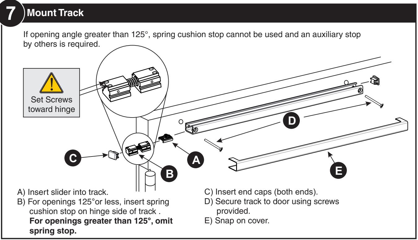
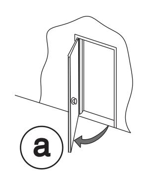
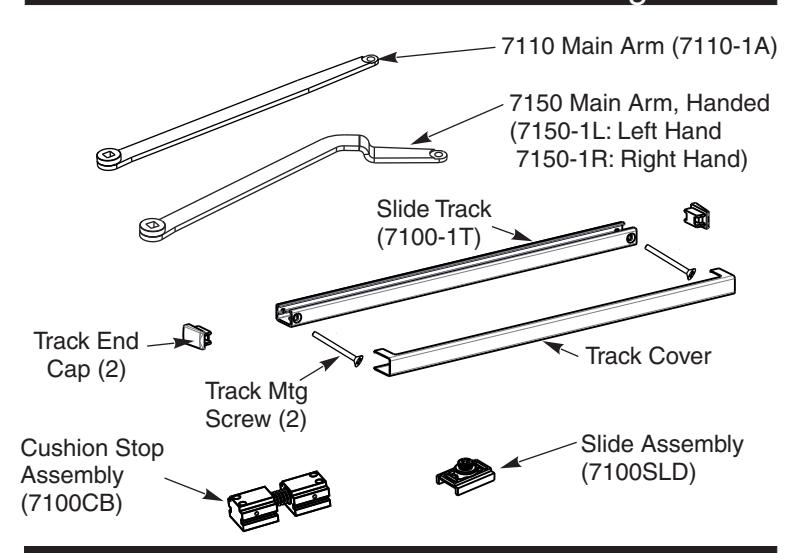
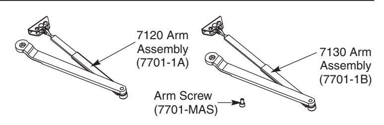
5 Arm Mounting
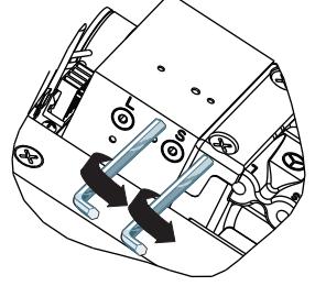
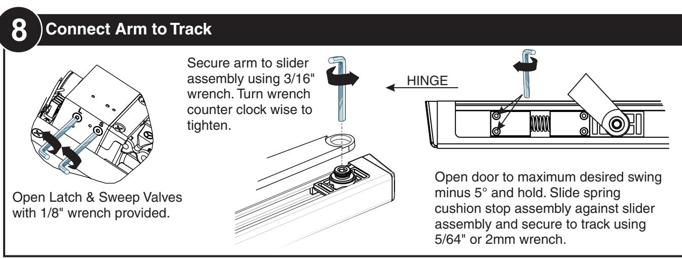
Fully close Latch & Sweep Valves with 1/8" wrench provided.
*All views from floor looking upward*
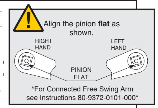
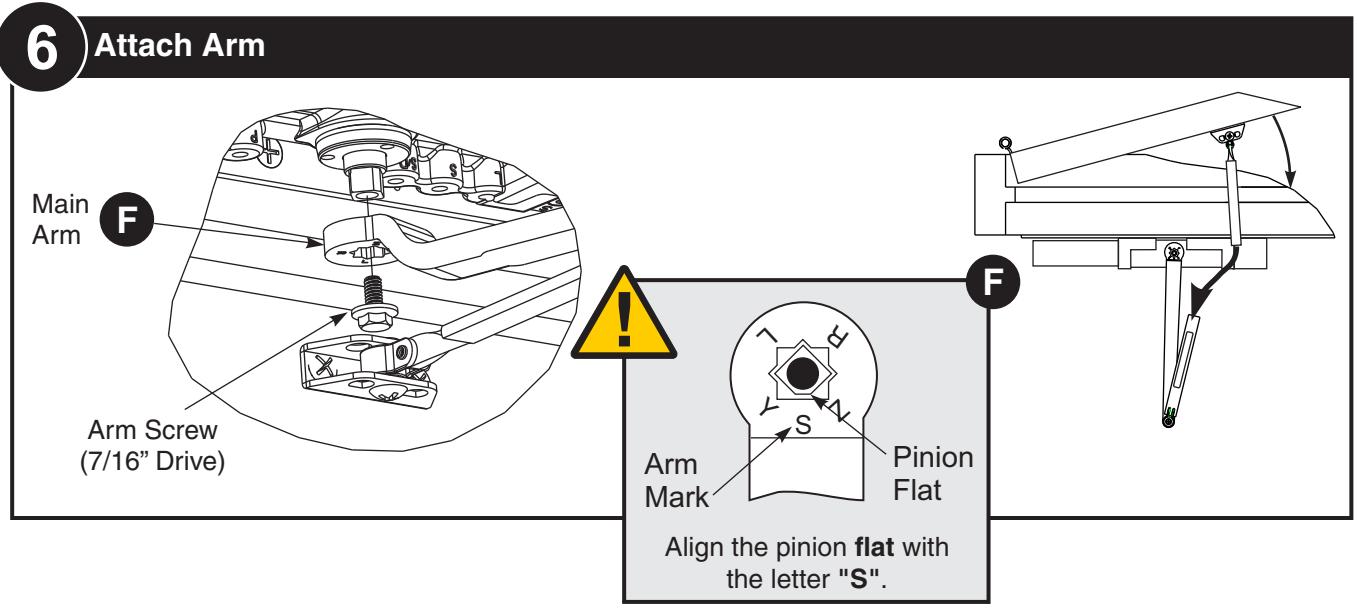
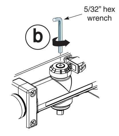
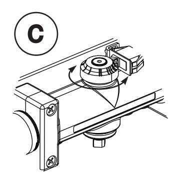
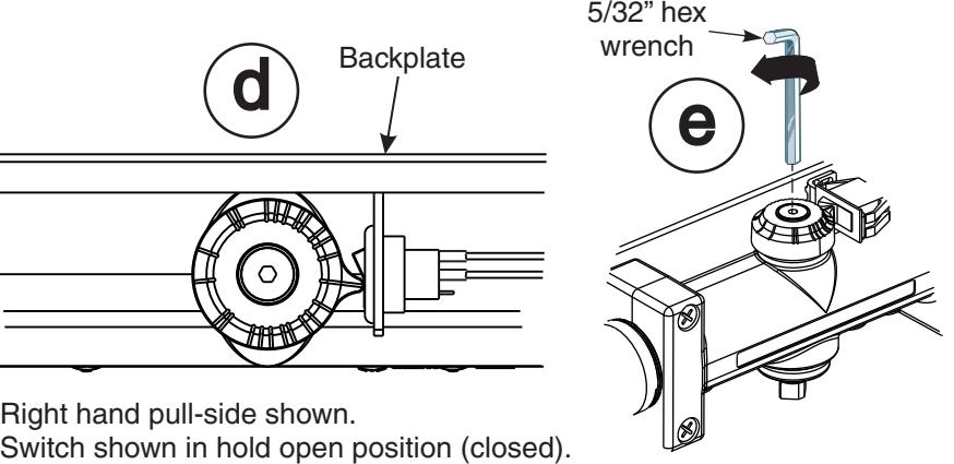
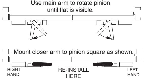
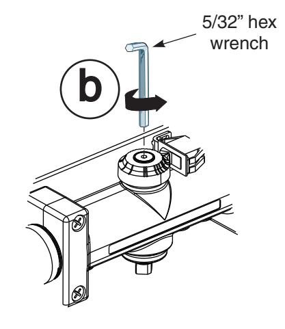
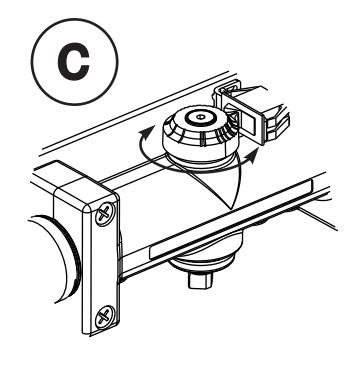
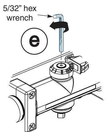
36 Attach Arm
Attach with provided screw and washer. Tighten arm screw with 5/32" hex wrench.


11 Electrical Connections
See Page 13 for Non-Detectored Units See Page 14 for Detectored Units See Page 15 for RF Units

123 Selective Hold Open Cam Adjustment
Setting Hold Open Angle
- Make all required electrical connections and turn power switch to "ON" for nondetectored units (Detectored units cannot be turned off at the closer).
- Open door to desired hold open angle.
- Loosen cam screw and rotate cam until switch closes and door holds open.
- Rotate cam until it touches the switch.
- Tighten cam screw but do not over torque as this will cause damage to cam.
- Force door out of hold open by closing the door, then test hold open by opening to hold open angle again.
SHO switch in open position. Closer not in
hold open.
Right hand pull-side shown.
Switch shown in hold open position.
SHO switch in closed position. Closer in hold open.
133 Attach Cover Attach cover using screws provided.

ASSA ABLOY
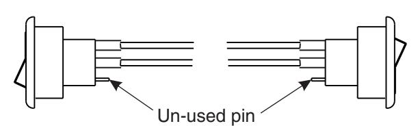
NON-DETECTORED ELECTRICAL CONNECTIONS
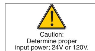
- Power input to unit must be of the same voltage as that listed on the label.
- All wiring connections use standard wiring practice conforming to local wiring codes.
- Maximum wire size is 18AWG.
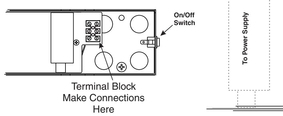
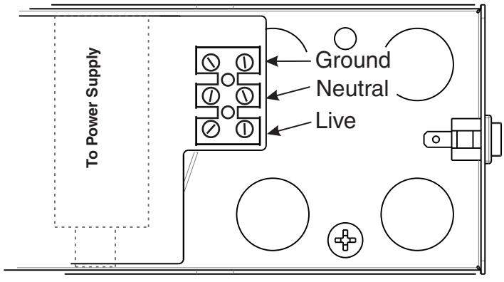
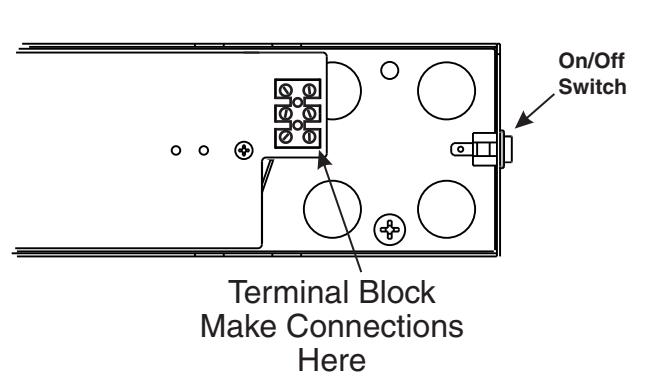
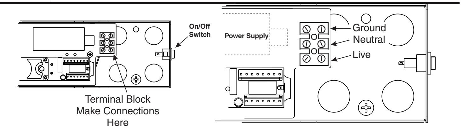
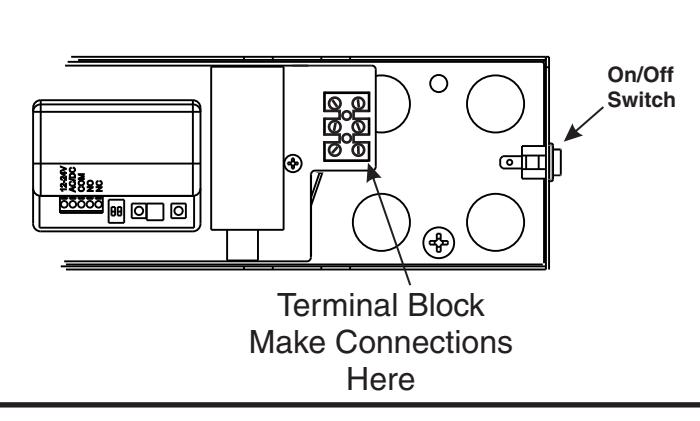
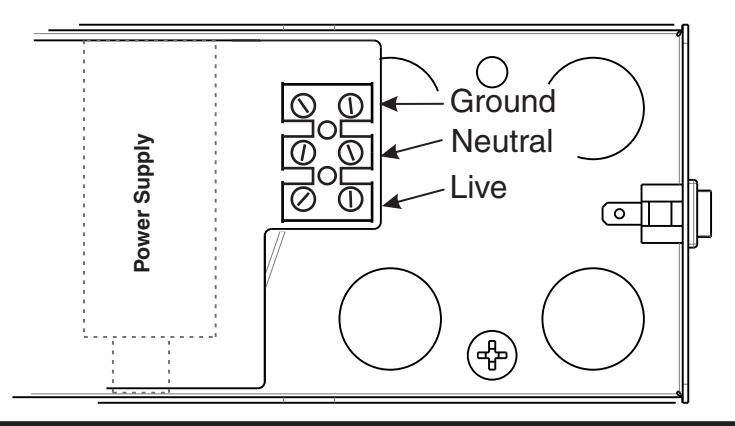
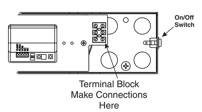
- Make input power connections to the terminal block or power supply using illustrations below.
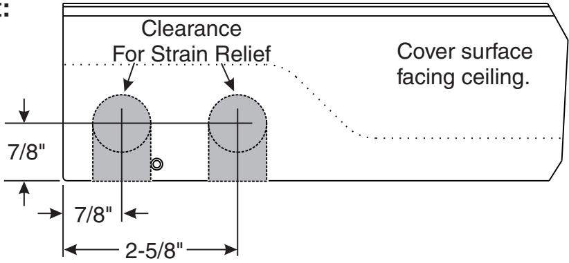
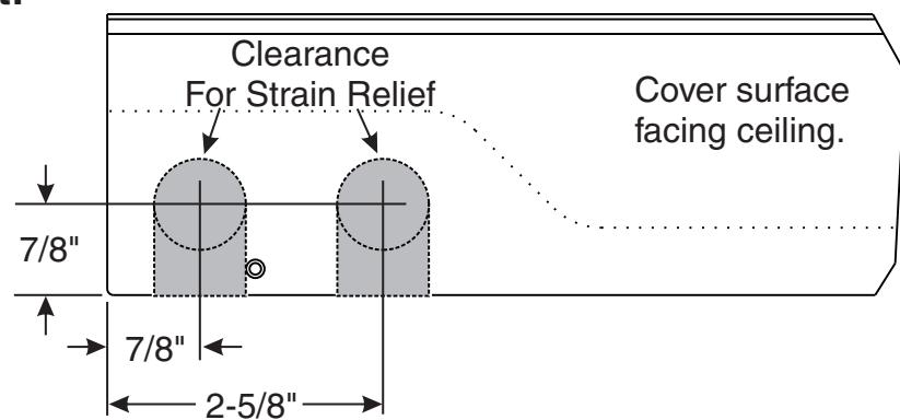
Surface mount power input:
Remove appropriate shaded area from cover for surface wired installations only. Repaint cut edges as necessary to prevent corrosion.

Stand-Alone wiring instructions below. (To incorporate other devices, see included wiring instruction manual: 80-9342-0904-000)
120V AC INPUT
Make power connections as shown below.
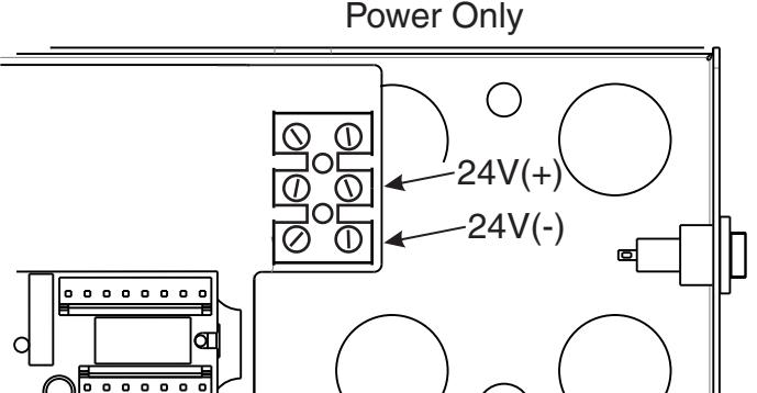
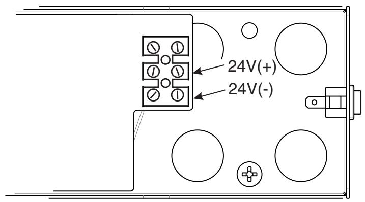
24V DC INPUT
Make power connections as shown below.


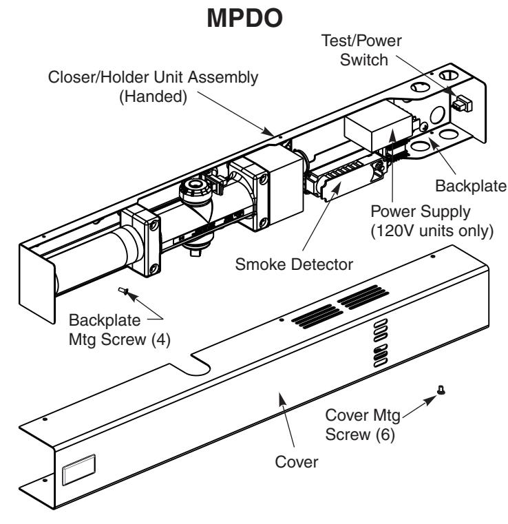
SMOKE DETECTOR ELECTRICAL CONNECTIONS

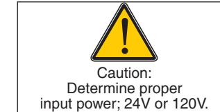
- Power input to unit must be of the same voltage as that listed on the label.
- All wiring connections use standard wiring practice conforming to local wiring codes.
- Maximum wire size is 18AWG.
- Make input power connections to the terminal block or power supply using illustrations below.
Surface mount power input:
Remove appropriate shaded area from cover for surface wired installations only. Repaint cut edges as necessary to prevent corrosion.
Stand-Alone wiring instructions below. (To incorporate other devices, see included wiring instruction manual: 80-9342-0904-000)
120V AC INPUT
Make power connections as shown below.
24V AC/DC INPUT
Make power connections as shown below.
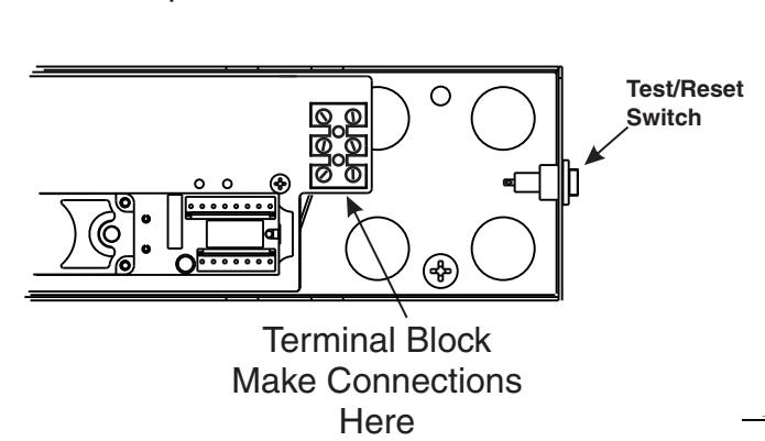
24VDC Input

RF REMOTE RECEIVER UNITS ELECTRICAL CONNECTIONS
- Power input to unit must be of the same voltage as that listed on the label.
- All wiring connections use standard wiring practice conforming to local wiring codes.
- Maximum wire size is 18AWG.
- Make input power connections to the terminal block or power supply using illustrations below.
Surface mount power input:
Remove appropriate shaded area from cover for surface wired installations only. Repaint cut edges as necessary to prevent corrosion.
120V AC INPUT
Make power connections as shown below.
24V AC/DC INPUT
Make power connections as shown below.
ASSA ABLOY, the global leader in door opening solutions

PROGRAMMING RF REMOTE RECEIVER UNITS
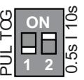
DIP SWITCH SETTINGS
| # 1 | DESCRIPTION | FUNCTION |
|---|---|---|
| OFF | Pulse Relay | Press the transmitter once and the relay will be active momentarily. |
| ON | Toggle Relay | Press the transmitter once and the relay output is active indefinitely, press it again and the relay will de-energize indefinitely. |
| PUL TOG | 5s | 10s |
|---|---|
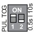
In Toggle Setting (1-ON), the Hold Time is inactive. Either setting for #2 dip switch will have the same result.
| #2 | DESCRIPTION | FUNCTION (Pulse Mode Only) | |
|---|---|---|---|
| OFF | 0.5 sec Hold Time | Relay will remain active 0.5 second after the loss of activation. | |
| ON | 10 sec Hold Time | Relay will remain active 10 seconds after the loss of activation. | |
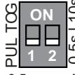
0.5 second Pulse Setting
DIE
Pulse Setting
RED LED
LEARN W/O DELAY
BUTTON
HAND HELD CONFIGURATION
- 1. Set dip switches on the receiver to the desired activation cycle (dip switch 1 -Toggle or Pulse and dip switch 2 0.5s or 10s hold).
- Press either Learn w/Delay Button or Learn w/No Delay Button on the receiver depending on the activation requirements (If delay learn is selected, adjust potentiometer to counterclockwise limit, 0 second delay). After learn cycle is complete, adjust potentiometer to desired delay time (0-30 sec).
- 3. Depress transmitter button repeatedly until Blue LED on the receiver illuminates (indicating reception of signal from transmitter).
NOTE: Repeat Steps 2-3 to program additional transmitters.
4. To test the system, depress transmitter button (Red LED on Transmitter will illuminate) and observe that the Blue LED illuminates on the receiver. This indicates that the relay has been activated. ANTENNA WIRE
PUSH PLATE CONFIGURATION
- 1. Before beginning, it is easiest to have already prepared the installation of the pushplate.
- 2. Connect the wires from the transmitter to the NO and COM contacts of the pushplates switch.
- Follow Steps 1-4 (Hand-Held Configuration); depress the pushplate to activate the transmitter.
Attach the transmitter to the inside of the electrical box and complete the installation. REMOVING TRANSMITTER CODE(S) SINGLE TRANSMITTER CODE

2. Press transmitter button twice within 10 seconds and the transmitter code will be deleted.
ALL TRANSMITTER CODES
1. Press and hold both DELAY and NO DELAY BUTTONS simultaneously until Blue LED illuminates then release (approximately 10 seconds)
Troubleshooting
DETECTORED AND NON-DETECTORED UNITS
| SYMPTOMS | PROBABLE CAUSE | CORRECTIVE ACTION | |
|---|---|---|---|
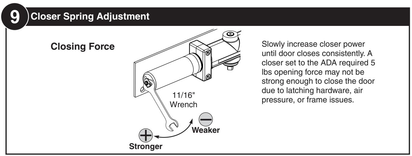
| Door does not hold open. | No power to unit. Loose wire connection. Cam switch not engaged. | Check input voltage: 24VDC or 120VAC Inspect wiring for loose connections. Adjust Cam position (see pg. 6 or 11) | |
| Door holds open but at the wrong angle. |
Cam switch engaged too early or too late.
Cam switch shorted. |
Adjust Cam position (see pg. 6 or 11) Inspect Cam switch wiring for short circuit. | |
| Door not closing when Test/Reset switch depressed. (Detectored units only) | Wiring incorrect. Short circuit across Test/Reset switch. | Inspect wiring (see pg.13-15). Inspect Test/Reset switch for short circuit. | |
RF UNITS
| SYMPTOMS | PROBABLE CAUSE | CORRECTIVE ACTION |
|---|---|---|
| Red LED flashes on RF unit and can't program receiver. | Push plate stuck or faulty transmitter. | Disconnect each push plate or remove batteries until LED goes out. Replace faulty push plate. |
| Receiver intermittently doesn't receive the transmitter signal. | Receiver antenna wire is too short | Add 6 3/4' lengths of wire to antenna until it receives signal. |
For problems not listed here, see page 16 for Technical Product Support Contact info.
General Information
Included with Pull Side or Double Egress
Included with Push Side
Certifications
UL228, UL10B
| Preparation for Fasteners | ||||
|---|---|---|---|---|
|
Door or Frame
Fasteners Drill-Sizes |
||||
|
1/4" - 20 machine
screw |
Metal |
Drill: #7 (0.201" dia.)
Tap: 1/4" - 20 |
||
|
Self tapping screw
(Track screws only) |
Metal /
Wood |
Pre-Drill: 9/64 hole | ||
| Standard |
Self tapping screw
(Closer mounting screws only) |
Metal /
Wood |
Pre-Drill: 3/16 hole | |
|
Sleeve nuts and
bolts (Shoe screws only) |
Hollow
Metal |
9/32" (7 mm) through;
3/8" (9.5 mm) door face opposite to closer |
||
|
Aluminum
or Wood |
3/8" (9.5 mm) through | |||
| Optional |
Through-bolts and
grommet-nuts |
All |
9/32" (7 mm) thru;
3/8" (9.5 mm) dia. x 3/8" (9.5 mm) deep on door opposite to closer |
|

ASSA ABLOY
3000 Highway 74 East • Monroe, NC 28112 Tel: (877)- • Fax: (800)-338-0965 974-2255 www.nortondoorcontrols.com