Norton Rixson 7100SZ Series Door Closer, SafeZone, Selective Hold Open Option Installation Instructions_80-9371-0085-020
Open the original PDF document
View PDF

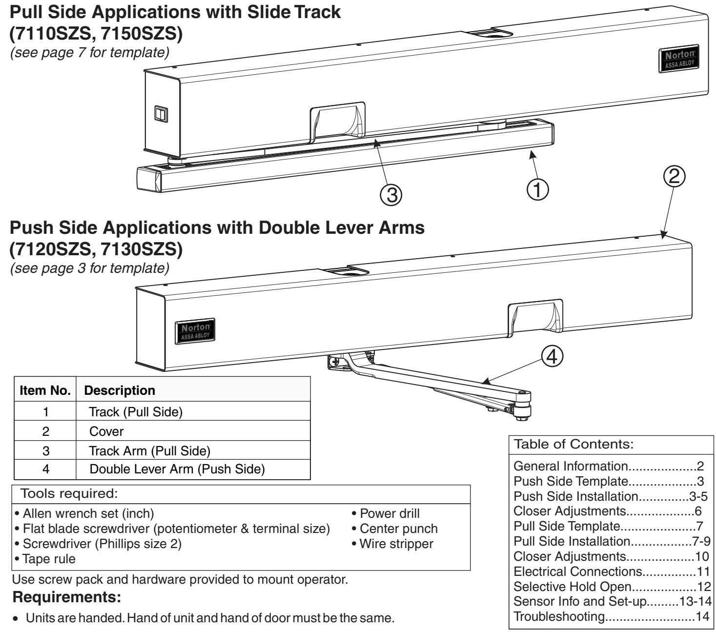
7100SZ Series SafeZone® With Selective Hold Open Option Installation and Instruction Manual
ASSA ABLOY
Patent Pending
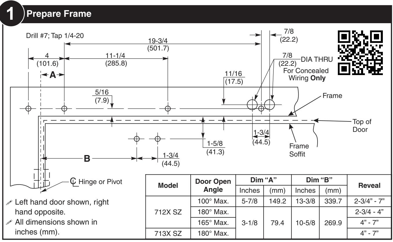
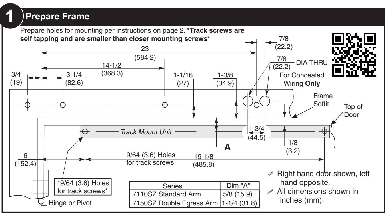
- All dimensions shown in inches (mm).
- Door must be hung on ball bearing butt hinges or 3/4" (19) offset pivots.
- Door thickness must be 1-3/4" (44) to 2-1/4" (64).
- Door must swing freely through the entire opening and closing cycle before beginning the installation procedure.
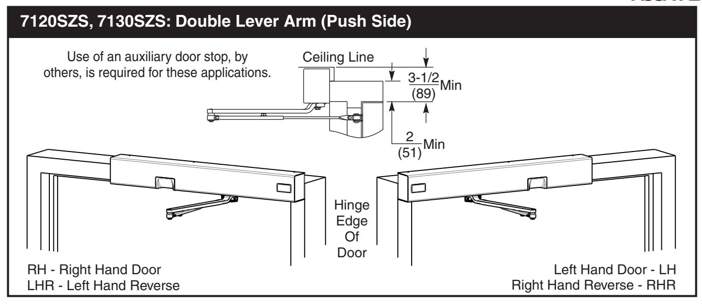
- Frame face must be a minimum of 2" (51).
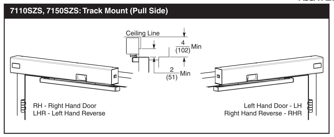
- Ceiling clearance must be a minimum of 3 -1/2" (89) for push side application or 4" (102) for pull side application. See pages 3 and 7 for templates.
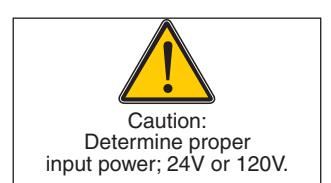
- Power input to unit must be of the same voltage as that stated on the unit.
- Unit to be mounted on interior of building in dry environment, maximum humidity of 95%.
- See NFPA70 for wiring requirements and NFPA72 for alarm system requirements.

General Information
| Preparation for Fasteners | |||||
|---|---|---|---|---|---|
|
Door or Frame
Drill-Sizes Fasteners |
|||||
| Standard |
1/4" - 20 machine
screw |
Metal |
Drill: #7 (0.201" dia.)
Tap: 1/4" - 20 |
||
|
Self drilling screw
(Track screws only) |
Metal | Pre-Drill: 9/64 hole | |||
|
Self drilling screw
(Closer mounting screws only) |
Metal | Pre-Drill: 3/16 hole | |||
|
Sleeve nuts and
bolts (Shoe screws only) |
Hollow
Metal |
9/32" (7 mm) through;
3/8" (9.5 mm) door face opposite to closer |
|||
|
Aluminum
or Wood |
3/8" (9.5 mm) through | ||||
| Optional |
Through-bolts and
grommet-nuts |
All |
9/32" (7 mm) thru;
3/8" (9.5 mm) dia. x 3/8" (9.5 mm) deep on door opposite to closer |
||
Certifications
UL228, UL10B

ASSA ABLOY


ASSA ABLOY
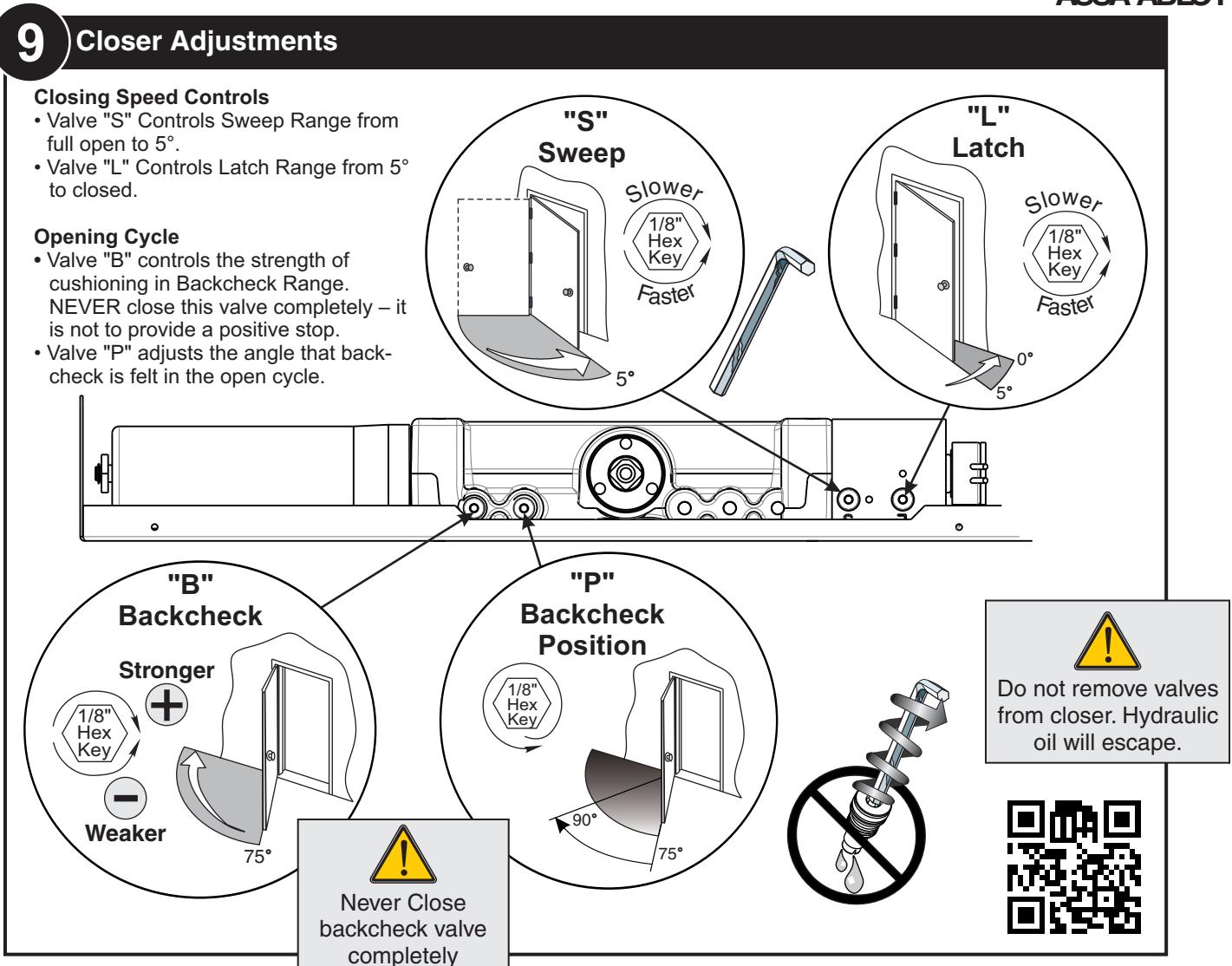
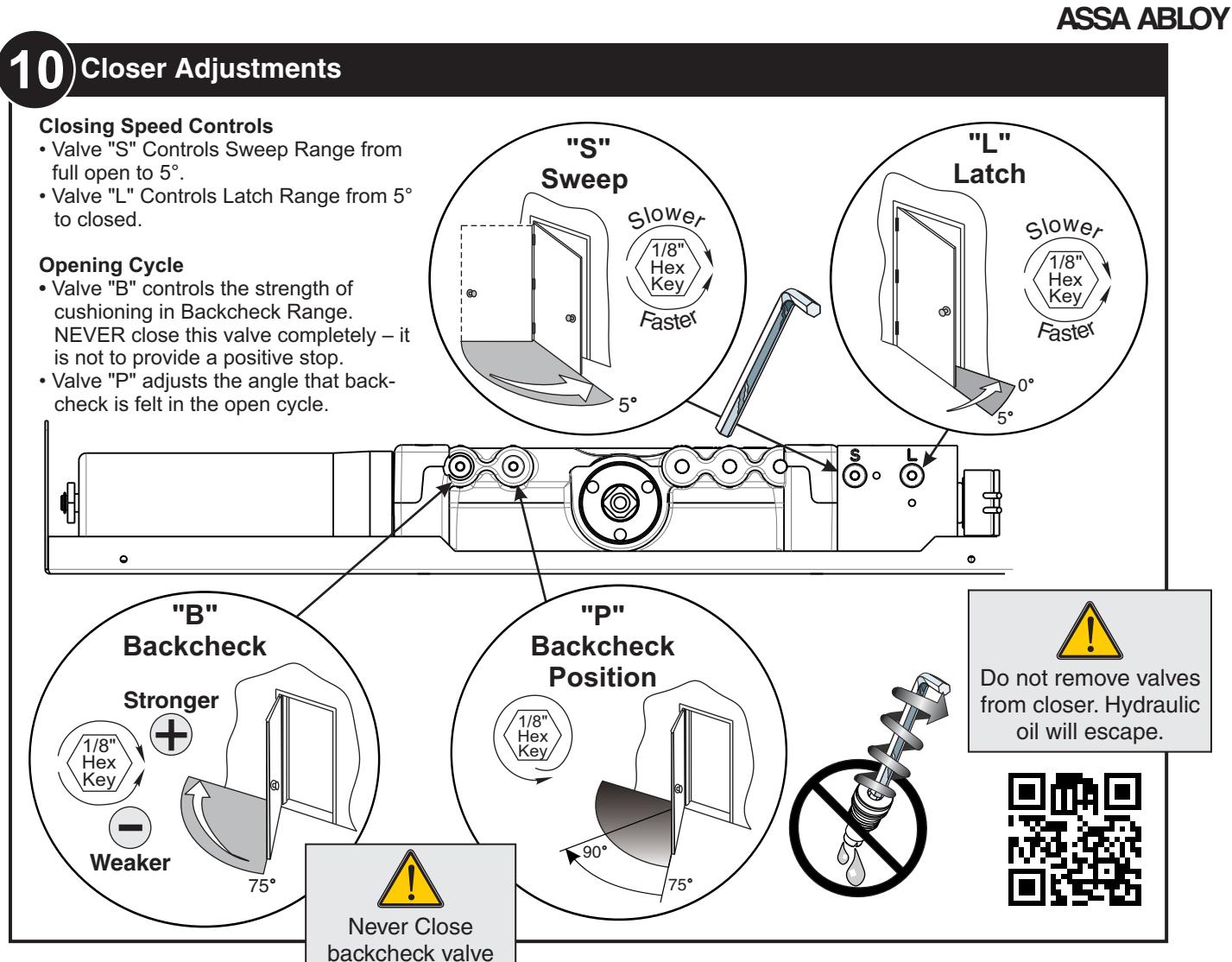
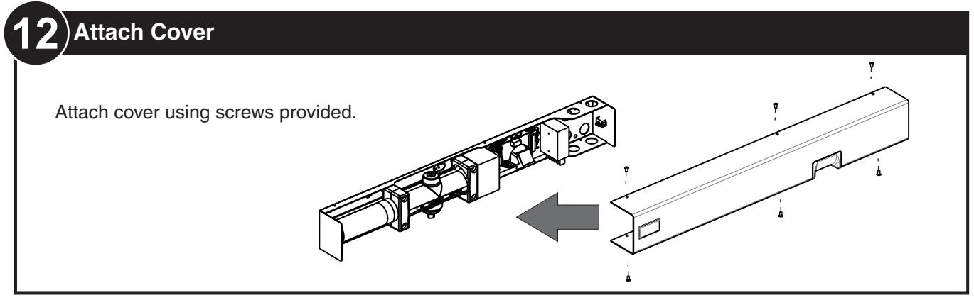
10) Electrical Connections / Selective Hold Open Adjustments
Electrical Connections — Page 11 Selective Hold Open Adjustments—Page 12

80-9371-0085-020 Rev 3 (05-24)


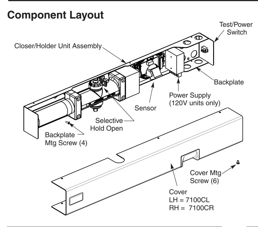
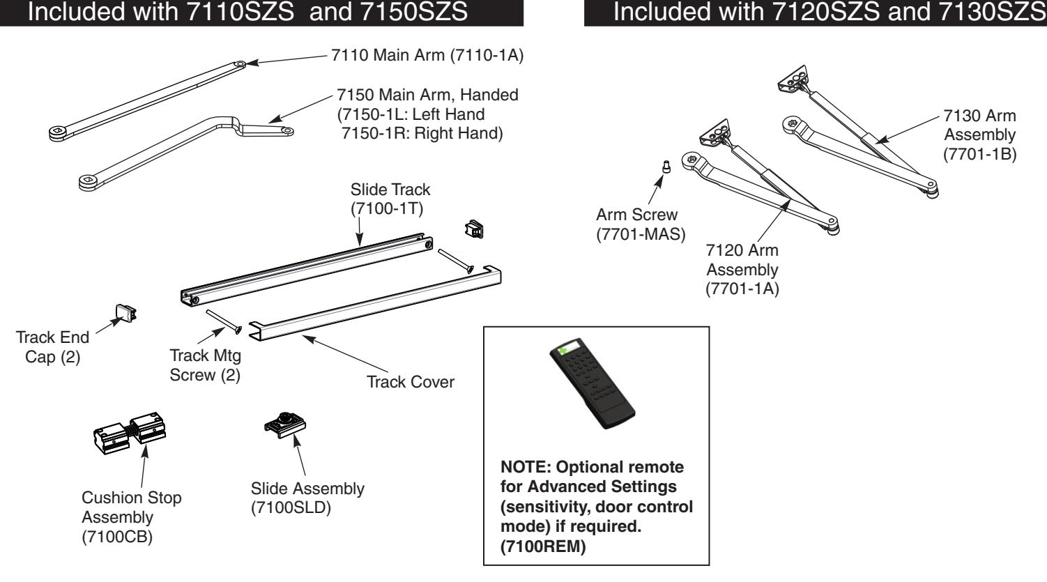
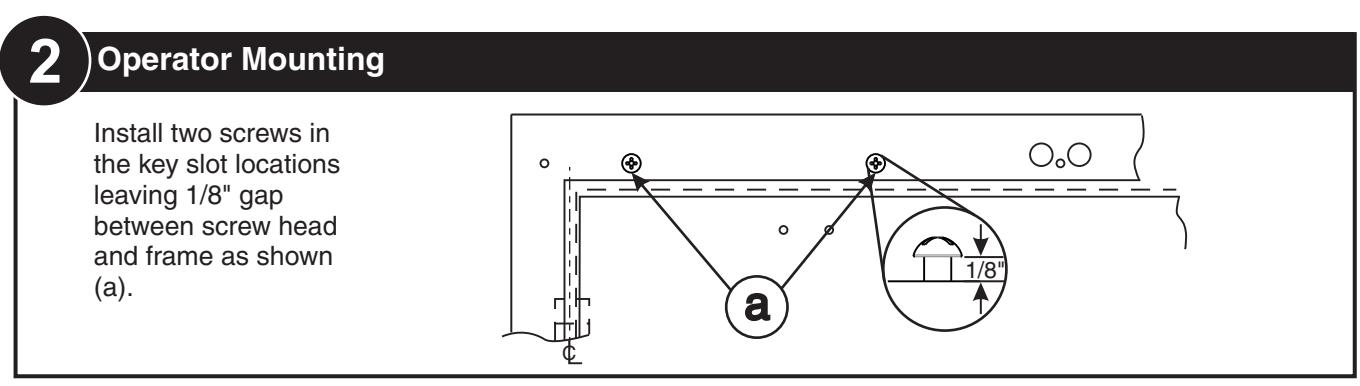
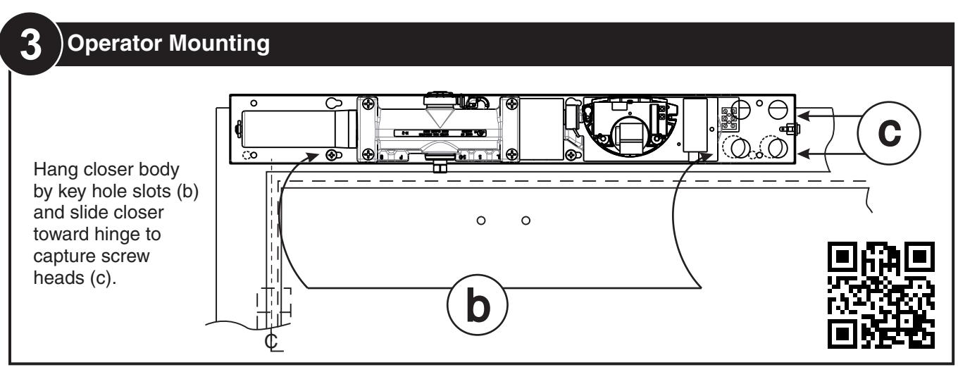
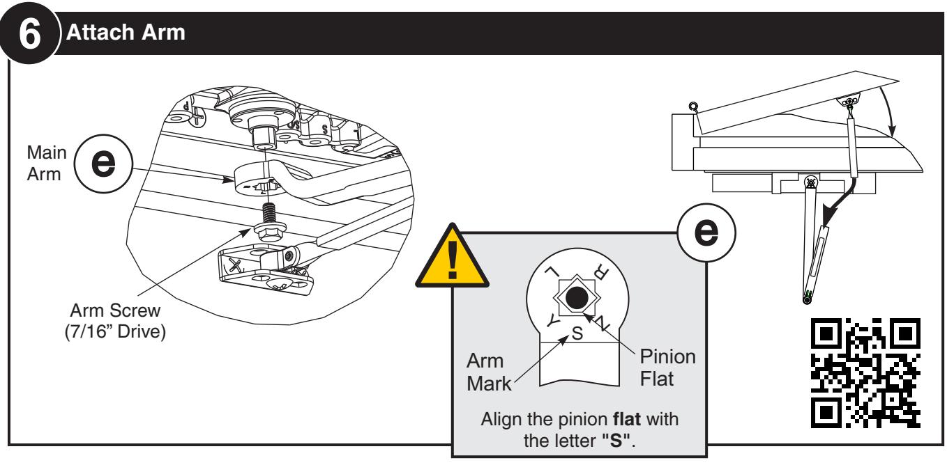
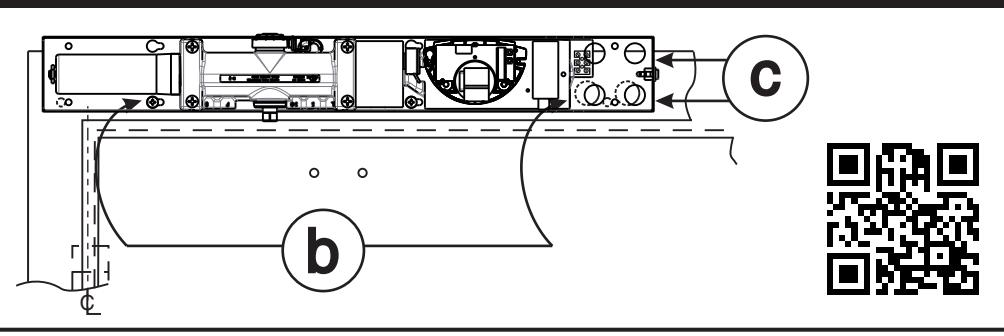
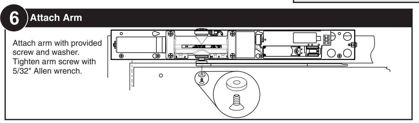
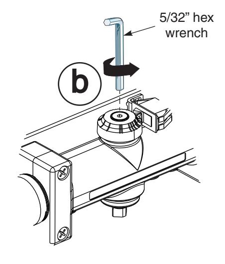
Hang closer body by key hole slots (b) and slide closer toward hinge to capture screw heads (c).
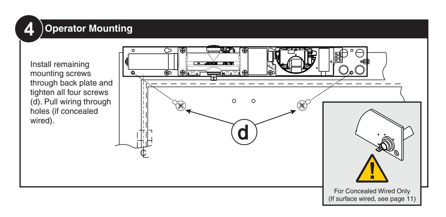
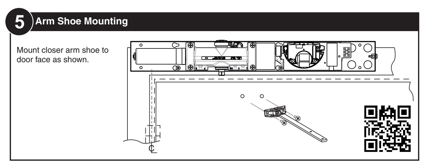
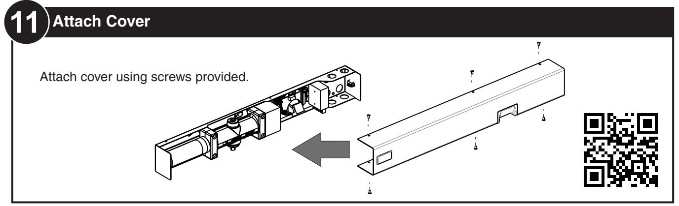
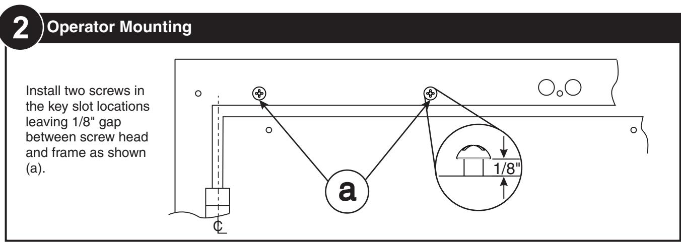
4 Operator Mounting
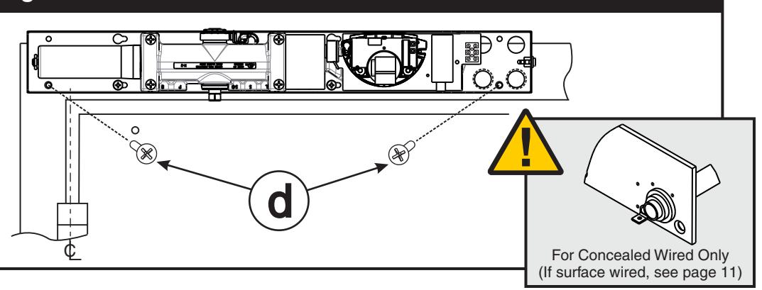
Install remaining mounting screws through back plate and tighten all four screws (d). Pull wiring through holes (if concealed wired).


If opening angle greater than 125°, spring cushion stop cannot be used and an auxiliary stop
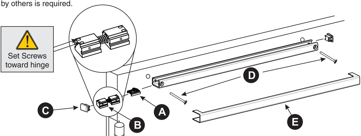
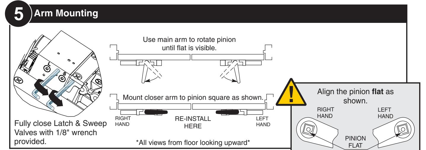
- 1) Insert slider into track.
- 2) Insert spring cushion stop on hinge side of track for 125°or less opening angle. !Do not use for openings greater than 125°!
- 3) Insert end caps (both ends).
- 4) Secure track to door using provided screws.
- 5) Snap on cover.


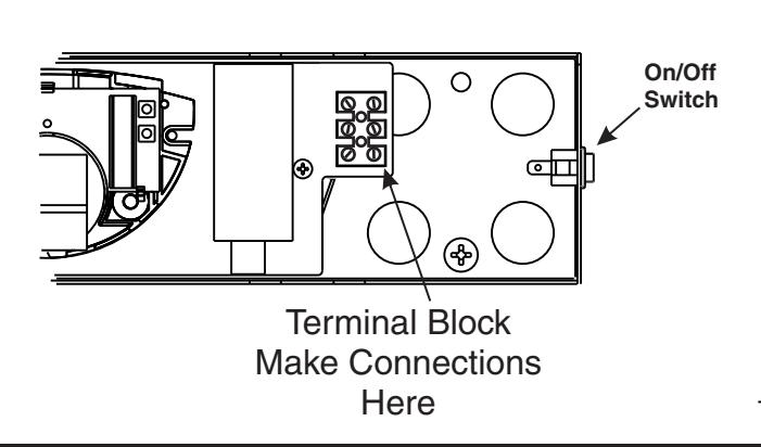
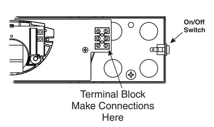
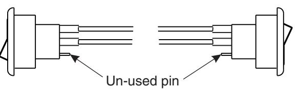
11 Electrical Connections
Electrical Connections — Page 11 Selective Hold Open Adjustments—Page 12
completely

ELECTRICAL CONNECTIONS
- Power input to unit must be of the same voltage as that listed on the label.
- All wiring connections use standard wiring practice conforming to local wiring codes.
- Maximum wire size is 18AWG.
- Make input power connections to the terminal block or power supply using illustrations.
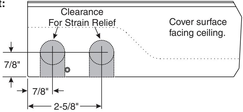
Surface mount power input:
Remove appropriate shaded area from cover for surface wired installations only. Repaint cut edges as necessary to prevent corrosion.
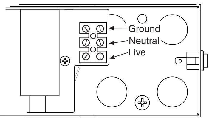
120V AC INPUT
Make power connections as shown below.
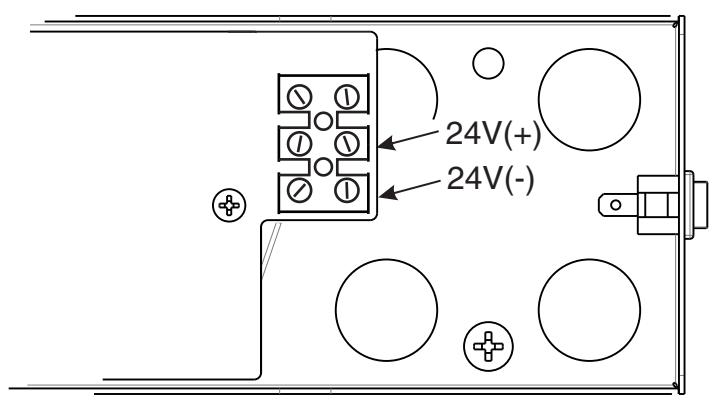
24V DC INPUT
Make power connections as shown below.

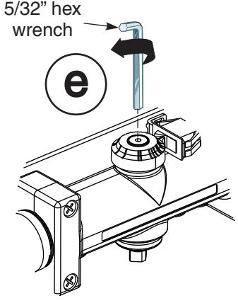
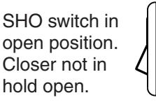
SELECTIVE HOLD OPEN ADJUSTMENT
Setting Hold Open Angle
- Make all required electrical connections and turn power switch to "ON" for nondetectored units (Detectored units cannot be turned off at the closer).
- Open door to desired hold open angle.
- Loosen cam screw and rotate cam until switch closes and door holds open.
- Rotate cam until it touches the switch.
- Tighten cam screw but do not over torque as this will cause damage to cam.
- Force door out of hold open by closing the door, then test hold open by opening to hold open angle again.
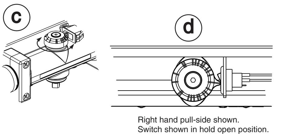
SHO switch in closed position. Closer in hold open.


Sensor Technical Specifications
| DESCRIPTION | SPECIFICATION | |
|---|---|---|
| Frequency: | 24.125 GHz | |
| Supply voltage: | 12 t 24 V DC: -10% / +30%: | |
| Mounting height: | Normal: 7'; Maximum: 10'-0" | |
| Tilt angle: | 0° to 90° vertical | |
| -15° to +15° lateral | ||
| Detection area: | ||
| Wide | 13ft (W) x 6.5ft (D) | |
| Narrow | 6.5ft (W) x 8.2ft (D) (supplied as optional) | |
| Minimum detection speed: | 2 in/sec. (measured in axis) | |
| Power consumption: | < 2 W | |
| Standard output relay: | ||
| Max contact voltage | 60 VDC / 125 VAC | |
| Max contact current | 1 A (resistive) | |
| Max switching power | 30W (DC) / 60VA (AC) | |
| Hold time: | 0.5 sec. to 9 sec. (adjustable) | |
| Temperature range: | -4°F to 131°F | |
| Dimensions: | 4.75in (W) x 3.15in (H) x 2.0in (D) | |
| Weight: | 0.5lbs | |
| Material: | ABS | |
Safety Precautions
- Shut off all power going to the header before attempting any wiring procedures.
- Maintain a clean & safe environment when working in public areas.
- Constantly be aware of pedestrian traffic around the door area.
- Always stop pedestrian traffic through the doorway when performing tests that may result in unexpected reactions by the door.
- Always check placement of all wiring and components before powering up to ensure that moving door parts will not catch any wires and cause damage to equipment.
- Ensure compliance with all applicable safety standards upon completion of installation.
ELECTROSTATIC DISCHARGE (ESD) PRECAUTIONS
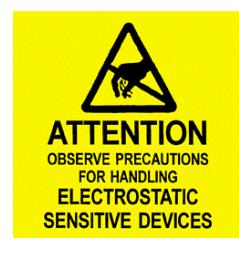
Circuit board components are vulnerable to damage by electrostatic discharge (ESD). ESD can cause immediate or subtle damage to sensitive electronic parts. An electrostatic charge can build up on the human body and then discharge when you touch a board. A discharge can be produced when walking across a carpet and touching a board, for example. Before handling any board, make sure you dissipate your body's charge.
CAUTION: In the event a unit needs to be opened, observe the following precautions.
- Ground yourself by touching a conductive surface of the door or other element connected to common earth ground to discharge the static electricity present in your body.
- Avoid walking around while replacing items inside the case, especially if you are on carpet or during conditions of low temperature and low humidity.
- Handle the board by the edges only to avoid touching electronic components.
- Store a loose board in an anti-static bag.
Sensing Field Adjustments
THE OSITI P ON OF THE NSING FIELD IS SE DETERMINE THE VERTIC D BY AL AND LATERAL ANGLE OF THE ANTENNA
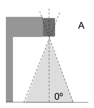
0º 30º A B
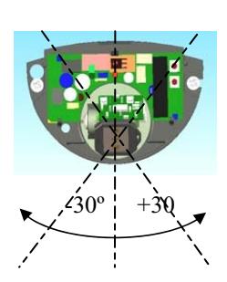
Sensing field as close to the dooras possible: -antenna set at the position of 0°
Sensing field close to the door: -antenna set at the position of 30°
Sensing field far from the door: -antenna set at the position of 45°
Hold Time Settings
Hold open time refers to the time the door will remain open AFTER movement is no longer detected. Hold open time can be adjusted manually by means of the push buttons and . + (more) - (less)
+ Press and release button to increase hold open setting (do not hold button continuously). (see table below)
- Press and release button to decrease hold open setting (do not hold button continuously).
Example: If the current setting is 5 and the required setting is 8, press and release the button
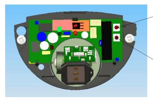
Pressing the two push buttons, located on the circuit board, simultaneously for three seconds, will restore all default settings.
1 5 2 6 3 7 4 8 5 (Default) 10 6 14 7 16 0 0.5
8 18 9 20
Setting Time (Seconds)


3 times.
Setting 1-3 Setting 4-6 Setting 7-9

Troubleshooting
| SYMPTOMS | PROBABLE CAUSE | CORRECTIVE ACTION |
|---|---|---|
|
Red LED does not light up.
(No power to sensor) |
Power switch is off.
Loose wire connection. |
Turn power switch to "ON" position.
Inspect wiring for loose connections. |
|
Door Stops several times in
the same cycle without sensing presence in the door way. |
Sensitivity is set too high |
Change sensitivity setting using
optional remote. |
|
Door not closing when cover
installed. |
Eye is sensing the closer
cover. |
Adjust the sensing field away from
cover edge. (See "Sensing Field Adjustments" above. |

3000 Highway 74 East • Monroe, NC 28112 Tel: (877)- • Fax: (800)-338-0965 974-2255 www.nortondoorcontrols.com