Norton Rixson 7100SZ Series Door Closer, SafeZone, External Sensor Installation Instructions_80-9371-0084-020
Open the original PDF document
View PDF

7100SZ Series SafeZone® External Sensor Installation and Instruction Manual
ASSA ABLOY
Patent Pending
Tools required:
- Allen wrench set (inch)
- Flat blade screwdriver (potentiometer & terminal size)
- Screwdriver (Phillips size 2)
- Tape rule
- Power drill
- Center punch
- Wire stripper
| Table of Contents: | |
|---|---|
| Mechanical Installation | 2 |
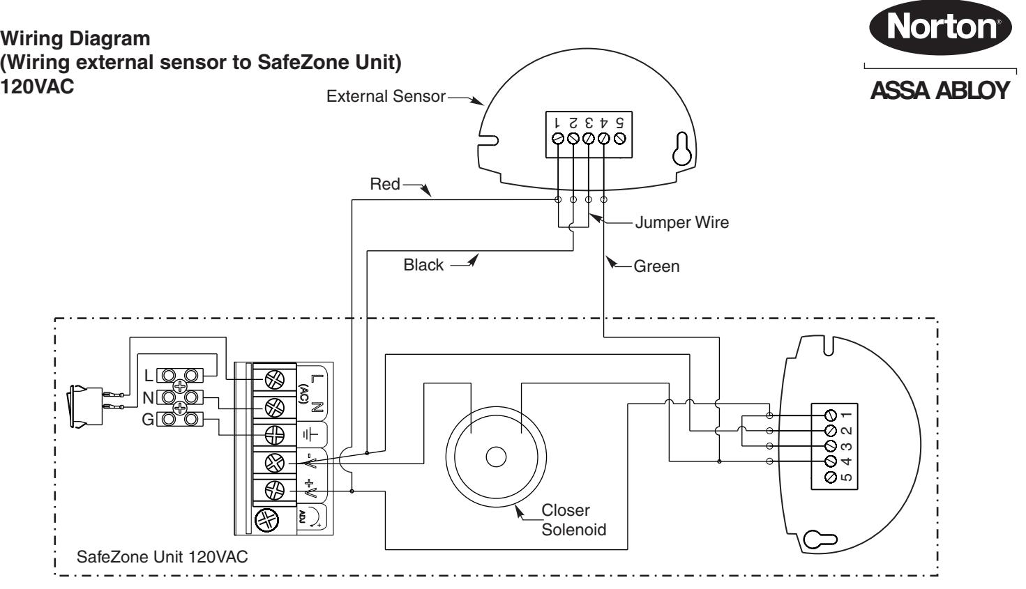
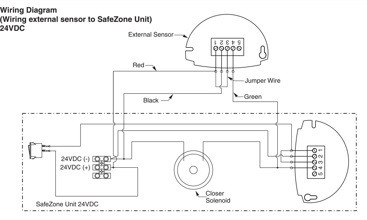
| Wiring Diagrams | 3 |
| Sensor Settings | 4 |
| Sensing Field Settings | 5 |
| Trouble Shooting | 5 |
| Specifications | 6 |
| Safety Precautions | 6 |
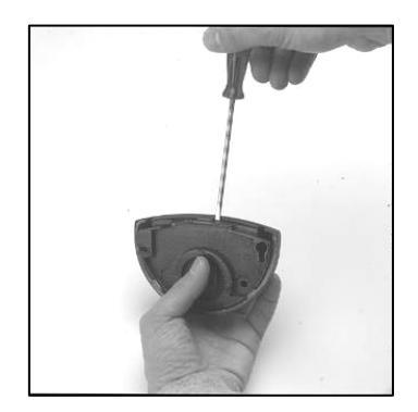
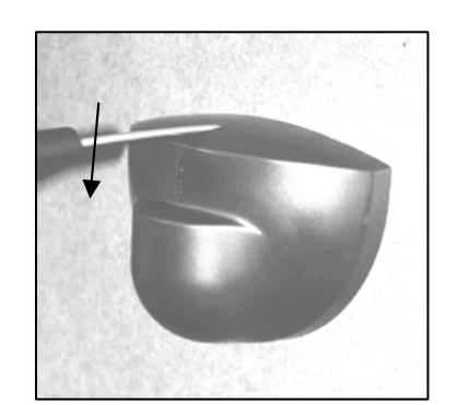
Opening the sensor

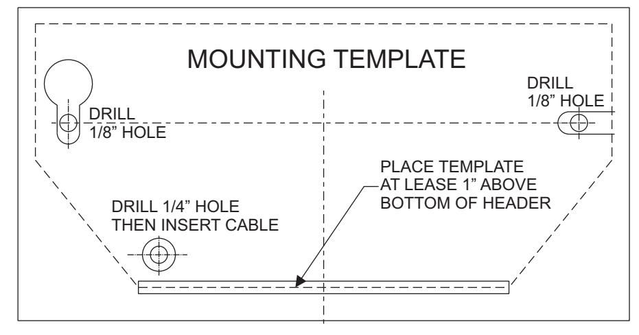
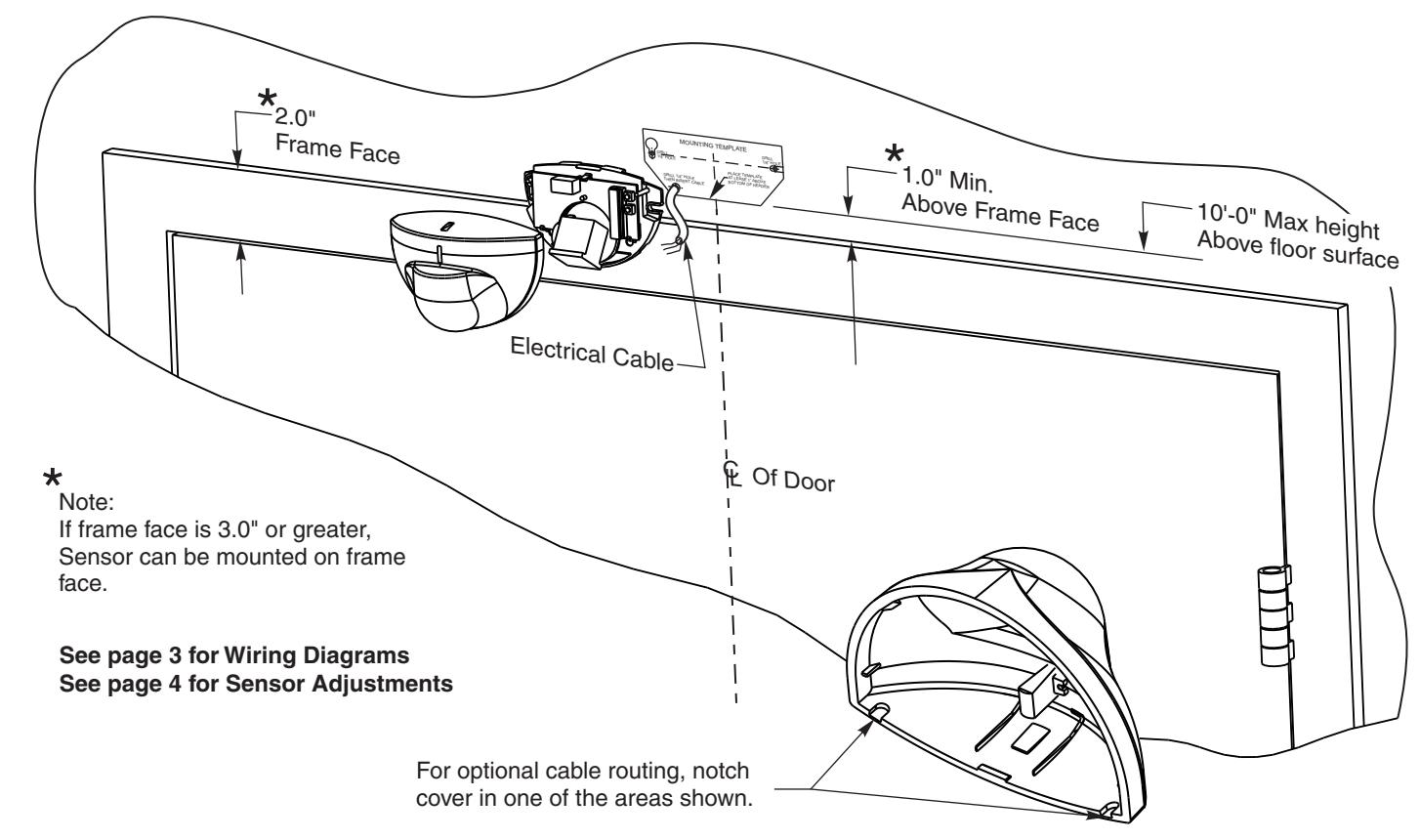
Mechanical Installation
- Apply adhesive backed template, supplied with sensor, to appropriate surface and aligned with centerline of door on side of opening opposite from SafeZone Mount.
- 2. Drill two 1/8" holes for mounting.
- 3. Drill one 1/4" hole for cable access.
- 4.Insert mounting screws into mount surface, but do not screw them fully in.
- 5. Route wiring through backplate.
- 6. Mount sensor backplate and tighten screws.
- 7. Complete wiring connections and sensor setup and testing.
- 8. Secure sensor cover to backplate.

Sensor Settings
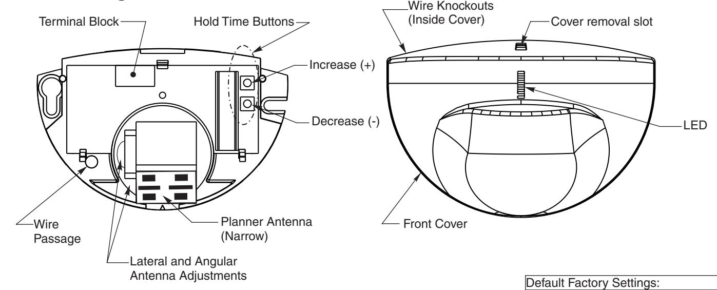
Hold Time
Hold open time is defined as the amount of time the door will remain open AFTER movement in opening is no longer detected.
Setting Hold Open Time:
Press and release the Increase (+) or decrease (-) buttons until desired setting is achieved.
Reset Hold Time to Default:
Holding both buttons depressed simultaneously for 3 seconds will set unit at default hold time of 10 seconds.
| Time (Seconds) |
|---|
| 0.5 |
| 5 |
| 6 |
| 7 |
| 8 |
| 10 |
| 14 |
| 16 |
| 18 |
| 20 |


Setting 1-3 Setting 4-6 Setting 7-9
Recommended Hold Time Settings
Sensitivity 3
Immunity 2
Door Control Mode 1
Hold Time 10 seconds
Detection Mode 1 (Bidirectional)
Sensitivity Setting
Sensitivity is factory set at setting #3. The sensitivity range is (0 - 9). This setting can be adjusted along with other advanced settings when using the optional remote.

4
Optional remote for advanced setting. List number 7100REM

Sensing Field Adjustments
The position of the sensing field is determined by the vertical and lateral angle of the antenna.
Vertical Angle Adjustments
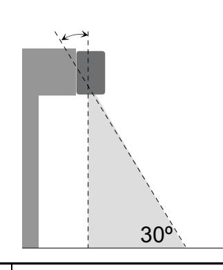
Sensing field as close to the door as possible: Antenna is set at the position of
Sensing field close to the door: Antenna is set at the position of
Sensing field far from the door: Antenna is set at the position of 45°
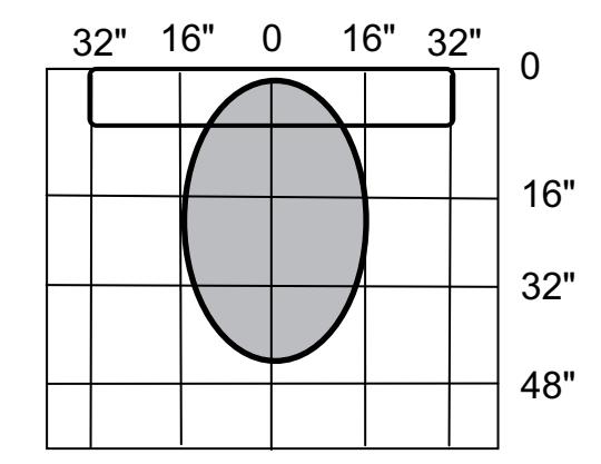
Nominal Detection Pattern with Sensor Set as follows:
| Mounting Height: | 7'-2" |
|---|---|
| Sensitivity: | 3 (factory default) |
| Immunity: | 2 (factory default) |
| Direction Mode: | 1 (Bi-Directional; factory default) |
| Door Control: | 1 (factory default) |
| Vertical Tilt: | 30° |
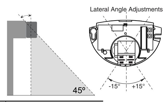
| Lateral Tilt: | 0° |
Altering the lateral tilt angle will shift the detection pattern left or right of center.

Always "walk" the opening during senor adjustment to confirm the detection pattern is adequate for the opening and application.
Adjusted hole open times as required for application. See page 4 for hold open time settings.
Troubleshooting
| SYMPTOMS | PROBABLE CAUSE | CORRECTIVE ACTION |
|---|---|---|
| Red LED does not light up. (No power to sensor) |
Power switch is off.
Loose wire connection. |
Turn power switch to "ON" position. Inspect wiring for loose connections. |
|
Door Stops several times in
the same cycle without sensing presence in the door way. |
Sensitivity is set too high | Change sensitivity setting using optional remote. |
| Door not closing when cover installed. | Eye is sensing the closer cover. | Adjust the sensing field away from cover edge. (See "Sensing Field Adjustments" above. |

Sensor Technical Specifications
| DESCRIPTION | SPECIFICATION |
|---|---|
| Frequency: | 24.125 GHz |
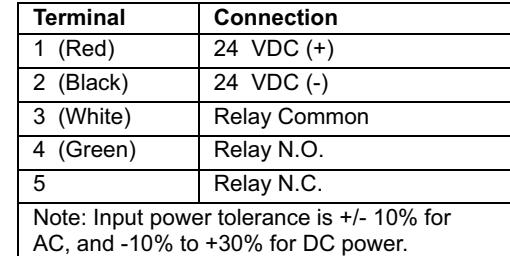
| Supply voltage: | 24 VDC: -10% / +30%: |
| Mounting height: | Normal: 7'; Maximum: 10'-0" |
| Tilt angle: | 0° to 90° vertical |
| -15° to +15° lateral | |
| Detection area: | |
| Wide | 13ft (W) x 6.5ft (D) |
| Narrow | 6.5ft (W) x 8.2ft (D) (supplied as optional) |
| Minimum detection speed: | 2 in/sec. (measured in axis) |
| Power consumption: | < 2 W |
| Standard output relay: | |
| Max contact voltage | 60 VDC / 125 VAC |
| Max contact current | 1 A (resistive) |
| Max switching power | 30W (DC) / 60VA (AC) |
| Hold time: | 0.5 sec. to 9 sec. (adjustable) |
| Temperature range: | -4°F to 131°F |
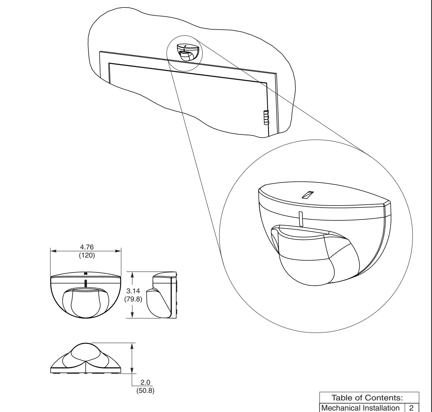
| Dimensions: | 4.75in (W) x 3.15in (H) x 2.0in (D) |
| Weight: | 0.5lbs |
| Material: | ABS |
Safety Precautions
- Shut off all power going to the header before attempting any wiring procedures.
- Maintain a clean & safe environment when working in public areas.
- Constantly be aware of pedestrian traffic around the door area.
- Always stop pedestrian traffic through the doorway when performing tests that may result in unexpected reactions by the door.
- Always check placement of all wiring and components before powering up to ensure that moving door parts will not catch any wires and cause damage to equipment.
- Ensure compliance with all applicable safety standards upon completion of installation.
ELECTROSTATIC DISCHARGE (ESD) PRECAUTIONS
Circuit board components are vulnerable to damage by electrostatic discharge (ESD). ESD can cause immediate or subtle damage to sensitive electronic parts. An electrostatic charge can build up on the human body and then discharge when you touch a board. A discharge can be produced when walking across a carpet and touching a board, for example. Before handling any board, make sure you dissipate your body's charge.
CAUTION: In the event a unit needs to be opened, observe the following precautions.
- Ground yourself by touching a conductive surface of the door or other element connected to common earth ground to discharge the static electricity present in your body.
- Avoid walking around while replacing items inside the case, especially if you are on carpet or during conditions of low temperature and low humidity.
- Handle the board by the edges only to avoid touching electronic components.
- Store a loose board in an anti-static bag.

3000 Highway 74 East • Monroe, NC 28112 Tel: (877)-974-2255 • Fax: (800)-338-0965 www.nortondoorcontrols.com