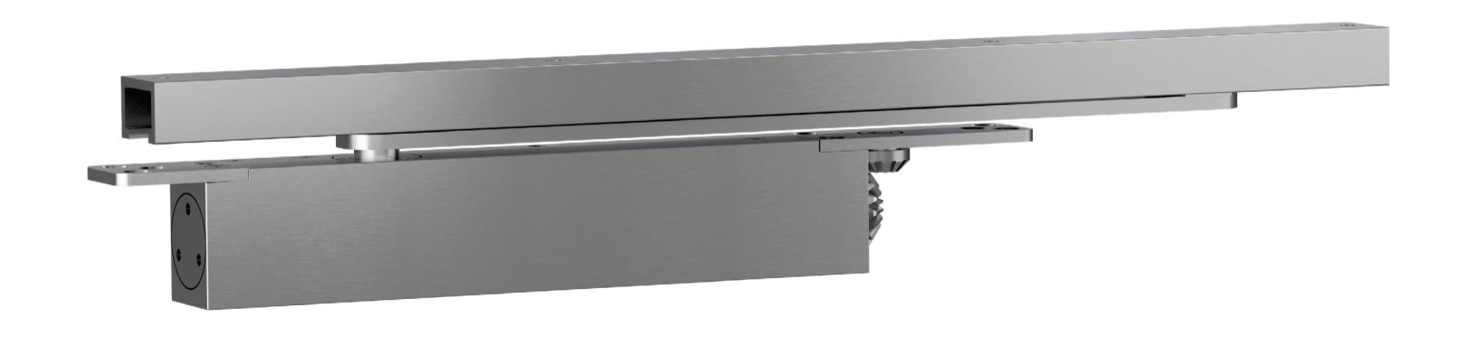
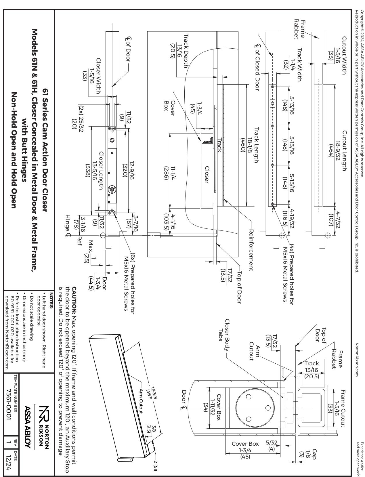
Norton Rixson 61 Series, Models 61N, 61H, Overhead Concealed Closer, Non-Hold Open & Hold Open, Pull and Push Sid…_80-9361-0001-020
Open the original PDF document
View PDFModel 61 Overhead Concealed Closer Cam Action Technology Non-Hold Open & Hold Open

Installation Instructions

This product can expose you to lead which is known to the state of California to cause cancer and birth defects or other reproductive harm. For more information go to: www.P65warnings.ca.gov.
An incorrectly installed or improperly adjusted door closer can cause property damage or personal injury. These instructions should be followed to avoid the possibility of misapplication or misadjustment.
READ AND FOLLOW ALL INSTRUCTIONS. SAVE THESE INSTRUCTIONS.
NOTES:
- y Non-handed. Can be used on right or left handed doors. Refer to page 2.
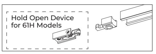
- y Size adjustable from 2 4. Refer to page 4
- y Frame/Door Types: Metal & Wood
- y Minimum Frame: 1" (25mm)
- y Minimum Door Thickness: 1-3/4" (44mm)
- y Maximum Opening Angle: 120°
CAUTION : If frame and wall conditions permit the door to be opened beyond the maximum 120°, an Auxiliary Stop is required. Do not exceed 120° of opening to prevent damage.
Non-Hold Open & Hold Open
Installation Instructions
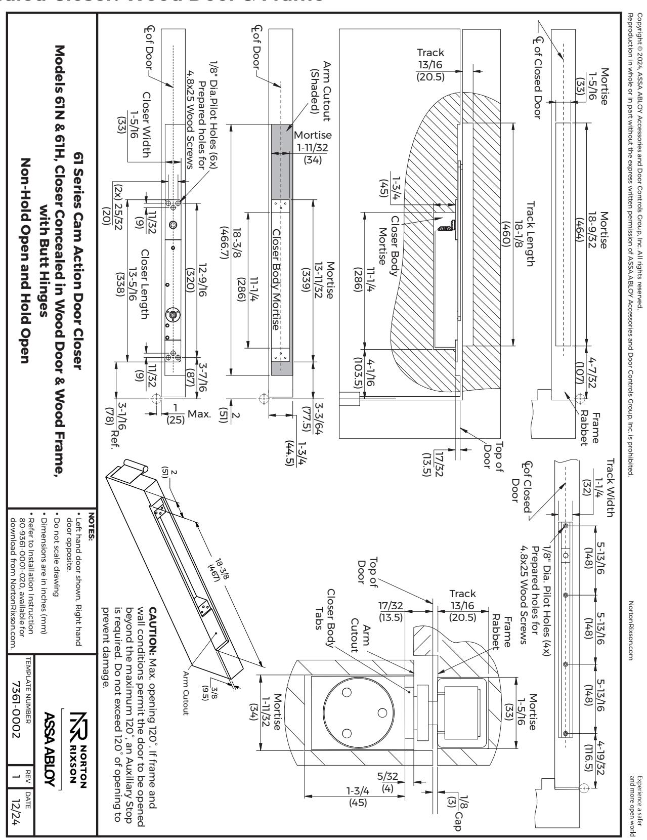
A. Prepare the door and frame for installation.
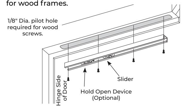
Refer to the template on page 5 for metal applications or page 6 for wood applications.
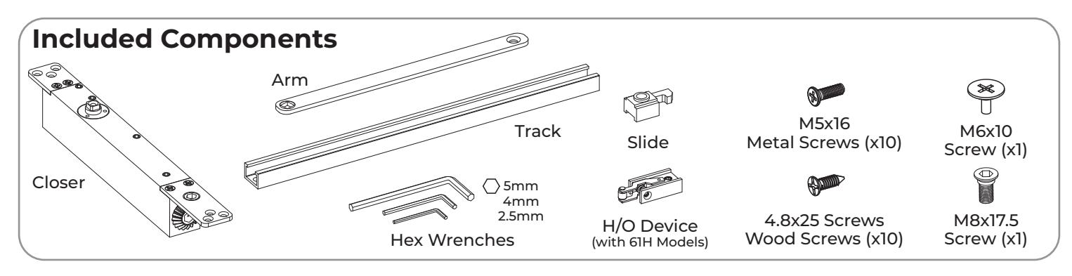
B. Assemble and install the track in the frame. C. Install the closer in the door.
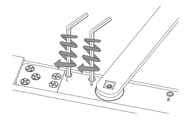
1. Assemble the track as shown.
2. Mount the track to the frame using four (4) M5x16 screws for metal frames or four (4) M4.8x25 screws
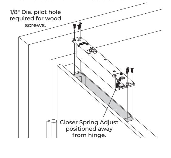
Mount the closer in the door using six (6) M5x16 screws for metal doors or six (6) M4.8x25 screws for wood doors.
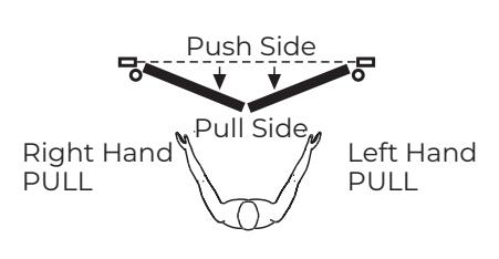
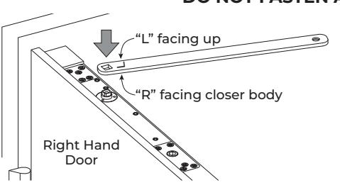
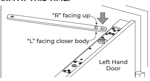
D. Determine door handing and attach arm.
Determine the door handing using the diagram below.
Place the square end of the arm on the closer spindle. DO NOT FASTEN ARM AT THIS TIME.
E. Close the sweep and latch valves fully.
Using the 2.5mm hex wrench, close the Latch and Sweep valves fully.
Non-Hold Open & Hold Open

Installation Instructions (cont.)
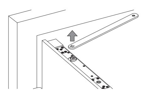
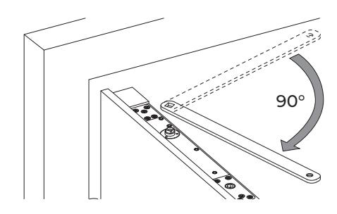
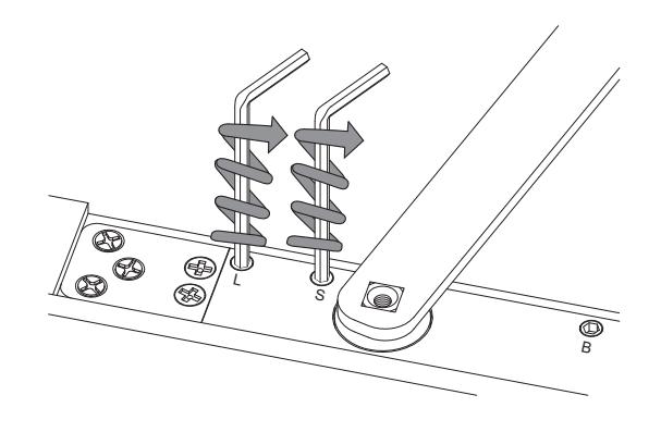
F. Preload the arm.
1. Rotate the arm approximately 40° as shown.
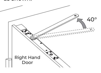
2. Remove the arm from the closer.
3. Rotate the arm 90°.
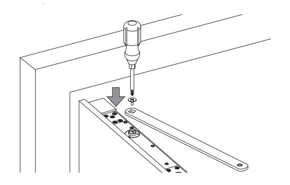
G. Fasten the arm to the closer.
With a Philips head screwdriver, use the M6x10 screw to attach the arm to the closer.
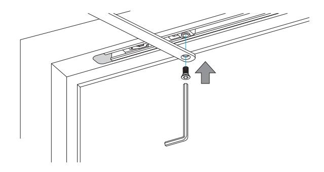
H. Fasten the arm to the track.
Rotate arm to position under the frame rabbet as shown.
Use the 5mm hex wrench to attach the arm to the track slider with the M8x17.5 screw.
I. Slowly open the sweep and latch valves.
CAUTION: Moving parts. Before performing this step, ensure all tools and people are clear of the doorway to prevent injury or damage.
Using the 2.5mm hex wrench, slowly open the Latch and Sweep valves, allowing the door to fully close.
Refer to "Closer Adjustments" on page 4 to adjust closer, if required.
3

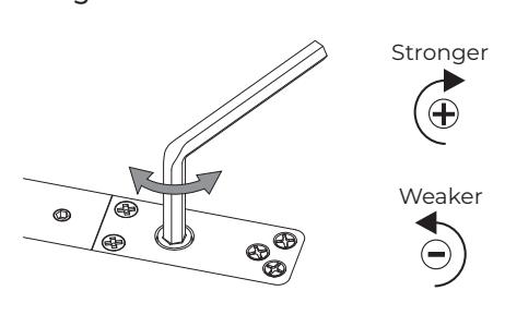
Closer Adjustments
Closer Spring Adjustment Adjusting the Closer
Use the 5mm hex wrench to adjust closing force.
With the 2.5mm hex wrench, adjust the closer latch, sweep, and backcheck settings.

*Do not close Backcheck valve fully. Do not use backcheck as a deadstop.
WARNING: Moving Parts
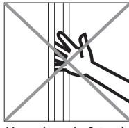
Keep hands & tools clear to avoid injury.
Do Not Use a Drill to Adjust the Closer
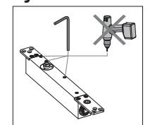
Use of a drill to adjust the closer will void the Warranty.
WARNING: Spring Under Pressure
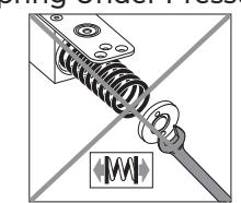
Removing the end cap may result in injury or damage.
Do Not Remove Valves from Closer
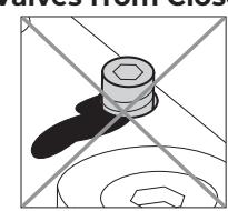
Removing the valves will result in a leak.
Technical Product Support: Monroe, NC 28112 USA Phone: 877.974.2255 ext: 2 Techsupport.NortonRixson@assaabloy.com NortonRixson.com
Non-Hold Open & Hold Open

Template: Models 61N/61H Concealed Closer: Metal Door & Frame

Non-Hold Open & Hold Open
Template: Models 61N/61H Concealed Closer: Wood Door & Frame