Norton Rixson 6000 Series Operator, 6011, 6021 with WiFi LAP Replacement Installation Instructions_80-9360-1034-020
Open the original PDF document
View PDF6011/6021 Series
LAP Replacement Installation Instructions


WARNING
This product can expose you to lead which is known to the state of California to cause cancer and birth defects or other reproductive harm. For more information go to www.P65warnings.ca.gov.
Pour la version francaise voir NortonRixson.com. READ AND FOLLOW ALL INSTRUCTIONS. SAVE THESE INSTRUCTIONS.
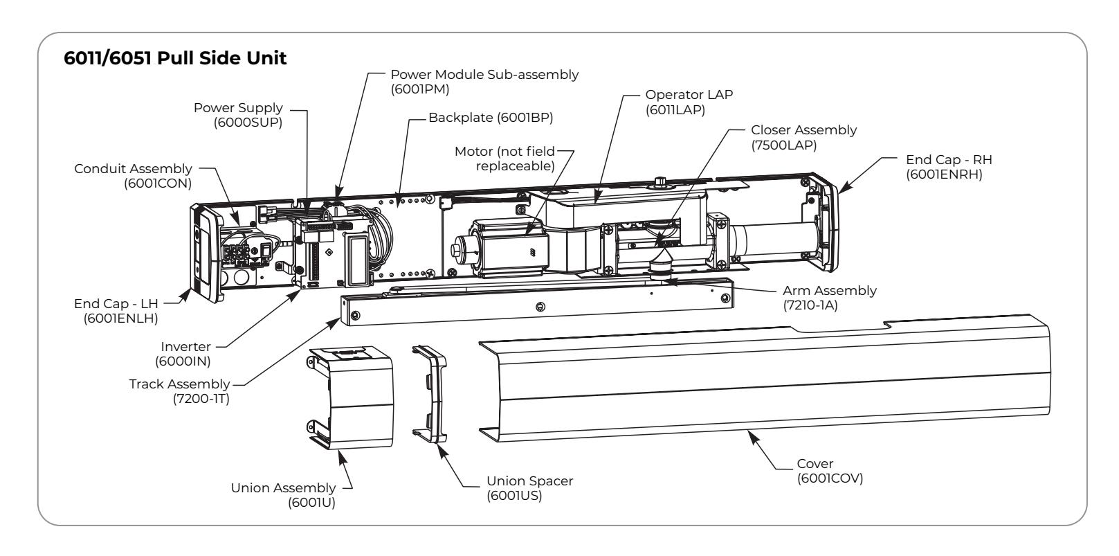

Prepare Unit for Replacement Operator LAP
A. Turn off control of door.
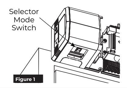
1. Open union assembly access door and flip selector mode switch to OFF position. (Figure 1)
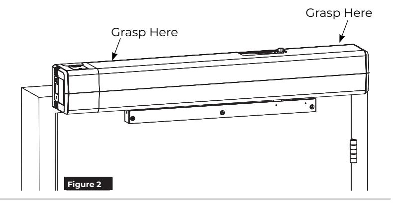
B. Remove Cover.
1. Grasping at locations shown, pull cover off of unit. (Figure 2)

NOTES:
- y Cover is not secured with screws.
- y Take care not to pull union assembly or end caps which are secured with screws.
C. 6011/6051 PULL Unit: Disconnect Arm from Pinion.


CAUTION: Arm will immediately start to move toward door frame.


6. Slide arm off pinion and release adjustable wrench.

C. 6021/6031/6061/6071 PUSH Unit: Disconnect Arm from Pinion.
- 1. Open door.
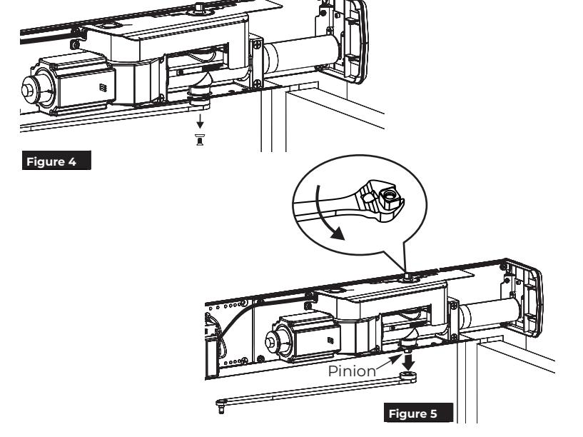
- 2. Using 7/16" wrench, remove pinion screw holding main arm on pinion. (Figure 6)
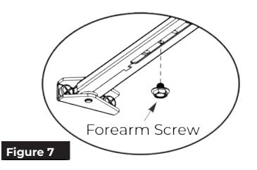
- 3. Using 7/16" wrench, loosen forearm screw in main arm rod and adjusting tube so that main arm can slide out of tube. (Figure 7)

CAUTION: Arm will immediately start to rotate.
4. When pinion and main arm rotate so main arm is perpendicular to door, slide main arm off of pinion.
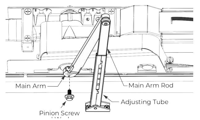
Figure 6 6021/6031 Arms Shown
D. Turn off power to unit.
1. Turn On/Off switch to OFF position on conduit assembly. (Figure 8)
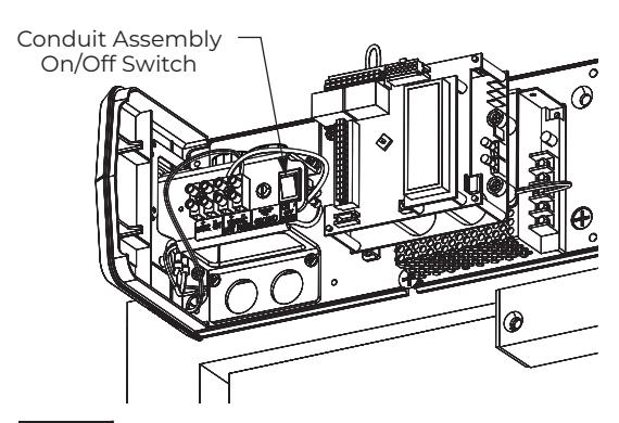
Union Assembly and Spacer not shown Figure 8

Replace Operator LAP
A. Disconnect Operator LAP from Power Module Sub-assembly.
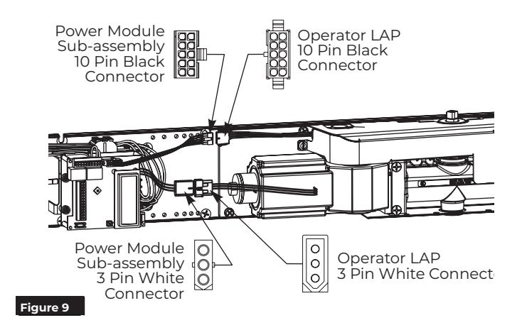
- 1. Detach 10-pin black connectors between operator LAP and power module subassembly. (Figure 9)
- 2. Detach 3-pin white connectors between operator LAP and power module subassembly. (Figure 9)
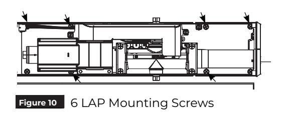
B. Remove Operator LAP.
- 1. Remove six (6) screws securing LAP to backplate. (Figure 10)
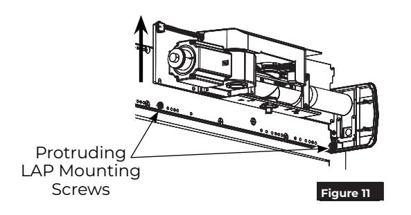
- 2. Loosen two (2) protruding screws and lift LAP off of unit. (Figure 11)
C. Install Replacement Operator LAP.
- 1. Orienting LAP so spring tube of closer is pointed toward hinge edge of frame, slide LAP over two (2) protruding screws and tighten. (Figure 11)
- 2. Using six (6) 1/4-20 x 1/2" Phillips head screws, secure LAP to backplate. (Figure 10)
NOTES:
- ‒ Holes in LAP align with threaded holes in backplate.
- ‒ Screws to be torqued to 80 in-lb minimum.
D. Connect Operator LAP and Power Module Sub-assembly.
- 1. Attach 10-pin black connectors between operator LAP and power module subassembly. (Figure 9)
- 2. Attach 3-pin white connectors between operator LAP and power module subassembly. (Figure 9)
NOTE: Connectors are keyed and only attach one way.

6011/6051 PULL Unit Reconnect Arm


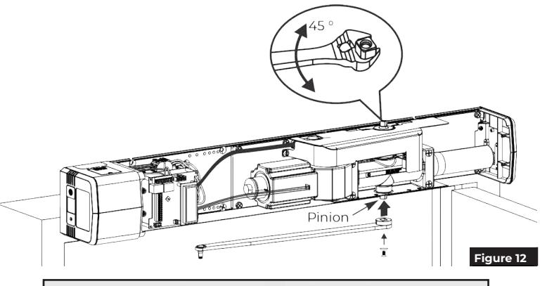
3. While holding pinion at 45 degrees, slide arm on bottom pinion parallel to frame as shown. (Figure 12)

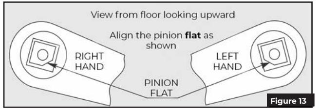
NOTE: Pinion flat should be aligned as shown. (Figure 13)
- 4. Secure arm to pinion with 1/4-20 x 1/2" screw and countersunk patch washer. (Figure 12)
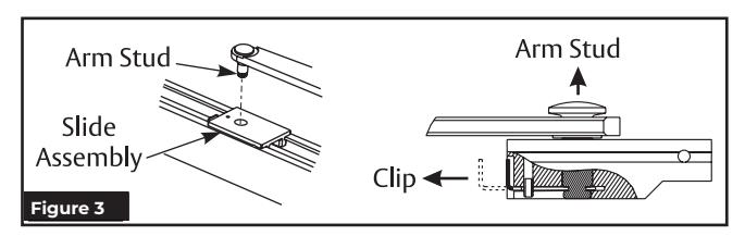
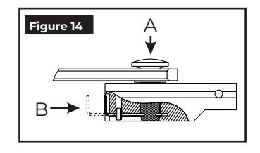
- 5. Insert stud on arm into slider in track by pressing clip on backside of slider onto stud. (Figure 14)
-
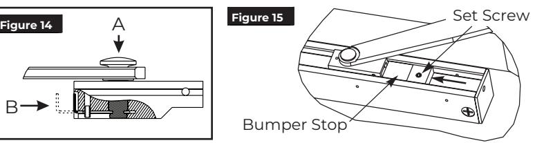
6. To adjust track stop:
- y Use allen wrench to loosen set screw in bumper stop.
- y Open door to full open position.
- y Slide bumper stop until it just touches end of slider. Arm Stud
- y Tighten set screw in bumper stop so bumper will stay in position. (Figure 15)
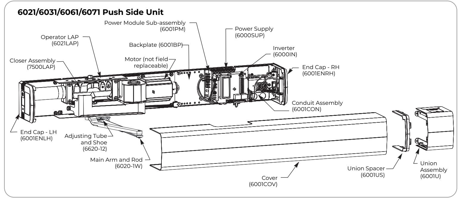
6021/6031/6061/6071 PUSH Unit
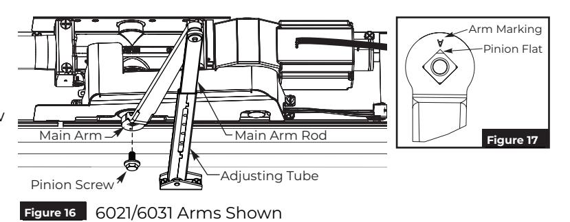
1. Place square of main arm onto closer pinion. (Figure 16)
NOTE: Pinion flat should be aligned as shown. (Figure 17)
- 2. Attach main arm to pinion with pinion screw and tighten with 7/16" wrench. (Figure 16)
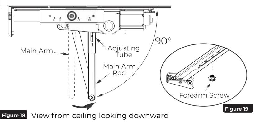
- 3. With door closed, rotate main arm away from hinge until adjusting tube is perpendicular (90 degrees) with door. (Figure 18)
- 4. While holding arm in position, secure rod to adjusting tube with forearm screw. (Figure 19)

Adjustments
A. Adjust mechanical closer features. NOTES:
- Make necessary mechanical adjustments so unit functions as a standard surface mounted door closer before adjusting spring force, applying power, adding accessories or making electrical/ programming adjustments.
- Valve location S/D is not adjustable.
- Chain protection plate cutouts allow access to valves. Use hex wrench to make adjustments. (Figure 20)

Do not remove valves from closer. Hydraulic oil will escape.
-
1. Closing Speed Controls (Figure 20)
- Valve "S" controls Sweep Range from full open to 10°.
- Valve "L" controls Latch Range from 10° to closed.
-
2. Opening Cycle (Figure 20)
- Valve "B" controls strength of cushioning in Backcheck Range.

NOTE: NEVER close Backcheck valve completely it is not to provide a positive stop.
Valve "P" adjusts angle that backcheck is felt in open cycle. Factory preset is typically acceptable.
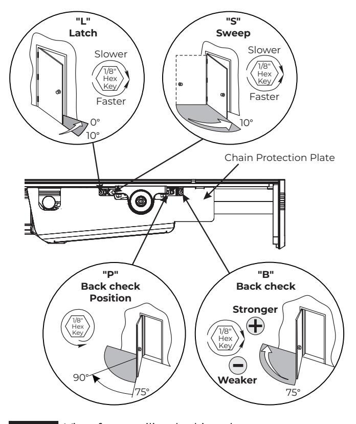
Figure 20 View from ceiling looking down
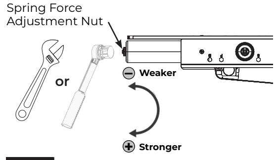
B. Adjust spring force. NOTES:
- The amount of effort to manually open or close a door is called force and is controlled by the operator's closer spring.
- Make necessary mechanical adjustments described in "A" above.
- A closer set to ADA required 5 lbs opening force may not be strong enough to close door due to latching hardware, air pressure, or frame issues.
Push Side Unit: Using an adjustable wrench or a ratchet with an 11/16" socket, turn the nut in end of closer body tube clockwise to increase or counterclockwise to decrease force until desired setting | Figure 21 | View from ceiling looking downward is reached. (Figure 21)
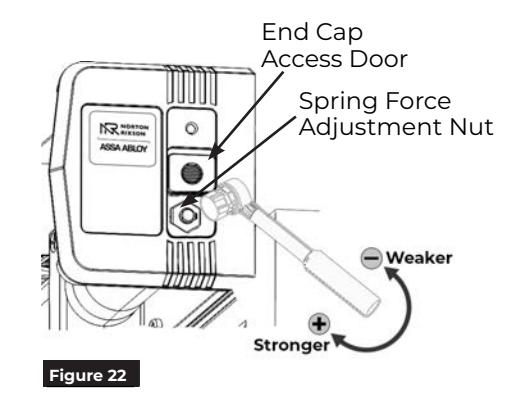
Pull Side Unit: To adjust the spring force, access the Spring Force Adjustment Nut through the End Cap Access Door.

- 2. Slide the End Cap Access door, exposing the spring adjustment nut.
- 3. Using a ratchet with an 11/16" socket, turn the nut in end of closer body tube clockwise to increase or counterclockwise to decrease force until the desired setting is reached. (Figure 22)
-
4. Once the desired force has been set:
- Remove the ratchet.
- Slide the end cap access door closed.
- Replace the end cap screw.


Power Operator
- 1. Turn on building power.
- 2. Turn On/Off switch to "ON" position on conduit assembly. (Figure 23)

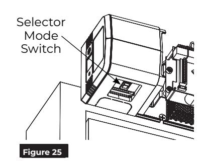
WARNING: Door may begin to move immediately when power is applied. An open union assembly door on a PULL unit has potential to pinch fingers if hand is not withdrawn quickly when switching on power. (Figure 25)
- y To scroll through menu items, push up or down on joystick. (Figure 23)
- y To change setting of a menu item, when cursor is on that item, push joystick right to increase or left to decrease value.
NOTE: Values will auto-save 3 seconds after adjustments.
-
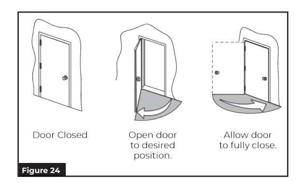
3. Set 'HOME' procedure for door.
- y With door closed and selector mode switch of union assembly in "OFF" position, use joystick to scroll down menu on LCD screen to "Home".
- y Push in on joystick to activate menu feature. Display changes to "Set Close Limit".
- y Push in on joystick again, while door is still closed, to set Home or closed position (Figure 24). Display changes to "Set Open Limit".
- y Open door to desired open position (Figure 24) and push in on joystick again. Display changes to "Closing to Home".
- y Allow door to fully close again (Figure 24). Display changes to "Home".
NOTE: Values will auto-save.
- 4. Make necessary adjustments to inverter and add required accessories.
- 5. Place selector mode switch of union assembly in 'ON' position for activation by push plate, RF button, or other activation devices. Place switch in 'H/O' for continuous hold open. (Figure 25) Secure union assembly door with #4 Phillips screw when finished.

WARNING: Door may begin to move immediately when selector mode switch is changed. An open union assembly door on a PULL unit has potential to pinch fingers if hand is not withdrawn quickly when adjusting switch. (Figure 25)
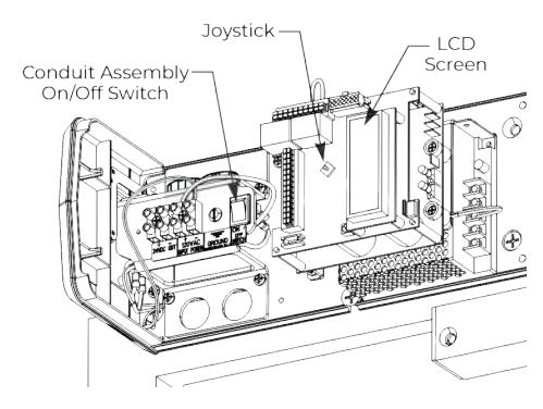
Figure 23 Union Assembly and Spacer not shown

Finalize Installation
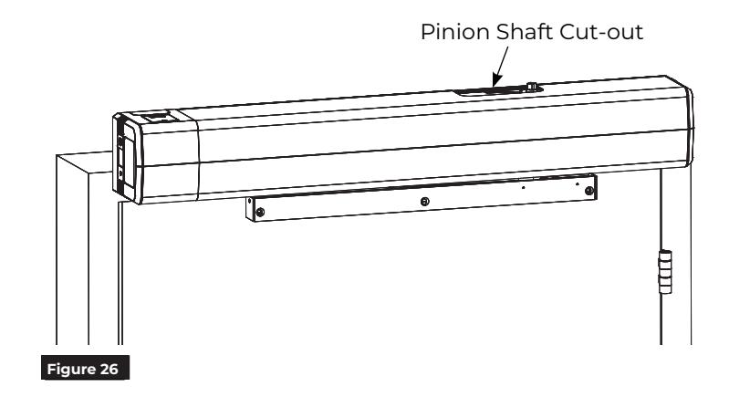
Attach Cover to finalize installation
- 1. Align cut-outs in cover to pinion shafts. (Figure 26)
-
2. Slide cover onto unit using end cap and union spacer as guides.
- NOTE: Verify all wiring and sheet metal guards are inside cover.
- 3. Snap cover securely to backplate. Pull on cover to verify it is secure.

WARNING: Make sure no wiring is loose or can be caught by cover when it is snapped into place.
You've now replaced the 6011 or 6021 Operator LAP .