Norton Rixson 5800 Series Low Energy Operator Wireless Interface Module (WIM) Installation and Operating Instruc…_700703
Open the original PDF document
View PDF

ASSA ABLOY
CAUTION
Changes or modifications not expressly approved by the party responsible for compliance could void the user's authority to operate this device.
To obtain the latest manual and template revisions or to view installation and programming videos go to www.NortonRixson.com. For technical support call 877-974-2255 ext. 2.

1 Purpose
Discussion
This manual provides system description, installation instructions, operating instructions, and troubleshooting recommendations for the Wireless Interface Module (referred to as the WIM). The WIM allows the door operator to interface with the wired or wireless push buttons, wireless remote, an electric lock, fire panel, access control, and an outside push button disable contact.
Applicability
This manual is applicable to the 5800 Series Wireless Interface Module.
2 Prerequisites
- 1. A 5800 Series door operator installed according to 5800 Series Low Energy Operator Installation and Operating Instructions p/n 700002 with optional Hardwire Kit p/n 1015 or 24VDC (500ma minimum) power supply by others.
- 2. 12 or 24V AC or DC to power the WIM.
- 3. 24VDC is REQUIRED if the 5800 door operator will be powered thorough the WIM with the supplied cable.
- 4. Protective barrier (caution/warning tape) has been set up to prevent unauthorized access to work area.
- 5. The door has been secured to prevent unexpected opening or closing during installation.
3 Precautions
- 1. This product is intended for interior use only.
- 2. An operating door creates pinch hazards. Be careful making operating adjustments while the door is moving.
- 3. The transformer wiring must not be concealed behind walls or routed through doorways, window openings, walls, ceilings, or floors. Also, this wiring must be secured to prevent it from becoming entrapped in the moving parts of the operator or door.


4 System Description
General
The WIM allows the door operator to interface with:
- Wireless (RF) push buttons or
- Wired push buttons
- Wireless (RF) hand held transmitter
- Electric Lock
- Access Control
- Fire Panel
- Switch to disable outside push button
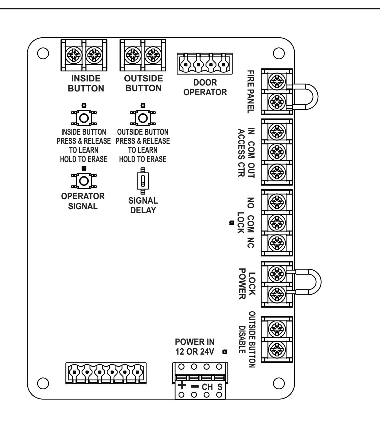
5 Inputs & Outpus
- 1. Push Buttons: A wired and wireless input is provided for an INSIDE and an OUTSIDE push button. An optional handheld transmitter (p/n ADA1031) may be programmed to either the INSIDE or OUTSIDE activation connection.
- 2. Operator Connection: A cable assembly (p/n ADA1015C) is provided to plug in the door operator into the WIM module.
- 3. Access Control: Contacts are provided to interface the WIM with access control.
- 4. Lock Interface: Contacts are provided to control an electrical lock.
- 5. Lock Power: Contacts are provided to power an electric lock.
- 6. Outside Push Button Disable: A contact is provided to disable any input from an outside push button.
- 7. Power Input: A power input connector is provided to power the WIM by a 12 or 24V AC/DC* power supply or using the optional hardwire kit (p/n ADA1015P).
-
8.
Signal Delay:
A switch is provided to enable a 1 second delay before sending an activate signal to the door operator.
- *If the Door Operator will be powered using the supplied cable assembly (p/n ADA1015C) the WIM must be powered by a 24VDC 750mA minimum power supply.

6 Mount and Apply Power to the WIM
1. Mount the WIM enclosure in a remote location as desired.
NOTE:
The WIM may be powered by 12 or 24 Volts AC or DC current. If the door operator will be powered directly from the WIM, a 24VDC 750ma (minimum) power supply is required.
-
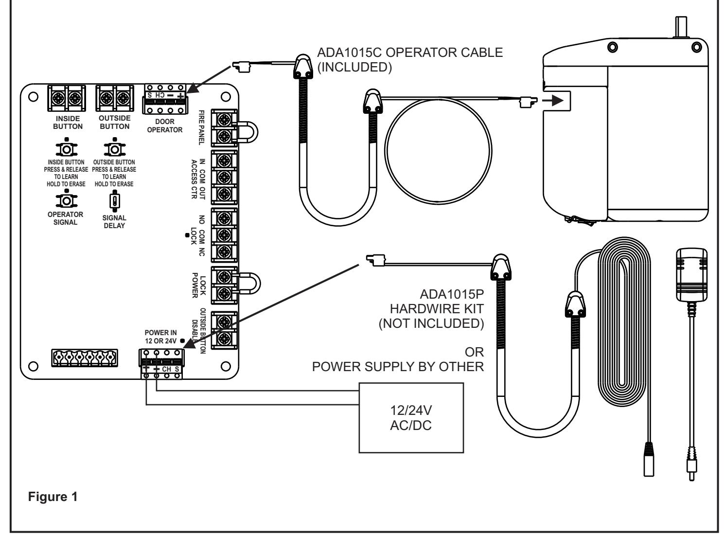
2.
Provide power to the WIM
. (Refer to Figure 1)
- a. If the Optional hardwire kit (p/n ADA1015P) is used to power the WIM and door operator, plug the provided GREEN connector into the power port as shown.
- b. If Power supply is by others, connect the power supply using the provided GREEN connector. If a DC power supply is used connect the ground to the terminal marked "-" and the positive to the terminal marked "+".
- c. If the operator will be powered through the WIM,use the supplied Operator Wire Harness (p/n ADA1015C) to power the Operator. When power is properly applied to the operator, the LED on the bottom of the battery pack will light steady GREEN.
- d. When the WIM is properly wired with power applied LED D8 near the power connector will light GREEN.

7 Erase All RF Codes from the Door Operator
NOTE:
The door operator is shipped with wireless RF push buttons that are pre-programmed to the operator. The RF codes MUST be erased from the door operator for proper operation.
1. Refer to Figure 2 and Remove the bottom cover from the door operator to access the Setup board.
- 2. Refer to Figure 3. PRESS and HOLD the LEARN button and PRESS and RELEASE the RESET button on the setup board.
- 3. LEDs DS8 through DS11 shall flash GREEN.
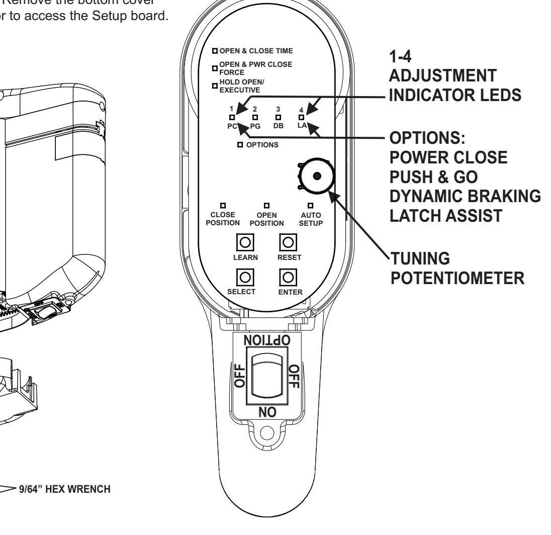
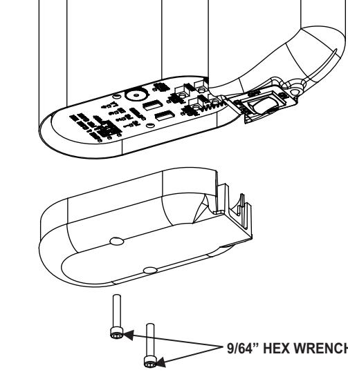
Figure 2 Figure 3
8 Learn WIM Module to Door Operator
- 1. Refer to Figure 3 and PRESS and HOLD the LEARN button until on the Operator Control board until LEDs DS8-DS11 Flash Green.
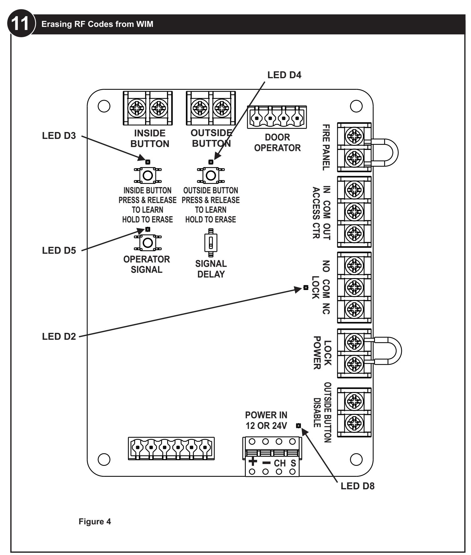
- 2. Refer to Figure 4 and PRESS and RELEASE the "OPERATOR SIGNAL" button on the WIM.
- 3. On the Setup board, LEDs DS8 through DS11 shall rapidly flash GREEN 3 times.

9 Connect Push Buttons and/or Handheld Remote to WIM
NOTE:
The push buttons may be connected by wire or wireless connection to either the INSIDE activation or OUTSIDE activation. If an optional Handheld Transmitter (not included) was purchased it may be connected to either the INSIDE or OUTSIDE activation inputs.
An INSIDE activation is considered to be an input from the SECURE side of the door. An INSIDE activation will switch the LOCK contact, the ACCESS CTR output contact, and send an activation signal to the door operator.
An OUTSIDE activation is considered to be an input from the NON-SECURE side of the door. An OUTSIDE activation will switch the LOCK contact, the ACCESS CTR output contact, and send an activation signal to the door operator ONLY if the ACCESS CTR INPUT contact is CLOSED.
- 1. Refer to Figure 4. If the push buttons will be hard wired, connect the INSIDE and OUTSIDE push buttons to the WIM module contacts labeled INSIDE BUTTON and OUTSIDE BUTTON.
-
2. If the INSIDE push button will be connected using RF activation, it must be learned to the WIM.
- a. Refer to Figure 4 and PRESS and RELEASE the "INSIDE BUTTON" button.
- b. The Audible will beep and the LED above the button will flash RED if no RF signals have been learned or GREEN if an RF button is already stored in memory. If the audible sounds a steady beep and the RED LED lights flashes
- 4 times rapidly the RF memory is full and must be reset in order to learn a new RF activation signal.
- c. Press and release the INSIDE push button (or optional handheld transmitter or optional push button) 2 times.
- d. The LED will flash and the audible will beep 4 times if the RF signal was successfully learned.
- e. If the push button is not learned the audible will beep for two seconds and exit learn mode.
-
3. If the OUTSIDE push button will be connected using RF activation, it must be learned to the WIM.
- a. Refer to Figure 4 and PRESS and RELEASE the "OUTSIDE BUTTON" push button.
- b. The Audible will beep and the LED above the button will flash RED if no RF signals have been learned or GREEN if an RF button is already stored in memory. If the audible sounds a steady beep and the RED LED lights flashes 4 times rapidly the RF memory is full and must be reset in order to learn a new RF activation signal.
- c. Press and release the OUTSIDE push button (or optional handheld transmitter or optional push button) 2 times.
- d. LED D4 will flash and the audible will beep 4 times if the RF signal was successfully learned.
- e. If the push button is not learned the audible will beep for two seconds and exit learn mode.
10 Erasing RF Codes from WIM
- 1. Refer to Figure 4 and PRESS and HOLD the INSIDE BUTTON push button on the WIM for 5 seconds
- 2. LED D3 will flash RED 4 times and the audible will beep for 4 seconds
- 3. Refer to Figure 4 and PRESS and HOLD the OUTSIDE BUTTON push button for 5 seconds
- 4. LED D4 will flash RED 4 times and the audible will beep for 4 seconds
- 5. All learned RF codes are now erased.


12
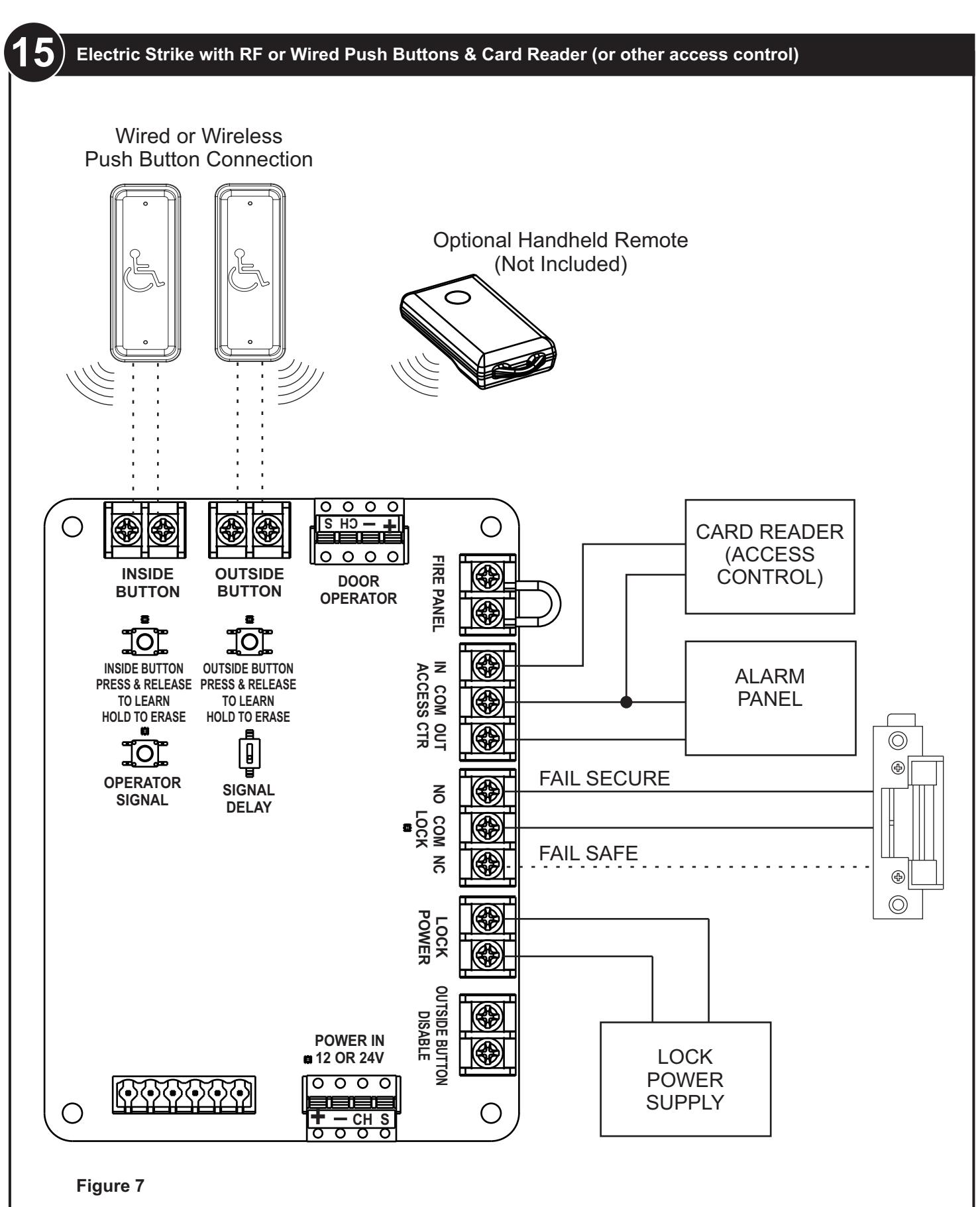
Connect an Electric Lock to the WIM
NOTE:
The electric lock contact will switch state when the INSIDE push button is activated OR the Access Control input contact is CLOSED.
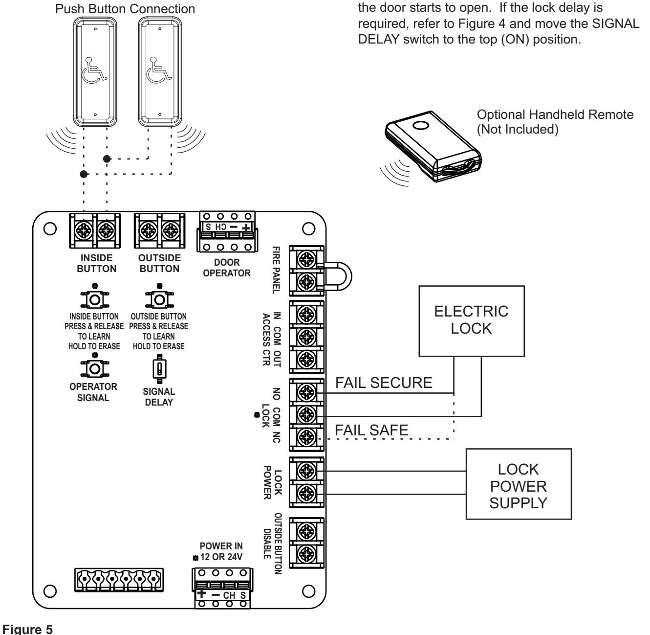
1. An electric lock may be connected to the WIM as shown in Figure 5.
Wired or Wireless
- A normally open or normally closed contact are provided for fail safe or fail secure lock installation. Connect the lock and power supply to the WIM as shown in Figure 5.
- 3. An optional signal delay is provided to add a one second time delay between receiving an activate signal and sending an activate signal to the door operator. This allows additional time for the lock to unlock before the door starts to unlock before the door starts to open. If the lock delay is required, refer to Figure 4 and move the SIGNAL DELAY switch to the top (ON) position.

13
Connect the WIM to Access Control, Alarm Panel, or Fire Panel
NOTE:
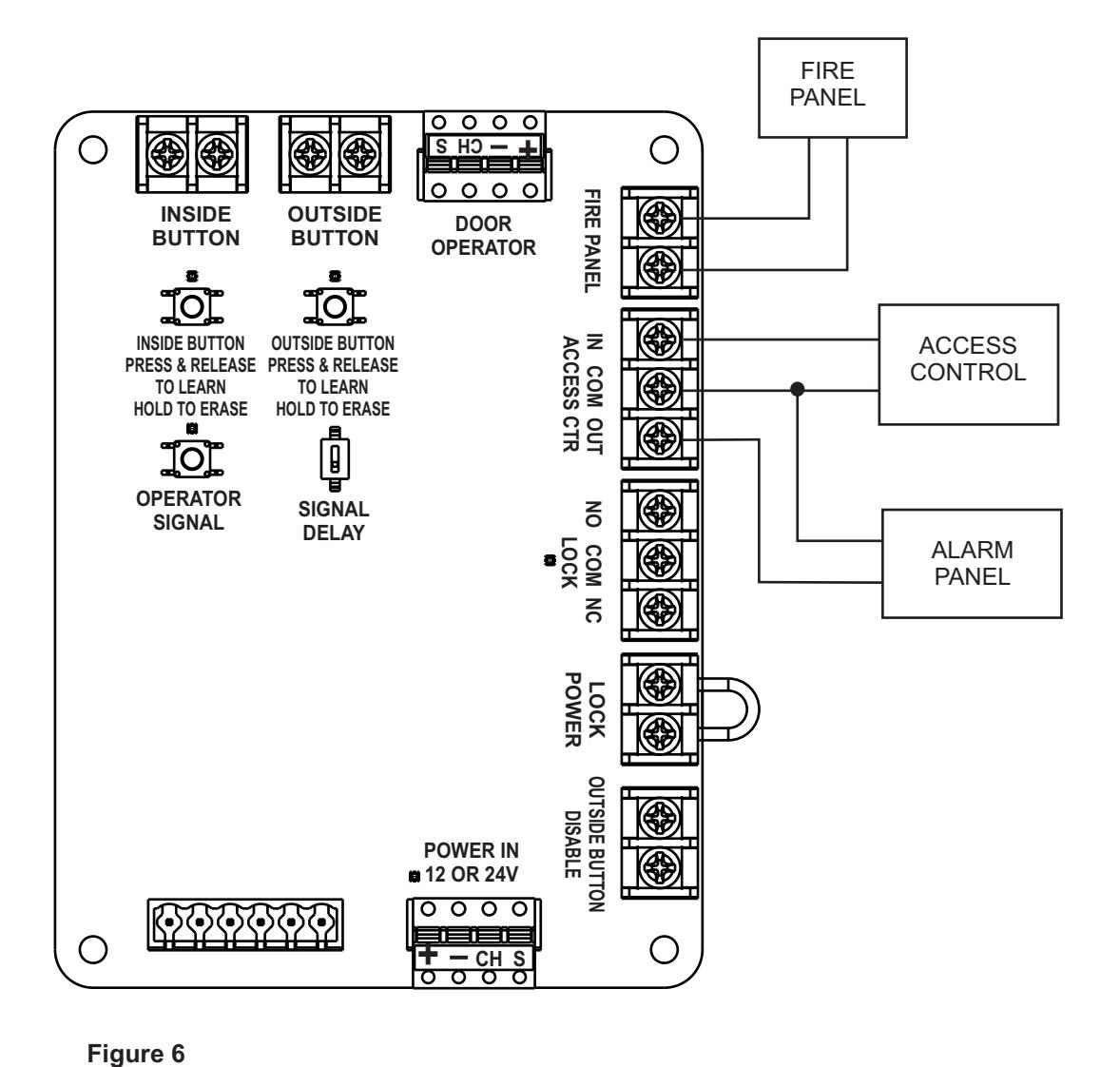
Closing the ACCESS CTRL IN contact will switch the state of the LOCK contact and enable the OUTSIDE push button.
The ACCESS CTRL OUT contact will close when the WIM module has received an authorized signal to switch the LOCK contact.
Opening the FIRE PANEL contact will prevent the door operator from accepting an activate signal or will close the door operator if it is in the open position.
1. Refer to Figure 6 and connect the optional Access Control Input contact, Alarm Panel Output contact, or Fire Panel Input contact.


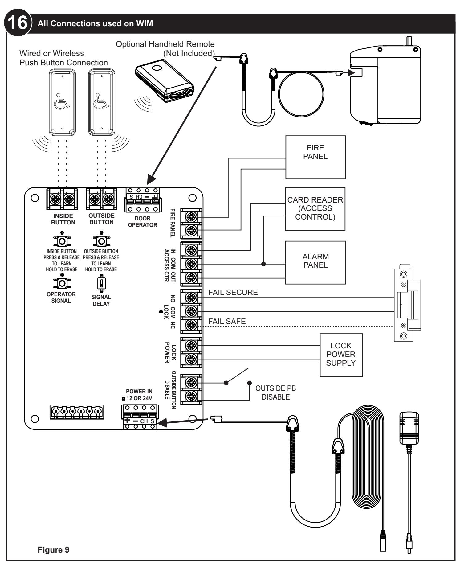
Connect the Outside Push Button Disable
NOTE:
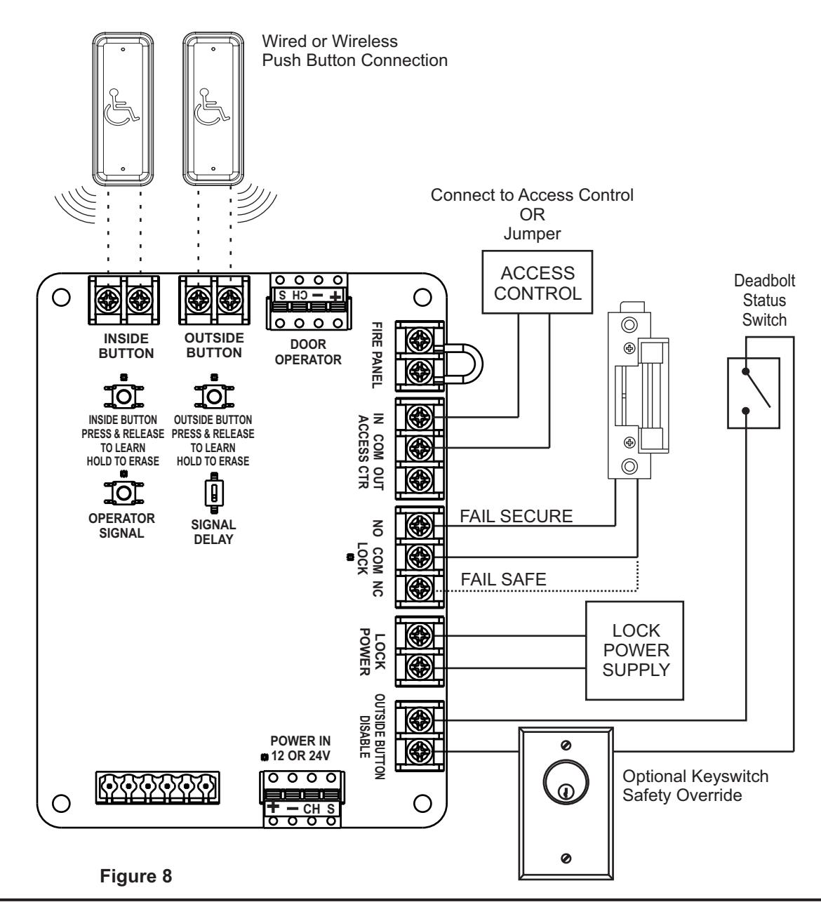
Closing the OUTSIDE BUTTON DISABLE contact will prevent the WIM from accepting an activation signal from the OUTSIDE push button. When the OUTSIDE BUTTON DISABLE contact is closed the WIM will only switch the lock state and activate the operator when an INSIDE push button signal is received.
An optional Keyswitch or Access Control device may be hard wired in series with the Outside Disable Button to enable the Lock and Outside Push Button
- Refer to Figure 6 and Connect the OUTSIDE PUSH BUTTON DISABLE contact to the deadbolt monitoring switch.
- 2. Connect a Card Reader Access control OR Place a Jumper across the ACCESS CTRL IN and COM.
NOTE:
Placing a jumper across the ACCESS CTRL IN and COM will maintain the lock in the UNLOCKED condition unless the OUTSIDE BUTTON DISABLE contact is CLOSED.


17 Troubleshooting Recommendations
| No | Symptom | Recommended Remedy |
| 1 |
LED D8 does not light
Green when Operator cable is plugged into WIM and operator. |
If using the ADA1015P hardwire kit verify the black wire with
· white stripe is plugged into the "-" terminal and the black wire is plugged into the "+" terminal. |
|
·
If using Power supply by other, verify the wires from the power supply are the correct polarity and plugged intot the "-" and "+" terminals. |
||
|
Verify the wires are fully seated and making a good connection.
· |
||
|
·
Using a multimeter, insert the probes into the holes below the "-" and "+" terminals and verify 12 or 24 Volts AC or DC voltage. |
||
| 2 |
The LED on the battery
pack does not light steady GREEN when powered by the provided operator cable ADA1015C. |
Verify that 24VDC is being supplied to the POWER IN
· connection on the WIM and LED D8 near the connector is lighted steady GREEN. |
|
·
On the Operator Cable ADA1015C, Verify the black wire with white stripe is plugged into the "-" terminal and the black wire is plugged into the "+" terminal on both ends of the cable. |
||
|
Verify the wires are fully seated into both green connectors on
· both ends of the cable. |
||
|
Using a multimeter, insert the probes into the holes below the
· "-" and "+" terminals and verify 24 VDC on the Operator end of the Operator Cable ADA1015C. |
||
| 3 |
RF Push Buttons or
Optional Handheld Remote ADA1031 (Not Included) will not Sync to WIM |
·
Verify the voltage of the CR2032 battery is above 3.0V and replace battery if necessary. |
|
·
Unwrap the antenna wire on the WIM and extend the wire through a hole in the enclosure. |
||
|
·
If programming an INSIDE BUTTON Press and hold the INSIDE BUTTON switch on the WIM for 5 seconds to erase all existing learned transmitters. Re-learn using procedure above. |
||
|
·
If programming an OUTSIDE BUTTON Press and hold the OUTSIDE BUTTON switch on the WIM for 5 seconds to erase all existing learned transmitters. Re-learn using procedure above. |
||
| 4 |
Operator will not sync to
WIM |
Verify the jumper on the FIRE PANEL contact is in place.
· |
|
·
Verify the OUTSIDE BUTTON DISABLE contact is not closed. |
||
|
Erase all existing RF codes from Operator (on the Operator
· setup board, PRESS and HOLD LEARN, PRESS and RELEASE RESET). |

17 Troubleshooting Recommendations - con't
| No | Symptom | Recommended Remedy |
| 5 |
Lock does not unlock
when an INSIDE activation is sent. |
·
If RF buttons are used and LED D3 is NOT flashing perform troubleshooting steps in section "RF transmitters will not Sync to WIM" |
|
·
If hardwired buttons are used and D3 is NOT flashing: |
||
|
o
verify wires are connected to the Common (C) and Normall Open (NO) switch contacts. |
||
|
o
Use a multimeter to verify a contact closure on INSIDE BUTTON. |
||
|
·
If LED D3 is flashing |
||
|
Verify the jumper on the FIRE PANEL is in place.
o |
||
|
·
Measure the voltage across the LOCK POWER input and verify the correct voltage for the lock. |
||
| 6 |
Lock does not unlock
when an OUTSIDE activation is sent. |
If RF buttons are used and LED D4 is NOT flashing perform
· troubleshooting steps in section "RF transmitters will not Sync to WIM" |
|
·
If hardwired buttons are used and D4 is NOT flashing: |
||
|
o
verify wires are connected to the Common (C) and Normall Open (NO) switch contacts. |
||
|
Use a multimeter to verify a contact closure on
o INSIDE BUTTON. |
||
|
·
If LED D4 is flashing |
||
|
o
Verify the ACCESS CTR IN contact is closed while activation is being sent. The WIM will not accept an OUTSIDE activation unless a valid access control input is received. |
||
|
o
Verify OUTSIDE BUTTON DISABLE contact is not closed. |
||
|
o
Verify the jumper on the FIRE PANEL is in place. |
||
|
o
Measure the voltage across the LOCK POWER input and verify matching voltage with lock. |
||
| 7 |
The OUTSIDE BUTTON
disable does not prevent the lock from unlocking |
o
Verify the button is programmed/connected to the OUTSIDE BUTTON contact. |

17 Troubleshooting Recommendations - con't
| No | Symptom | Recommended Remedy |
|---|---|---|
| 8 |
The operator does
· not activate when pushing the INSIDE push button · · |
If RF buttons are used and LED D3 is NOT flashing perform
troubleshooting steps in section "RF transmitters will not Sync to WIM" |
| If hardwired buttons are used and D3 is NOT flashing: | ||
|
verify wires are connected to the Common (C) and
o Normally Open (NO) switch contacts. |
||
|
o
Use a multimeter to verify a contact closure on INSIDE BUTTON. |
||
| IF LED D3 IS flashing & LED D5 IS flashing | ||
|
o
Verify LEDs on setup board are lighting. If LEDs on setup board do not light, Erase all learned codes from the operator and re-sync the WIM to the operator. |
||
|
o
Verify the operator has been programmed using the procedure in the Installation and Operating Instructions. |
||
|
·
IF LED D3 IS flashing and LED D5 is NOT flashing |
||
|
o
Verify the jumper on the FIRE PANEL is in place. |
||
|
·
Turn the Signal Delay switch to the "ON" position. |
||
| 9 |
The operator does
not activate when pushing the |
·
If RF buttons are used and LED D4 is NOT flashing perform troubleshooting steps in section "RF transmitters will not Sync to WIM" |
|
OUTSIDE push
button |
If hardwired buttons are used and D4 is NOT flashing:
· |
|
|
verify wires are connected to the Common (C) and
o Normally Open (NO) switch contacts. |
||
|
o
Use a multimeter to verify a contact closure on INSIDE BUTTON. |
||
|
·
IF LED D4 IS flashing & LED D5 IS flashing |
||
|
o
Verify LEDs on setup board are lighting. If LEDs on setup board do not light, Erase all learned codes from the operator and re-sync the WIM to the operator. |
||
|
o
Verify the operator has been programmed using the procedure in the Installation and Operating Instructions. |
||
|
·
IF LED D3 IS flashing and LED D5 is NOT flashing |
||
|
o
Verify the ACCESS CTR IN contact is closed while activation is being sent. The WIM will not accept an OUTSIDE activation unless a valid access control input is received. |
||
|
Verify OUTSIDE BUTTON DISABLE contact is not closed.
o |
||
|
o
Verify the jumper on the FIRE PANEL is in place. |
||
|
o
Turn the Signal Delay switch to the "ON" position. |

NOTES
Changes or modifications not expressly approved by the party responsible for compliance could void the user's authority to operate this device. This device complies with part 15 of the FCC Rules. Operation is subject to the condition that this device does not cause harmful interference.
This equipment has been tested and found to comply with the limits for a Class A digital device, pursuant to part 15 of the FCC Rules. These limits are designed to provide reasonable protection against harmful interference when the equipment is operated in a commercial environment. This equipment generates, uses, and can radiate radio frequency energy and, if not installed and used in accordance with the instruction manual, may cause harmful interference to radio communications.
This device complies with Industry Canada's licence-exempt RSSs. Operation is subject to the following two conditions:
- (1) This device may not cause interference; and
- (2) This device must accept any interference, including interference that may cause undesired operation of the device.
Le présent appareil est conforme aux CNR d'Industrie Canada applicables aux appareils radio exempts de licence. L'exploitation est autorisée aux deux conditions suivantes :
- 1) l'appareil ne doit pas produire de brouillage;
- 2) l'appareil doit accepter tout brouillage radioélectrique subi, même si le brouillage est susceptible d'en compromettre le fonctionnement.
Technical Product Support: Monroe, NC 28112 USA Phone: 877.974.2255 ext: 2